

What Does kVA Mean on a Transformer Rating?
kVA (kilovolt-ampere) represents the apparent power capacity of a transformer, indicating the maximum voltage and current the unit can handle simultaneously without overheating. Unlike kW (kilowatts) which measures only real power, kVA accounts for both active power (kW) and reactive power (kVAR), making it independent of the load power factor. This rating ensures the transformer can supply any type of load—resistive, inductive, or capacitive—without manufacturer knowledge of the specific application.
သော့ထုတ်ယူမှုများ
- kVA measures apparent power (voltage × current), while kW measures only real power that performs actual work
- Transformers are rated in kVA, not kW, because manufacturers cannot predict the power factor of future loads
- Copper losses depend on current (I²R), iron losses depend on voltage—both determine thermal limits expressed in VA
- Single-phase kVA calculation: kVA = (Voltage × Current) / 1000
- Three-phase kVA calculation: kVA = (Voltage × Current × 1.732) / 1000
- အမြင့်ဆုံးထိရောက်မှု typically occurs at 70-80% of rated kVA load
- Always size transformers with 20-25% safety margin above calculated load to prevent overload and allow for future expansion
The Power Triangle: Understanding kW, kVAR, and kVA
To comprehend why transformers use kVA ratings, one must first understand the relationship between different types of power in AC electrical systems. Electrical power in alternating current circuits consists of three components forming what engineers call the “power triangle.”
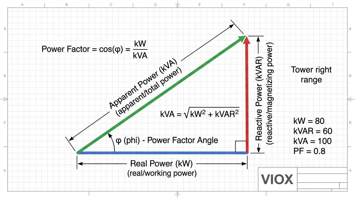
Real Power (kW) represents the actual working power that performs useful work—running motors, heating elements, or lighting circuits. This is the power that utilities bill for and that performs measurable work in the system.
Reactive Power (kVAR) sustains the electromagnetic fields required by inductive loads like motors and transformers, or capacitive loads like capacitor banks. While reactive power doesn’t perform useful work, it is essential for the operation of these devices and flows back and forth between the source and load.
Apparent Power (kVA) is the vector sum of real and reactive power, representing the total power the source must supply to the circuit. Mathematically, this relationship is expressed as:
kVA = √(kW² + kVAR²)
ဟိ power factor (PF) is the ratio of real power to apparent power:
PF = kW / kVA
A power factor of 1.0 (unity) indicates all power is real power with no reactive component. Typical industrial loads operate at power factors between 0.7 and 0.95, meaning the apparent power (kVA) is always equal to or greater than the real power (kW).
Why is the Transformer Rating in kVA Instead of kW?
The fundamental question many engineers and technicians ask is why transformer manufacturers universally use kVA rather than kW for their ratings. This practice is not arbitrary—it is rooted in technical necessity and practical engineering constraints.
Reason 1: Unknown Load Power Factor
When a transformer manufacturer designs and builds a unit, they have no knowledge of what type of load will be connected to it in the field. The transformer might supply:
- Resistive loads (heaters, incandescent lighting) with PF ≈ 1.0
- Inductive loads (motors, contactors များ, transformers) with PF = 0.6-0.9 lagging
- Mixed loads with varying power factors throughout the day
- Capacitive ဝန်များ (capacitor banks, some electronic equipment) with PF leading
Since the same transformer must accommodate all these load types, rating it in kW would be meaningless. A transformer rated at 100 kW with a resistive load (PF = 1.0) could only supply 60 kW to an inductive load with PF = 0.6 without exceeding its thermal limits. By rating in kVA, the manufacturer provides a universal capacity metric independent of the load characteristics.
Reason 2: Losses Depend on Voltage and Current, Not Power Factor
Transformer losses determine the thermal limits and therefore the rating. These losses consist of two primary components:
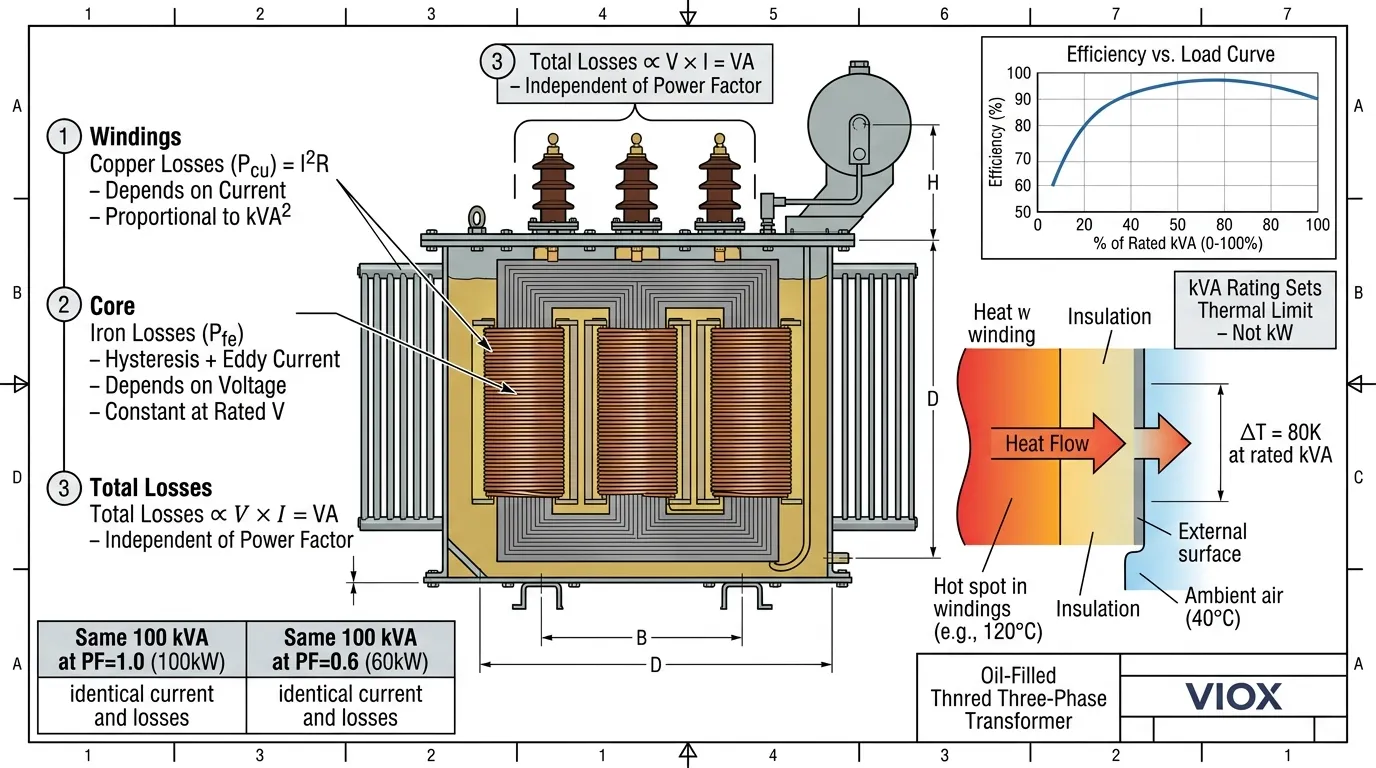
Copper Losses (I²R Losses): These occur in the transformer windings due to the resistance of the copper conductors. Copper losses are proportional to the square of the current flowing through the windings:
Pcu = I² × R
Since current (I) is directly related to apparent power (kVA), copper losses depend entirely on the kVA loading, not the power factor.
Iron Losses (Core Losses): These consist of hysteresis and eddy current losses in the transformer core. Iron losses depend on the voltage applied to the transformer and the frequency:
Pfe ∝ V² × f
Iron losses are essentially constant whenever the transformer is energized, regardless of load.
Total Losses: Since copper losses depend on current and iron losses depend on voltage, the total losses in a transformer are proportional to:
Total Losses ∝ V × I = VA (volt-amperes)
The losses are completely independent of the load power factor. Whether supplying a purely resistive load (PF = 1.0) or a highly inductive load (PF = 0.5), the heat generated within the transformer depends only on the voltage and current—expressed as VA or kVA.
Reason 3: Temperature Rise Correlates with Apparent Power
The temperature rise of a transformer determines its insulation life and safe operating limits. Transformer insulation—typically Class A (105°C), Class B (130°C), Class F (155°C), or Class H (180°C)—degrades with temperature, following the Arrhenius equation where insulation life halves for every 10°C increase above rated temperature.
Since transformer losses (and therefore heat generation) depend on apparent power (kVA), the temperature rise also correlates with kVA, not kW. A transformer supplying 100 kVA at PF = 1.0 (100 kW) generates the same heat as the same transformer supplying 100 kVA at PF = 0.6 (60 kW). In both cases, the current is identical, producing identical copper losses.
How to Calculate Transformer kVA Rating
လျှပ်စစ်စနစ်ဒီဇိုင်းအတွက် ထရန်စဖော်မာအရွယ်အစားကို သင့်လျော်စွာရွေးချယ်ခြင်းသည် အလွန်အရေးကြီးပါသည်။ အရွယ်အစားသေးငယ်လွန်းပါက အပူလွန်ကဲခြင်း၊ သက်တမ်းတိုတောင်းခြင်းနှင့် ပျက်စီးနိုင်ခြေများ ဖြစ်ပေါ်စေပါသည်။ အရွယ်အစားကြီးလွန်းပါက မလိုအပ်သောကုန်ကျစရိတ်များ၊ နေရာပိုယူခြင်းနှင့် ဝန်အားနည်းချိန်တွင် စွမ်းဆောင်ရည်ကျဆင်းခြင်းများ ဖြစ်ပေါ်စေနိုင်ပါသည်။.
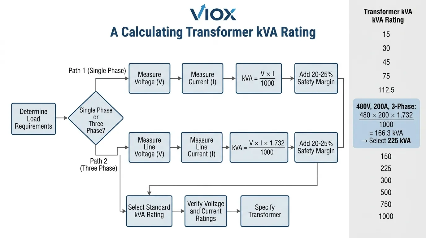
တစ်ပိုင်း ထရန်စဖော်မာ kVA တွက်ချက်ခြင်း
တစ်ပိုင်း ထရန်စဖော်မာများအတွက် kVA အဆင့်သတ်မှတ်ချက်ကို ဗို့အားနှင့် လျှပ်စီးကြောင်းကြားရှိ ရိုးရှင်းသော ဆက်စပ်မှုကို အသုံးပြု၍ တွက်ချက်ပါသည်။
kVA = (V × I) / 1000
Where:
- V = ဗို့အား (volts)
- I = လက်ရှိ (အမ်ပီယာ)
- 1000 = ကီလိုဗို့အား-အမ်ပီယာသို့ ပြောင်းလဲသည့်အချက်
နမူနာတွက်ချက်မှု:
240V တွင် 125A ထောက်ပံ့ပေးသော တစ်ပိုင်း ထရန်စဖော်မာ-
kVA = (240 × 125) / 1000 = 30 kVA
စံ တစ်ပိုင်း ထရန်စဖော်မာ အဆင့်သတ်မှတ်ချက်များသည် R10 ဦးစားပေးနံပါတ်စဉ်အတိုင်း လိုက်နာလေ့ရှိသည်- 5, 10, 15, 25, 37.5, 50, 75, 100, 167, 250, 333, 500 kVA။ နောက်ထပ်စံအရွယ်အစားသို့ အမြဲတမ်း ပင့်တင်ပါ။.
သုံးပိုင်း ထရန်စဖော်မာ kVA တွက်ချက်ခြင်း
သုံးပိုင်း ထရန်စဖော်မာများသည် လျှပ်ကူးပစ္စည်းသုံးခုကြားရှိ အဆင့်ဆက်စပ်မှုကို ထည့်သွင်းတွက်ချက်ရန် လိုအပ်သည်။ တွက်ချက်မှုတွင် 3 ၏ စတုရန်းမြစ် (1.732) ပါဝင်သည်-
kVA = (V × I × 1.732) / 1000
Where:
- V = လိုင်းမှလိုင်းသို့ ဗို့အား (volts)
- I = လိုင်းလျှပ်စီးကြောင်း (amperes)
- 1.732 = √3 (3 ၏ စတုရန်းမြစ်)
နမူနာတွက်ချက်မှု:
480V တွင် 150A ထောက်ပံ့ပေးသော သုံးပိုင်း ထရန်စဖော်မာ-
kVA = (480 × 150 × 1.732) / 1000 = 124.7 kVA
စံအရွယ်အစားသို့ ပင့်တင်ပါ- 150 kVA။.
စံ သုံးပိုင်း ထရန်စဖော်မာ အဆင့်သတ်မှတ်ချက်များတွင်- 15, 30, 45, 75, 112.5, 150, 225, 300, 500, 750, 1000, 1500, 2000, 2500, 3000, 3750, 5000 kVA တို့ပါဝင်သည်။.
kVA မှ Amps သို့ ပြောင်းလဲခြင်း
kVA အဆင့်သတ်မှတ်ချက်ကို သိရှိပြီး အမြင့်ဆုံး လျှပ်စီးကြောင်းပမာဏကို ဆုံးဖြတ်ရန် လိုအပ်သည့်အခါ-
တစ်ပိုင်း-
I = (kVA × 1000) / V
သုံးပိုင်း-
I = (kVA × 1000) / (V × 1.732)
ဥပမာ: A 500 kVA, 480V three-phase transformer:
I = (500 × 1000) / (480 × 1.732) = 601.4 A
ထရန်စဖော်မာ အရွယ်အစား လမ်းညွှန်ချက်များနှင့် အကောင်းဆုံး အလေ့အကျင့်များ
ဘေးကင်းလုံခြုံရေး အနားသတ်ကို ထည့်သွင်းပါ
အင်ဂျင်နီယာဆိုင်ရာ အကောင်းဆုံးအလေ့အကျင့်အရ တွက်ချက်ထားသော အမြင့်ဆုံးဝန်အားထက် 20-25% ဘေးကင်းလုံခြုံရေးအနားသတ်ဖြင့် ထရန်စဖော်မာများကို အရွယ်အစားရွေးချယ်ရန် အကြံပြုထားသည်။ ၎င်းသည် အောက်ပါအချက်များကို ထည့်သွင်းစဉ်းစားသည်-
- ဝန်အားတိုးတက်မှုနှင့် အနာဂတ်တိုးချဲ့မှု
- မော်တာစတင်ချိန်အတွင်း ယာယီဝန်ပိုခြင်း
- ခန့်မှန်းထားသော လျှပ်စီးကြောင်းများနှင့် လက်တွေ့လျှပ်စီးကြောင်းများ ကွဲပြားခြင်း
- ဝန်အားအောက်ရှိ ဗို့အားထိန်းညှိမှုလိုအပ်ချက်များ
ဘေးကင်းလုံခြုံရေး အနားသတ်ဖြင့် တွက်ချက်ခြင်း-
လိုအပ်သော kVA = တွက်ချက်ထားသော ဝန်အား kVA / 0.8
ဥပမာအားဖြင့်၊ တွက်ချက်ထားသော ဝန်အားသည် 200 kVA ဖြစ်ပါက-
လိုအပ်သော kVA = 200 / 0.8 = 250 kVA
ဝန်အား၏ လက္ခဏာများကို ထည့်သွင်းစဉ်းစားပါ
မတူညီသော ဝန်အားအမျိုးအစားများသည် မတူညီသော အရွယ်အစားရွေးချယ်မှုနည်းလမ်းများ လိုအပ်သည်-
| ဝန်အမျိုးအစား | လက္ခဏာများ | အရွယ်အစား ထည့်သွင်းစဉ်းစားခြင်း |
|---|---|---|
| အလင်းရောင် | တည်ငြိမ်သော၊ ခုခံအား | 20% အနားသတ်ဖြင့် လက်ရှိဝန်အားပေါ်တွင် အခြေခံပါ |
| HVAC မော်တာများ | မြင့်မားသောစတင်လက်ရှိ | စီးဝင်နှုန်းလျှပ်စီးကြောင်းအတွက် အရွယ်အစားရွေးချယ်ပါ သို့မဟုတ် ဗို့အားလျှော့ချစနစ်ကို အသုံးပြုပါ |
| ဂဟေဆော်စက်များ | ကြားဖြတ်၊ လျှပ်စီးကြောင်းမြင့်မား | NEC 630 အရ ကွဲပြားမှုအချက်များကို အသုံးပြုပါ |
| ပြောင်းလဲနိုင်သော အရှိန်မောင်းစနစ်များ | မျဉ်းဖြောင့်မဟုတ်သော၊ ဟာမိုနီပါဝင်မှု | 20% ဖြင့် အရွယ်အစားပိုကြီးအောင်ပြုလုပ်ပါ သို့မဟုတ် K-rated ထရန်စဖော်မာများကို အသုံးပြုပါ |
| ဒေတာစင်တာ | သိပ်သည်းဆမြင့်မား၊ အအေးခံခြင်း အရေးကြီးသည် | ပိုလျှံမှုကို စီစဉ်ပါ (N+1 သို့မဟုတ် 2N) |
| Curve D / MPCB | တုန်ခါသောဝန်များ၊ တိုးတက်မှု မသေချာမရေရာမှု | အနာဂတ်တိုးချဲ့မှုအတွက် အရွယ်အစားရွေးချယ်ပါ၊ modular ဒီဇိုင်းကို ထည့်သွင်းစဉ်းစားပါ |
စွမ်းဆောင်ရည် ထည့်သွင်းစဉ်းစားခြင်း
ထရန်စဖော်မာ စွမ်းဆောင်ရည်သည် ဝန်အားနှင့်အညီ ကွဲပြားသည်။ အမြင့်ဆုံးစွမ်းဆောင်ရည်သည် ပုံမှန်အားဖြင့် အဆင့်သတ်မှတ်ထားသော ဝန်အား၏ 50-60% တွင် ဖြစ်ပေါ်သည် ခြောက်သွေ့သော ထရန်စဖော်မာများအတွက် နှင့် ဆီဖြည့်ထားသော ယူနစ်များအတွက် 70-80% ဖြစ်သည်။ အလွန်နည်းပါးသော ဝန်အား (30% အောက်) တွင် အဆက်မပြတ်လည်ပတ်ခြင်းသည် အူတိုင်ဆုံးရှုံးမှုများကြောင့် စွမ်းဆောင်ရည်ညံ့ဖျင်းစေသည်။.
စွမ်းဆောင်ရည်ကို ဤသို့တွက်ချက်နိုင်သည်-
စွမ်းဆောင်ရည် = (ထုတ်လုပ်မှုစွမ်းအား / ထည့်သွင်းမှုစွမ်းအား) × 100 = (kWout / (kWout + ဆုံးရှုံးမှုများ)) × 100
ပုံမှန်ခေတ်မီ ထရန်စဖော်မာ စွမ်းဆောင်ရည်သည် သတ်မှတ်ဝန်အားတွင် 97% မှ 99% အထိ ရှိပြီး၊ ပရီမီယံ စွမ်းဆောင်ရည် ထရန်စဖော်မာများသည် 99% စွမ်းဆောင်ရည်ထက် ကျော်လွန်သည်။.
kVA နှင့် kW: လက်တွေ့ နှိုင်းယှဉ်ဇယား
အောက်ပါဇယားသည် ပုံမှန်စက်မှုလုပ်ငန်းသုံးများအတွက် kVA၊ kW နှင့် ပါဝါအချက်အလက်တို့၏ ဆက်စပ်မှုကို ဖော်ပြထားသည်။
| ထရန်စဖော်မာ အဆင့်သတ်မှတ်ချက် (kVA) | ပါဝါအချက်အလက် (PF) | Real Power (kW) | Reactive Power (kVAR) | ၂၇၀: Application ဥပမာ |
|---|---|---|---|---|
| 100 kVA | 1.0 (ယူနစ်) | 100 kW | 0 kVAR | လျှပ်စစ်အပူပေးစနစ်၊ ခံနိုင်ရည်ရှိသော ဝန်များ |
| 100 kVA | 0.9 | 90 kW | 43.6 kVAR | ရောနှောထားသော စက်မှုဝန်များ |
| 100 kVA | 0.8 | 80 kW | 60 kVAR | မော်တာဝန်များ၊ ပုံမှန်စက်မှုလုပ်ငန်း |
| 100 kVA | 0.7 | 70 kW | 71.4 kVAR | လေးလံသော စက်မှုလုပ်ငန်း၊ မော်တာများစွာ |
| 100 kVA | 0.6 | 60 kW | 80 kVAR | ပါဝါအချက်အလက် မကောင်းခြင်း၊ မပြင်ဆင်ရသေး |
Key Insight: ပါဝါအချက်အလက် မည်သို့ပင်ရှိစေကာမူ၊ ထရန်စဖော်မာ လျှပ်စီးကြောင်းနှင့် အပူချိန်ဝန်သည် တူညီသော kVA အဆင့်သတ်မှတ်ချက်အတွက် တူညီနေကြောင်း သတိပြုပါ။ 100 kVA ထရန်စဖော်မာသည် ယူနစ် PF တွင် 100 kW သို့မဟုတ် 0.6 PF တွင် 60 kW ကို ထောက်ပံ့ပေးသည်ဖြစ်စေ အပြည့်အဝစွမ်းရည်ဖြင့် လုပ်ဆောင်သည်။ ၎င်းသည် kVA သည် သင့်လျော်သော အဆင့်သတ်မှတ်ချက် မက်ထရစ်ဖြစ်ကြောင်း သက်သေပြသည်။.
ထရန်စဖော်မာ အမည်ခံပြား ဒေတာ အဓိပ္ပာယ်ဖွင့်ဆိုခြင်း
ထရန်စဖော်မာ အမည်ခံပြားများကို နားလည်ခြင်းသည် သင့်လျော်သော အသုံးချမှုအတွက် မရှိမဖြစ်လိုအပ်ပါသည်။ စံအမည်ခံပြား ဒေတာတွင် ပါဝင်သည်-
- မူလ အဆင့်သတ်မှတ်ချက်များ- kVA အဆင့်သတ်မှတ်ချက် (ထင်ရှားသော ပါဝါစွမ်းရည်)၊ မူလဗို့အား (ထည့်သွင်းဗို့အား အဆင့်သတ်မှတ်ချက်)၊ မူလလျှပ်စီးကြောင်း (ဝန်အပြည့် လျှပ်စီးကြောင်း)၊ ကြိမ်နှုန်း (ပုံမှန်အားဖြင့် 50 Hz သို့မဟုတ် 60 Hz)
- ဒုတိယ အဆင့်သတ်မှတ်ချက်များ- ဒုတိယဗို့အား (သတ်မှတ်ဝန်အားတွင် ထွက်ရှိဗို့အား)၊ ဒုတိယလျှပ်စီးကြောင်း (ဝန်အပြည့် ထွက်ရှိလျှပ်စီးကြောင်း)၊ တက်ပ်ဗို့အားများ (တက်ပ်ပြောင်းစက် တပ်ဆင်ထားလျှင်)
- စွမ်းဆောင်ရည် ဒေတာ- Impedance ဗို့အား (Z%, ပုံမှန်အားဖြင့် ဖြန့်ဖြူးရေး ထရန်စဖော်မာများအတွက် 4-6%)၊ အပူချိန်မြင့်တက်မှု (ဥပမာ၊ 80°C, 115°C, 150°C), လျှပ်ကာအတန်း (A, B, F, H), ဝန်အမျိုးမျိုးတွင် စွမ်းဆောင်ရည်၊ အသံအဆင့် (ဒက်စီဘယ်)
- ရုပ်ပိုင်းဆိုင်ရာ ဒေတာ- အလေးချိန် (အူတိုင်၊ ကွိုင်၊ စုစုပေါင်း)၊ အတိုင်းအတာများ၊ ချိတ်ဆက်ပုံ (သုံးဆင့်ယူနစ်များအတွက်)၊ အအေးခံနည်းလမ်း (AN, AF, ONAN, ONAF)
အမည်ခံပြားပေါ်ရှိ kVA အဆင့်သတ်မှတ်ချက်သည် သတ်မှတ်ထားသော ပတ်ဝန်းကျင်အပူချိန် (ပုံမှန်အားဖြင့် ပျမ်းမျှ 30°C၊ အမြင့်ဆုံး 40°C) တွင် အပူချိန်မြင့်တက်မှု ကန့်သတ်ချက်ထက် မကျော်လွန်ဘဲ ထရန်စဖော်မာသည် သတ်မှတ်ဗို့အားနှင့် ကြိမ်နှုန်းတွင် သယ်ဆောင်နိုင်သော စဉ်ဆက်မပြတ်ဝန်ကို ကိုယ်စားပြုသည်။.
အသုံးများသော ထရန်စဖော်မာ kVA အဆင့်သတ်မှတ်ချက်များနှင့် အသုံးချမှုများ
ထရန်စဖော်မာများကို လဲလှယ်နိုင်မှုနှင့် စီးပွားရေးစကေးကို ဖွင့်ရန်အတွက် စံပြု kVA အဆင့်သတ်မှတ်ချက်များဖြင့် ထုတ်လုပ်ထားသည်။ အသုံးများသော အဆင့်သတ်မှတ်ချက်များနှင့် ပုံမှန်အသုံးချမှုများတွင် ပါဝင်သည်-
- ဗို့အားနိမ့် ဖြန့်ဖြူးရေး (600V အထိ):
- 5-15 kVA: သေးငယ်သော စီးပွားရေးလုပ်ငန်း၊ လူနေအိမ်၊ ထိန်းချုပ်ပတ်လမ်းများ
- 25-75 kVA: စီးပွားရေး အဆောက်အအုံများ၊ သေးငယ်သော စက်မှုလုပ်ငန်း
- 112.5-300 kVA: စက်မှုစက်ရုံများ၊ ဈေးဝယ်စင်တာများ
- 500-1000 kVA: ကြီးမားသော စက်မှုလုပ်ငန်း၊ ဆေးရုံများ၊ ဒေတာစင်တာများ
- 1500-2500 kVA: အဓိက စက်မှုအဆောက်အအုံများ၊ ဓာတ်အားခွဲရုံများ
- ဗို့အားအလတ် ဖြန့်ဖြူးရေး (35kV အထိ):
- 1000-5000 kVA: မူလဖြန့်ဖြူးရေး၊ ကြီးမားသော အဆောက်အအုံများ
- 7500-15000 kVA: အသုံးဝင်သော ဓာတ်အားခွဲရုံများ၊ စက်မှုဥယျာဉ်များ
ရွေးချယ်ရေး လမ်းညွှန်ချက်များ-
- ချိတ်ဆက်ထားသော ဝန်နှင့် ဘေးကင်းလုံခြုံရေး အနားသတ်နှင့် ကိုက်ညီသော ထရန်စဖော်မာ kVA
- နောက် ၁၀-၁၅ နှစ်အတွက် ဝန်တိုးတက်မှု ခန့်မှန်းချက်များကို ထည့်သွင်းစဉ်းစားပါ။
- စွမ်းအင်ထိရောက်မှု လိုအပ်ချက်များကို အကဲဖြတ်ပါ (USA ရှိ DOE 2016 စံနှုန်းများ)
- ဟာမိုနီပါဝင်မှုကို အကဲဖြတ်ပြီး သတ်မှတ်ပါ K-factor ထရန်စဖော်မာများ လိုအပ်လျှင်
- နှင့် ညှိနှိုင်းပါ ဆားကစ်ကာကွယ်မှု အဆင့်သတ်မှတ်ချက်များ
အတိုချုပ် မေးလေ့ရှိသောမေးခွန်းများ ကဏ္ဍ
မေး- ထရန်စဖော်မာ အဆင့်သတ်မှတ်ချက်များတွင် kVA နှင့် kW အကြား ကွာခြားချက်ကဘာလဲ။
ဖြေ- kVA (ကီလိုဗို့အား-အမ်ပီယာ) သည် ထင်ရှားသော ပါဝါကို ကိုယ်စားပြုသည်—ထရန်စဖော်မာသည် စစ်မှန်သော ပါဝါ (kW) နှင့် တုံ့ပြန်သော ပါဝါ (kVAR) နှစ်ခုလုံးအပါအဝင် ထောက်ပံ့ပေးနိုင်သော စုစုပေါင်းပါဝါဖြစ်သည်။ kW (ကီလိုဝပ်) သည် အသုံးဝင်သောအလုပ်ကို လုပ်ဆောင်သည့် စစ်မှန်သော ပါဝါကိုသာ ကိုယ်စားပြုသည်။ ဆက်စပ်မှုမှာ- kW = kVA × ပါဝါအချက်အလက်။ ထရန်စဖော်မာများသည် kVA တွင် အဆင့်သတ်မှတ်ထားသည်၊ အဘယ်ကြောင့်ဆိုသော် ၎င်းတို့သည် စစ်မှန်သောနှင့် တုံ့ပြန်သော လျှပ်စီးကြောင်းနှစ်ခုလုံးကို ကိုင်တွယ်ရမည်ဖြစ်ပြီး ထုတ်လုပ်သူသည် မည်သည့်ပါဝါအချက်အလက်ဝန်များကို ချိတ်ဆက်မည်ကို ခန့်မှန်း၍မရသောကြောင့်ဖြစ်သည်။.
မေး- ထရန်စဖော်မာ အရွယ်အစားအတွက် kW ကို kVA သို့ မည်သို့ပြောင်းရမည်နည်း။
ဖြေ- kW ကို kVA သို့ပြောင်းရန်၊ kW ကို ပါဝါအချက်အလက်ဖြင့် ပိုင်းခြားပါ- kVA = kW / PF။ ဥပမာအားဖြင့်၊ သင်၏ဝန်သည် ပါဝါအချက်အလက် 0.8 ဖြင့် 400 kW ဖြစ်ပါက၊ အနည်းဆုံး 500 kVA (400 ÷ 0.8) အတွက် အဆင့်သတ်မှတ်ထားသော ထရန်စဖော်မာ လိုအပ်ပါသည်။ အမြဲတမ်း 20% ဘေးကင်းလုံခြုံရေး အနားသတ်ကို ထည့်ပါ- 500 kVA ÷ 0.8 = အနည်းဆုံး 625 kVA ထရန်စဖော်မာ အရွယ်အစား—စံ 750 kVA သို့ ပင့်တင်ပါ။.
မေး။ ကျွန်ုပ်၏ဝန်အားလိုအပ်သည်ထက် kVA ပိုမြင့်သော transformer ကိုသုံးနိုင်ပါသလား။
ဖြေ။ ဟုတ်ကဲ့၊ သင်သည် အရွယ်အစားကြီးသော transformer ကိုသုံးနိုင်သည်။ သို့သော် အဆင့်သတ်မှတ်ထားသော စွမ်းရည်အောက်တွင် သိသိသာသာ လည်ပတ်ခြင်း (ဝန်၏ 30% အောက်တွင် အမြဲတစေလည်ပတ်ခြင်း) သည် core ဆုံးရှုံးမှုများကြောင့် ထိရောက်မှုလျော့နည်းစေသည်။ အများဆုံးထိရောက်မှုသည် အဆင့်သတ်မှတ်ထားသော kVA ၏ 50-80% တွင် ဖြစ်ပေါ်လေ့ရှိသည်။ လုံခြုံရေးအနားသတ်များနှင့် အနာဂတ်တိုးတက်မှုအတွက် တွက်ချက်ထားသော ဝန်ထက် 20-25% ပိုကြီးအောင်ပြုလုပ်ရန် အကြံပြုထားသော်လည်း 100% သို့မဟုတ် ထို့ထက်ပို၍ ကြီးအောင်ပြုလုပ်ခြင်းသည် စွမ်းအင်နှင့် ရင်းနှီးမြှုပ်နှံမှုကို ဖြုန်းတီးစေသည်။.
မေး။ transformer ကို ၎င်း၏ kVA အဆင့်သတ်မှတ်ချက်ထက် ကျော်လွန်၍ ဝန်ပိုတင်ပါက ဘာဖြစ်မလဲ။
ဖြေ။ transformer ကို ဝန်ပိုတင်ခြင်းသည် အပူလွန်ကဲခြင်းကို ဖြစ်စေပြီး၊ ၎င်းသည် လျှပ်ကာအိုမင်းမှုကို အရှိန်မြှင့်စေပြီး ဝန်ဆောင်မှုသက်တမ်းကို လျော့နည်းစေသည်။ Arrhenius ညီမျှခြင်းအရ၊ အဆင့်သတ်မှတ်ထားသော ကန့်သတ်ချက်များထက် 10°C အပူချိန်မြင့်တက်တိုင်း လျှပ်ကာသက်တမ်းသည် ထက်ဝက်ခန့် လျော့နည်းသွားသည်။ ဆက်တိုက်ဝန်ပိုတင်ခြင်းသည် လျှပ်ကာပျက်စီးခြင်း၊ ဝါယာရှော့ဖြစ်ခြင်း၊ transformer မီးလောင်ခြင်း သို့မဟုတ် ကြီးမားသောပျက်စီးခြင်းတို့ကို ဖြစ်စေနိုင်သည်။ ထုတ်လုပ်သူမှ သတ်မှတ်ထားသော အရေးပေါ်ဝန်ပိုတင်ခြင်းမှလွဲ၍ nameplate kVA အဆင့်သတ်မှတ်ချက်ကို ဘယ်တော့မှ မကျော်လွန်ပါနှင့်။.
မေး။ power factor သည် transformer အရွယ်အစားကို မည်သို့အကျိုးသက်ရောက်သနည်း။
ဖြေ။ Power factor သည် kW နှင့် kVA အကြား ဆက်စပ်မှုကို တိုက်ရိုက်အကျိုးသက်ရောက်စေသည်။ Unity power factor (1.0) တွင် kW သည် kVA နှင့် ညီမျှသည်။ Power factor နိမ့်သောအခါ (ပုံမှန်စက်မှုဝန်များ- 0.7-0.9)၊ လိုအပ်သော kVA သည် kW ထက် မြင့်မားသည်။ ဥပမာအားဖြင့်၊ 0.8 PF တွင် 100 kW ဝန်သည် 125 kVA transformer စွမ်းရည် လိုအပ်သည်။ Power factor မကောင်းခြင်းဆိုသည်မှာ တူညီသောအစစ်အမှန်စွမ်းအင်ကို ပေးပို့ရန်အတွက် သင်သည် ပိုကြီးသော (ပိုစျေးကြီးသော) transformer လိုအပ်သည်ဟု ဆိုလိုခြင်းဖြစ်ပြီး၊ ထို့ကြောင့် power factor correction စီးပွားရေးအရ အကျိုးရှိသည်။.
မေး။ သုံးဆင့် transformer kVA ကို တွက်ချက်ရန်အတွက် ဖော်မြူလာကဘာလဲ။
ဖြေ။ သုံးဆင့် transformer များအတွက်- kVA = (ဗို့အား × လျှပ်စီးကြောင်း × 1.732) / 1000၊ ဗို့အားသည် line-to-line ဗို့အားဖြစ်ပြီး၊ လျှပ်စီးကြောင်းသည် line လျှပ်စီးကြောင်းဖြစ်ကာ 1.732 သည် 3 ၏ စတုရန်းမြစ် (√3) ဖြစ်သည်။ ဥပမာအားဖြင့်၊ 480V သုံးဆင့်ကို 200A ဖြင့် ထောက်ပံ့ပေးသော transformer သည်- (480 × 200 × 1.732) / 1000 = 166.3 kVA ဖြစ်မည်—စံ 225 kVA အရွယ်အစားသို့ ပင့်တင်ပါ။.
မေး။ တူညီသော kVA ဝန်တင်မှုဖြင့် မတူညီသော power factor များတွင် transformer ဆုံးရှုံးမှုများသည် တူညီပါသလား။
ဖြေ။ ဟုတ်ကဲ့။ Transformer ကြေးနီဆုံးရှုံးမှုများသည် လျှပ်စီးကြောင်း၏ စတုရန်း (I²R) ပေါ်တွင် မူတည်ပြီး၊ လျှပ်စီးကြောင်းကို kVA (kW မဟုတ်) မှ ဆုံးဖြတ်သောကြောင့်၊ ကြေးနီဆုံးရှုံးမှုများသည် power factor မည်သို့ပင်ရှိစေကာမူ တူညီသော kVA ဝန်တင်မှုအတွက် တူညီပါသည်။ သံဆုံးရှုံးမှုများသည် ဗို့အားပေါ်တွင် မူတည်ပြီး သတ်မှတ်ထားသော ဗို့အားအတွက် အမြဲတမ်းဖြစ်သည်။ ထို့ကြောင့်၊ စုစုပေါင်း transformer ဆုံးရှုံးမှုများ—နှင့် အကျိုးဆက်အနေဖြင့် အပူချိန်မြင့်တက်မှု—သည် kVA ဝန်တင်မှု အမြဲတမ်းရှိနေသောအခါ power factor နှင့် သက်ဆိုင်ခြင်းမရှိပါ။ ဤသည်မှာ transformer များကို kVA ဖြင့် အဆင့်သတ်မှတ်ရခြင်း၏ အခြေခံအကြောင်းရင်းဖြစ်သည်။.
နိဂုံး
Transformer kVA အဆင့်သတ်မှတ်ချက်များကို နားလည်ခြင်းသည် သင့်လျော်သော လျှပ်စစ်စနစ်ဒီဇိုင်းအတွက် အခြေခံဖြစ်သည်။ ၎င်းတို့၏ power factor ကို သိရှိပြီး အတော်လေး အမြဲတမ်းရှိသောကြောင့် kW ဖြင့် အဆင့်သတ်မှတ်ထားသော မော်တာများနှင့် အခြားဝန်များနှင့်မတူဘဲ၊ transformer များသည် မတူညီသော power factor များဖြင့် မည်သည့်ဝန်အမျိုးအစားကိုမဆို နေရာပေးရမည်ဖြစ်သည်။ kVA အဆင့်သတ်မှတ်ချက်သည် ခံနိုင်ရည်ရှိသော အပူပေးစက်များ (PF ≈ 1.0)၊ စက်မှုမော်တာများ (PF ≈ 0.8) သို့မဟုတ် အလွန်အကျွံ လှုံ့ဆော်ပေးသော ဝန်များ (PF < 0.7) ကို transformer က ထောက်ပံ့ပေးသည်ဖြစ်စေ လုံခြုံပြီး ယုံကြည်စိတ်ချရသော လည်ပတ်မှုကို သေချာစေသည့် ကမ္ဘာလုံးဆိုင်ရာ မက်ထရစ်ကို ပေးပါသည်။.
kVA အဆင့်သတ်မှတ်ချက်များအတွက် နည်းပညာအခြေခံသည် transformer ဆုံးရှုံးမှု ယန္တရားများတွင် တည်ရှိသည်- ကြေးနီဆုံးရှုံးမှုများသည် လျှပ်စီးကြောင်းပေါ်တွင် မူတည်ပြီး၊ သံဆုံးရှုံးမှုများသည် ဗို့အားပေါ်တွင် မူတည်ကာ၊ ပေါင်းစပ်မှုသည် ဗို့-အမ်ပီယာ (VA) ပေါ်တွင် မူတည်သည်—ဝပ်ပေါ်တွင် မဟုတ်ပါ။ Transformer အပူချိန်မြင့်တက်မှုသည် လျှပ်ကာသက်တမ်းနှင့် လုံခြုံသောလည်ပတ်မှုကို ဆုံးဖြတ်ပေးပြီး အပူချိန်မြင့်တက်မှုသည် အစစ်အမှန်စွမ်းအင် (kW) ထက် ထင်ရှားသောစွမ်းအင် (kVA) နှင့် ဆက်စပ်နေသောကြောင့် kVA အဆင့်သတ်မှတ်ချက်သည် နည်းပညာအရ မှန်ကန်သော သတ်မှတ်ချက်တစ်ခုဖြစ်သည်။.
အင်ဂျင်နီယာများ၊ ကန်ထရိုက်တာများနှင့် စက်ရုံမန်နေဂျာများအတွက် transformer kVA အဆင့်သတ်မှတ်ချက်များကို မှန်ကန်စွာ တွက်ချက်သတ်မှတ်ခြင်းသည် မရှိမဖြစ်လိုအပ်ပါသည်။ အရွယ်အစားသေးငယ်ခြင်းသည် အချိန်မတိုင်မီ ပျက်ကွက်ခြင်း၊ ဘေးကင်းရေးအန္တရာယ်များနှင့် လုပ်ငန်းလည်ပတ်မှု အနှောင့်အယှက်များဆီသို့ ဦးတည်စေသည်။ အရွယ်အစားကြီးခြင်းသည် ရင်းနှီးမြှုပ်နှံမှုနှင့် စွမ်းအင်ကို ဖြုန်းတီးစေသည်။ ဤဆောင်းပါးတွင် တင်ပြထားသော ဖော်မြူလာများနှင့် လမ်းညွှန်ချက်များ—အကြံပြုထားသော 20-25% ဘေးကင်းရေးအနားသတ်နှင့်အတူ—သည် မည်သည့်အသုံးချမှုအတွက်မဆို အကောင်းဆုံး transformer ရွေးချယ်မှုကို သေချာစေသည်။.
လျှပ်စစ်ပစ္စည်းများ၏ B2B ထုတ်လုပ်သူအနေဖြင့် VIOX Electric သည် transformer သတ်မှတ်ချက်အတွက် ပြည့်စုံသော ပံ့ပိုးကူညီမှုကို ပေးပါသည်။, ကာကွယ်မှု ညှိနှိုင်းခြင်းအတွက်, နှင့် စနစ်ဒီဇိုင်း။ kVA အဆင့်သတ်မှတ်ချက်များကို နားလည်ခြင်းသည် အသိပေးဝယ်ယူမှု ဆုံးဖြတ်ချက်များကို လုပ်ဆောင်နိုင်စေပြီး ကမ္ဘာတစ်ဝှမ်းရှိ စက်မှု၊ စီးပွားဖြစ်နှင့် အခြေခံအဆောက်အအုံ စီမံကိန်းများအတွက် ယုံကြည်စိတ်ချရသော စွမ်းအင်ဖြန့်ဖြူးမှုကို သေချာစေသည်။.
နည်းပညာမှတ်စု- ဤလမ်းညွှန်ပါ kVA တွက်ချက်မှုများနှင့် နည်းပညာဆိုင်ရာအချက်အလက်အားလုံးသည် power transformer များအတွက် IEEE C57.12.00, IEC 60076 နှင့် NEMA ST-20 စံနှုန်းများနှင့် ကိုက်ညီပါသည်။ သီးခြားအသုံးချမှုများအတွက်၊ သက်ဆိုင်ရာစံနှုန်းများနှင့် ထုတ်လုပ်သူ၏စာရွက်စာတမ်းများ၏ နောက်ဆုံးထုတ်ဝေမှုကို အမြဲတမ်းတိုင်ပင်ပါ။ VIOX Electric သည် အကောင်းဆုံးပစ္စည်းကိရိယာရွေးချယ်မှုနှင့် ယုံကြည်စိတ်ချရသော လည်ပတ်မှုကိုသေချာစေရန်အတွက် transformer သတ်မှတ်ချက်နှင့် power system ဒီဇိုင်းအတွက် နည်းပညာပံ့ပိုးမှုကို ပေးပါသည်။.
