
Introduction: The Anatomy of Connection
When specifying terminal blocks for control panels, industrial automation systems, or power distribution applications, engineers often focus on current ratings, voltage classes, and wire compatibility. Yet the true performance—and potential failure points—reside in the terminal block’s internal construction. Understanding terminal block components isn’t academic; it’s essential for making informed specification decisions that affect installation efficiency, long-term reliability, and safety compliance.
Terminal blocks are engineered systems, not mere connectors. Each component serves a specific function: insulating housings prevent electrical shock, conductive busbars carry current, clamping mechanisms maintain contact pressure, and mounting systems ensure mechanical stability. The materials selected for each component—from glass-reinforced polyamide to chrome-nickel spring steel—determine performance under vibration, temperature extremes, and chemical exposure.
This guide provides a systematic breakdown of terminal block construction, examining each component’s function, materials, and standards requirements. Whether you’re designing a new control panel, selecting replacements for maintenance, or evaluating suppliers, this anatomy lesson will help you specify terminal blocks with confidence.
Core Components: What Makes a Terminal Block Work
Every terminal block, regardless of connection technology, consists of four primary functional components working together as an engineered system. Understanding these components—their functions, materials, and interactions—is fundamental to proper specification and application.
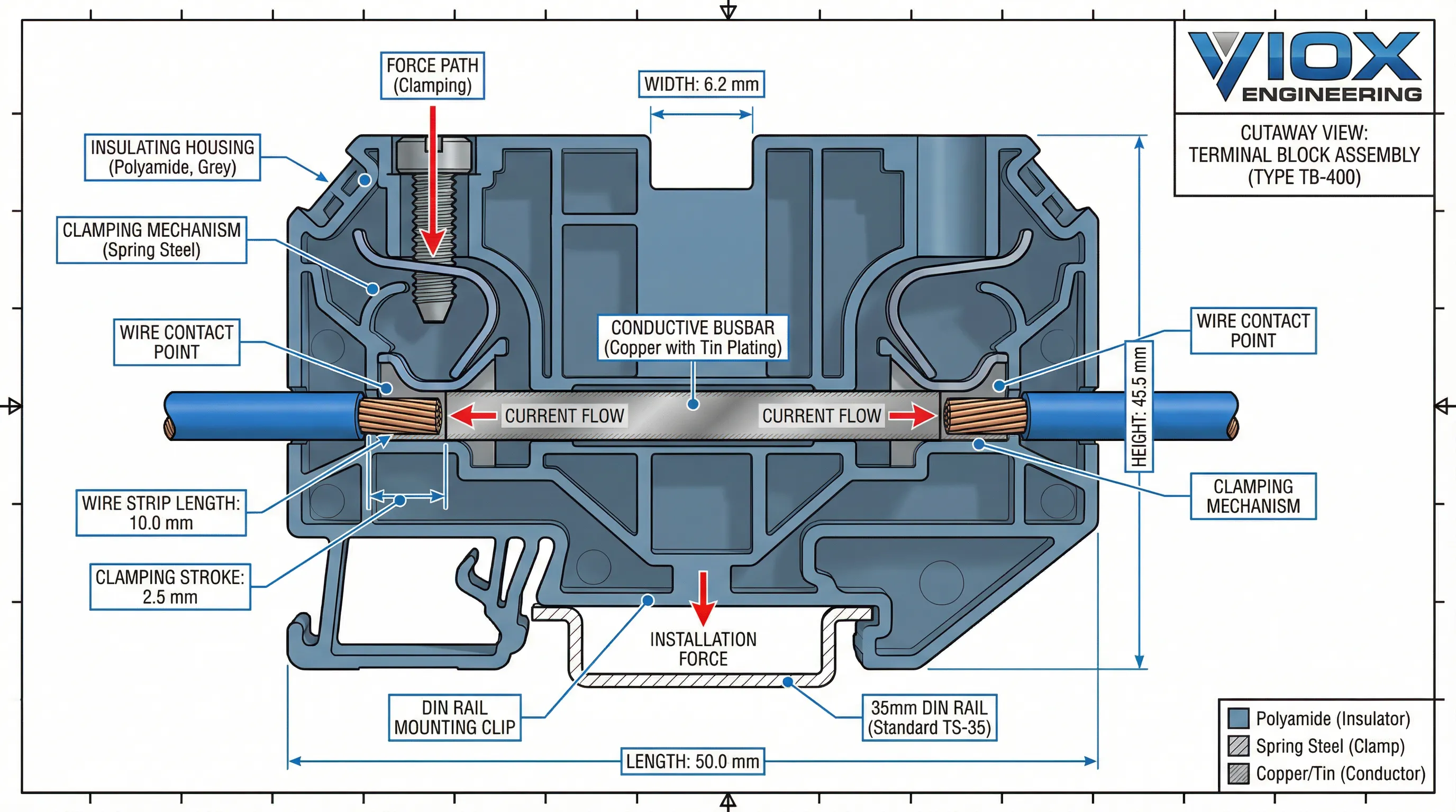
1. Insulating Housing (Body)
The housing serves as the non-conductive frame that contains all internal components while protecting users from electrical shock. More than just a plastic shell, the housing must withstand mechanical stress during installation, maintain dimensional stability across temperature ranges, and provide adequate creepage and clearance distances between conductors.
2. Conductive Busbar (Current-Carrying Element)
This metal “bridge” forms the electrical path between connected wires. The busbar’s material, cross-sectional area, and surface plating determine its current-carrying capacity, resistance, and corrosion resistance. Proper busbar design ensures minimal voltage drop and heat generation under load.
3. Clamping Mechanism
The clamping mechanism physically secures the wire to the busbar, maintaining constant contact pressure over time. Different technologies—screw, spring-cage, push-in—offer trade-offs between installation speed, vibration resistance, and wire compatibility.
4. Mounting System
Mounting systems attach terminal blocks to DIN သံလမ်း, panels, or PCBs, providing mechanical stability and proper alignment. The mounting method affects installation density, accessibility for wiring, and resistance to vibration or mechanical shock.
These components work in concert: the housing insulates, the busbar conducts, the clamp secures, and the mounting system stabilizes. Material selection for each component creates a terminal block optimized for specific environmental conditions and performance requirements.
Table 1: Terminal Block Component Functions and Materials
| အစိတ်အပိုင်း | Primary Function | အသုံးများသောပစ္စည်းများ | Standards Requirements |
|---|---|---|---|
| Insulating Housing | Electrical insulation, mechanical protection, environmental resistance | Polyamide 6.6 (PA66), PBT, Polycarbonate (PC) | UL 94V-0 flame rating, IEC 60664-1 creepage/clearance |
| Conductive Busbar | Current carrying, low resistance path | Electrolytic copper, brass (tin/nickel/silver plated) | IEC 60947-7-1 current rating, temperature rise limits |
| Clamping Mechanism ၊ | Secure wire connection, maintain contact pressure | Screw: zinc-plated steel; Spring: chrome-nickel steel; Push-in: stainless steel | Mechanical endurance (IEC 60947-7-1), vibration resistance (IEC 60068-2-6) |
| တပ်ဆင်ခြင်းစနစ် | Mechanical attachment, alignment, vibration resistance | Spring-steel clips, screw-type feet, snap-on designs | DIN rail standards (IEC 60715), retention force requirements |
| Auxiliary Parts | Additional functionality, marking, protection | Jumpers (copper/brass), end plates (PA66/PBT), marking tags | Compatibility with main components, secondary standards |
Housing & Insulation: Safety and Durability
The insulating housing is the terminal block’s first line of defense against electrical shock, environmental hazards, and mechanical damage. More than just a plastic shell, the housing must meet precise engineering requirements for dielectric strength, flame resistance, mechanical toughness, and dimensional stability across operating temperatures.
Material Selection: Engineering Thermoplastics vs. Thermosets
Industrial terminal blocks primarily use three engineering thermoplastics, each with distinct properties:
Polyamide 6.6 (Nylon 66) – The industry standard for general-purpose applications:
- Key Properties: High mechanical strength, flexibility (resists cracking during installation), excellent heat resistance (typically 125°C continuous)
- အသုံးများတယ်။: Glass-reinforced versions (PA66 GF30) for added stiffness and dimensional stability
- Flame Rating: UL 94V-0 standard for self-extinguishing behavior
PBT (Polybutylene Terephthalate) – The choice for precision and moisture resistance:
- Key Properties: Low moisture absorption (<0.1%), exceptional dimensional stability, good chemical resistance
- အသုံးများတယ်။: High-humidity environments, applications requiring tight tolerances
- အပူချိန်အကွာအဝေး: Typically 130-140°C continuous
Polycarbonate (PC) – For transparency and impact resistance:
- Key Properties: Excellent clarity, high impact strength, good thermal stability
- ကန့်သတ်ချက်များ: Sensitive to certain chemicals (solvents, alkalis)
- အသုံးများတယ်။: Transparent covers, applications requiring visual inspection
Critical Design Considerations
Creepage and Clearance Distances: The housing must maintain minimum distances between conductors based on voltage ratings (IEC 60664-1). Higher voltage blocks require larger physical dimensions.
Temperature Class: Housing materials must withstand maximum operating temperatures without deformation or loss of dielectric properties. Industrial applications typically require 105°C minimum, with 125°C becoming standard for modern equipment.
Flame Retardancy: UL 94V-0 certification indicates the material self-extinguishes within 10 seconds and doesn’t drip flaming particles—essential for control panel safety.
ဓာတုခံနိုင်ရည်: Terminal blocks in chemical plants, marine environments, or food processing must resist oils, solvents, acids, and alkalis without degradation.
The housing’s material selection directly impacts installation experience (flexibility vs. rigidity), long-term reliability (moisture absorption), and safety compliance (flame ratings).
Clamping Mechanisms: Screw, Spring, and Push-in Technologies
The clamping mechanism is the terminal block’s active component—the interface where wire meets busbar. Three primary technologies dominate industrial applications, each with distinct operating principles, advantages, and ideal use cases.
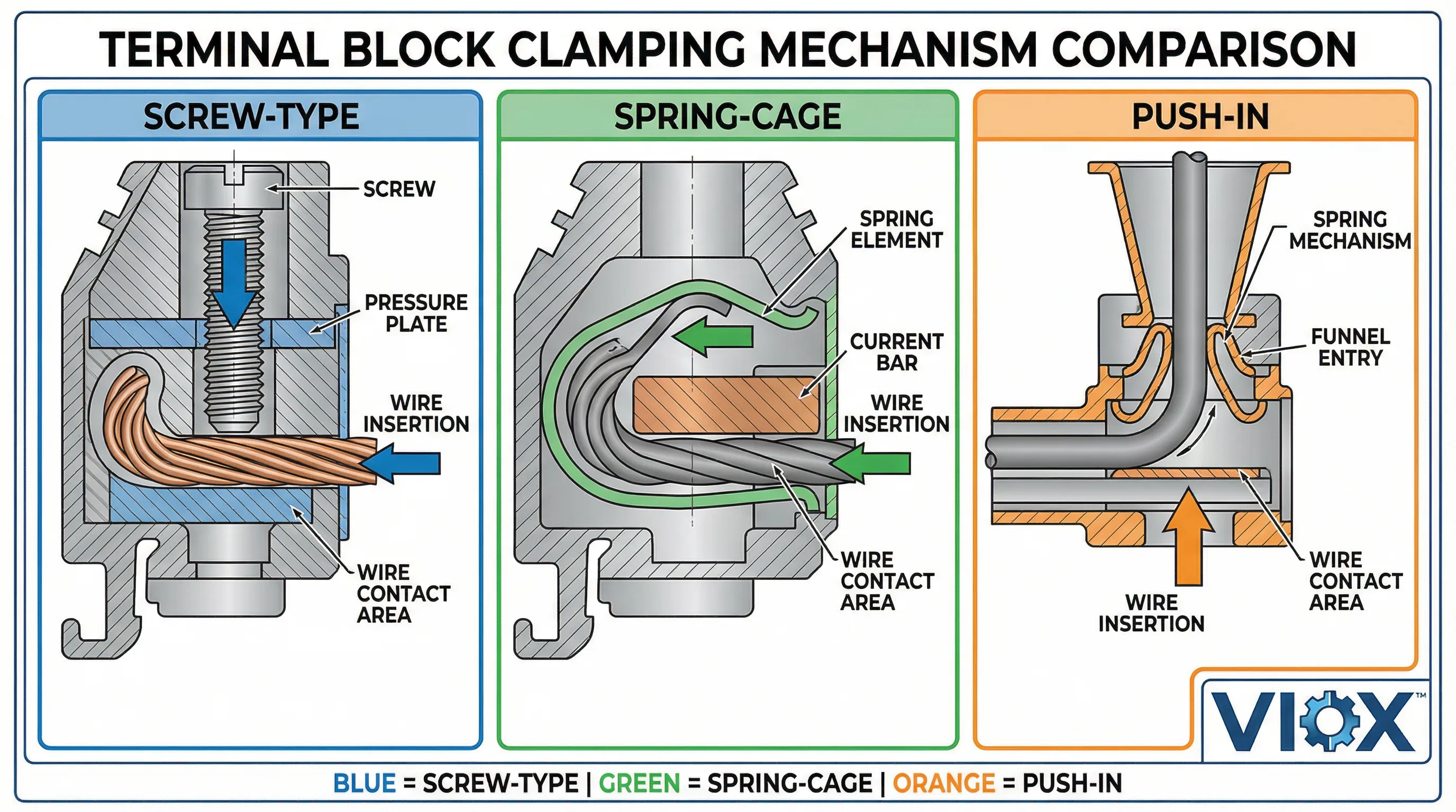
1. Screw-Type Clamping
လည်ပတ်မှုနိယာမ: A hardened steel screw compresses the wire against the busbar through direct mechanical force. The screw applies pressure via a metal cage or pressure plate that distributes force across the conductor.
အဓိကအစိတ်အပိုင်းများ:
- ဝက်အူ: Zinc-plated or galvanized steel for corrosion resistance
- Pressure Plate/Cage: Brass or steel to distribute clamping force
- Threaded Insert: Brass or steel for durability
အားသာချက်များ:
- Universal wire compatibility (solid, stranded, fine-stranded)
- High clamping force for large conductors
- Visual verification of connection tightness
- Field serviceable with standard tools
ကန့်သတ်ချက်များ:
- Installation time (requires torque-controlled tools)
- Vibration susceptibility (requires periodic retightening)
- Torque sensitivity (overtightening damages conductors)
2. Spring-Cage Clamping (CAGE CLAMP®)
လည်ပတ်မှုနိယာမ: A chrome-nickel spring steel element provides constant pressure on the conductor. Insertion requires opening the spring with a tool; removal similarly requires tool operation.
အဓိကအစိတ်အပိုင်းများ:
- Spring Element: Chrome-nickel steel for elasticity and corrosion resistance
- Current Bar: Electrolytic copper with tinned surface
- Operating Lever: Integrated tool access point
အားသာချက်များ:
- Maintenance-free (constant spring pressure)
- Vibration-proof connections
- Fast installation after initial tool use
- Wide conductor range (0.08–35 mm² / 28–2 AWG)
ကန့်သတ်ချက်များ:
- Requires tool for insertion/removal
- Limited to compatible wire types
- Higher initial component cost
3. Push-in Spring Clamping
လည်ပတ်မှုနိယာမ: A spring mechanism allows tool-less insertion of rigid conductors. The conductor’s rigidity provides counterforce against the spring; removal requires a tool.
အဓိကအစိတ်အပိုင်းများ:
- Spring Mechanism: Stainless steel or chrome-nickel alloy
- Funnel Entry: Guides conductor to contact point
- Separate Clamping Units: Prevents multiple conductors per point
အားသာချက်များ:
- Tool-less installation (significant time savings)
- Positive connection feedback
- Compact design for high density
- Ideal for rigid or ferruled conductors
ကန့်သတ်ချက်များ:
- Requires tool for removal
- Limited to specific conductor types
- Not suitable for all stranded wires without ferrules
Technology Selection Matrix
Each clamping technology excels in specific applications:
- Screw-type: High-current power distribution, mixed wire types, field service requirements
- Spring-cage: Vibration environments, maintenance-free applications, wide conductor ranges
- Push-in: High-volume panel assembly, time-critical installations, rigid conductor applications
Table 2: Clamping Mechanism Comparison
| အင်္ဂါ | Screw-Type | Spring-Cage | Push-in |
|---|---|---|---|
| စစ်ဆင်ရေး | Tool required (torque driver) | Tool for insertion/removal | Tool-less insertion, tool removal |
| ဝိုင်ယာ လိုက်ဖက်မှု | Universal (solid, stranded, fine-stranded) | Wide range (0.08-35 mm²) | မာကျောသော လျှပ်ကူးပစ္စည်းများ (အခဲ၊ ကြိုးထုံးပါသော ကြိုး) |
| တပ်ဆင်မှုအမြန်နှုန်း | နှေးကွေးသည် (torque ထိန်းချုပ်မှု လိုအပ်သည်) | အလယ်အလတ် (ကိရိယာ အသုံးပြုရန် လိုအပ်သည်) | မြန်ဆန်သည် (ကိရိယာ မလိုအပ်ပါ) |
| တုန်ခါမှု ခုခံမှု | အခါအားလျော်စွာ ပြန်လည် တင်းကျပ်ရန် လိုအပ်သည် | အလွန်ကောင်းမွန်သည် (စဉ်ဆက်မပြတ် စပရိန် ဖိအား) | ကောင်းမွန်သည် (စပရိန် တပ်ဆင်ထားသည်) |
| ပြုပြင်ထိန်းသိမ်းမှု | လုပ်ငန်းခွင်၌ ပြုပြင်နိုင်သည်၊ စစ်ဆေးရန် လိုအပ်သည် | ပြုပြင်ထိန်းသိမ်းမှု မလိုအပ်ပါ | ပြုပြင်ထိန်းသိမ်းမှု နည်းပါးသည် |
| စံပြအသုံးချမှုများ | လျှပ်စီးကြောင်းအား များပြားစွာ ဖြန့်ဖြူးခြင်း၊ ဝါယာကြိုး အမျိုးအစားများ ရောနှောခြင်း | တုန်ခါမှုရှိသော ပတ်ဝန်းကျင်များ၊ ပြုပြင်ထိန်းသိမ်းမှု မလိုအပ်သော အခြေအနေများ | အမြောက်အမြား panel တပ်ဆင်ခြင်း၊ အချိန်နှင့်အမျှ အရေးကြီးသော တပ်ဆင်မှုများ |
| စံချိန်စံညွှန်းများ လိုက်နာခြင်း။ | IEC 60947-7-1, UL 1059 (Group C) | IEC 60947-7-1, UL 1059 (Group B/C) | IEC 60947-7-1, UL 1059 (Group B/C) |
ချိတ်ဆက်သည့် ယန္တရား ရွေးချယ်မှုသည် တပ်ဆင်မှု စွမ်းဆောင်ရည်၊ ရေရှည် တည်ငြိမ်မှုနှင့် စက်ပစ္စည်း သက်တမ်းတစ်လျှောက် ကုန်ကျစရိတ် စုစုပေါင်းကို တိုက်ရိုက် သက်ရောက်မှု ရှိသည်။.
လျှပ်ကူးပစ္စည်း ထိတွေ့မှုနှင့် လျှပ်စီးကြောင်း လမ်းကြောင်း
လျှပ်ကူးပစ္စည်း ထိတွေ့မျက်နှာပြင်သည် လျှပ်စစ် စွမ်းဆောင်ရည်နှင့် စက်ပိုင်းဆိုင်ရာ ဒီဇိုင်းတို့ တွေ့ဆုံရာ နေရာဖြစ်သည်။ သင့်လျော်သော ချိတ်ဆက်မှုတစ်ခုသည် လုံလောက်သော ထိတွေ့ဧရိယာ၊ သင့်လျော်သော ဖိအားနှင့် terminal block ၏ ဝန်ဆောင်မှု သက်တမ်းတစ်လျှောက် ခုခံအားနည်းသော ပစ္စည်းများ လိုအပ်သည်။.
ထိတွေ့ပစ္စည်းများနှင့် သတ္တုရည် သုတ်ခြင်း
အခြေခံပစ္စည်းများ:
- Electrolytic Copper: လျှပ်ကူးနိုင်စွမ်း အမြင့်ဆုံး (100% IACS)၊ လျှပ်စီးကြောင်းအား များပြားသော အသုံးပြုမှုများအတွက် အကောင်းဆုံး
- Brass (Copper-Zinc): ကောင်းမွန်သော လျှပ်ကူးနိုင်စွမ်း (28% IACS) နှင့် စက်ပိုင်းဆိုင်ရာ ခိုင်ခံ့မှု ပိုမိုကောင်းမွန်ခြင်း
- Phosphor Bronze: ချိတ်ဆက်သည့် ယန္တရားများအတွက် အလွန်ကောင်းမွန်သော စပရိန် ဂုဏ်သတ္တိများ
မျက်နှာပြင် သတ္တုရည် သုတ်ခြင်း:
- Tin (Sn): အသုံးပြုမှု အထွေထွေအတွက် စံသတ်မှတ်ထားသော သတ္တုရည် သုတ်ခြင်း၊ ကြေးနီ အောက်ဆီဂျင်ဖြစ်ခြင်းကို ကာကွယ်ပေးသည်
- Nickel (Ni): ပိုမိုကောင်းမွန်သော သံချေးတက်ခြင်းကို ခံနိုင်ရည်ရှိခြင်း၊ အပူချိန် မြင့်မားမှုကို ခံနိုင်ရည်ရှိခြင်း
- Silver (Ag): ဗို့အားမြင့် အသုံးပြုမှုများအတွက် သာလွန်ကောင်းမွန်သော လျှပ်ကူးနိုင်စွမ်းနှင့် အောက်ဆီဂျင်ဖြစ်ခြင်းကို ခံနိုင်ရည်ရှိခြင်း
- Gold (Au): အနည်းဆုံး ထိတွေ့ခုခံမှု လိုအပ်သော signal-level အသုံးပြုမှုများအတွက်သာ ကန့်သတ်ထားသည်
ထိတွေ့ဖိအားနှင့် ခုခံမှု
အကောင်းဆုံး ဆက်သွယ်မှု ဖိအား:
- မာကျောသော လျှပ်ကူးပစ္စည်းများ: ထိတွေ့မှတ်တစ်ခုလျှင် 15-25 N (newtons)
- ကြိုးထုံးပါသော လျှပ်ကူးပစ္စည်းများ: မျက်နှာပြင် မညီမညာဖြစ်ခြင်းကို လျော်ကြေးပေးရန် 20-30 N
- Ferrules ပါသော အလွန်သေးငယ်သော ကြိုးထုံးများ: လုံခြုံသော crimped ချိတ်ဆက်မှုများအတွက် 25-35 N
ဆက်သွယ်ရန် ခုခံမှု:
- အရည်အသွေးမြင့် terminal block များသည် ချိတ်ဆက်မှုတစ်ခုလျှင် <0.5 mΩ ကို ထိန်းသိမ်းထားသည်
- အပူချိန်နှင့်အတူ ခုခံမှု တိုးလာသည် (ပုံမှန်အားဖြင့် တစ်ဒီဂရီစင်တီဂရိတ်လျှင် 0.4%)
- သင့်လျော်သော torque/spring အားသည် အချိန်ကြာလာသည်နှင့်အမျှ ခုခံမှု ပြောင်းလဲခြင်းကို အနည်းဆုံးဖြစ်စေသည်
လျှပ်စီးကြောင်း လမ်းကြောင်း ဒီဇိုင်း
ဖြတ်ပိုင်းဧရိယာ:
- Busbar အရွယ်အစားများသည် အပူချိန် အလွန်အကျွံ မမြင့်တက်ဘဲ သတ်မှတ်ထားသော လျှပ်စီးကြောင်းကို ထောက်ပံ့ပေးရမည်
- ပုံမှန် ဒီဇိုင်း- စဉ်ဆက်မပြတ် လျှပ်စီးကြောင်း 5-8A လျှင် 1 mm² ဖြတ်ပိုင်း (ကြေးနီ)
- ပတ်ဝန်းကျင် အပူချိန် 40°C အထက်တွင် လျှော့ချရန် လိုအပ်သည်
အပူပျံ့ခြင်း။:
- ထိတွေ့ခုခံမှုသည် အပူကို ထုတ်ပေးသည် (P = I²R)
- အိမ်ရာ ဒီဇိုင်းသည် ပတ်ဝန်းကျင်သို့ အပူလွှဲပြောင်းမှုကို ခွင့်ပြုရမည်
- Multi-level block များသည် အပူပိုင်းဆိုင်ရာ ထည့်သွင်းစဉ်းစားမှုများ လိုအပ်သည်
ဝါယာကြိုး လိုက်ဖက်ညီမှု အချက်များ
လျှပ်ကူးပစ္စည်း အမျိုးအစား:
- မာကျောသော ဝါယာကြိုး: screw-type terminal များအတွက် အကောင်းဆုံး၊ ဖိအားအောက်တွင် ပုံသဏ္ဍာန်ကို ထိန်းသိမ်းထားသည်
- ကြိုးထုံးပါသော ဝါယာကြိုး: ချိတ်ဆက်အား ပိုမိုမြင့်မားရန် လိုအပ်သည်၊ ferrules မှ အကျိုးကျေးဇူး ရရှိသည်
- အလွန်သေးငယ်သော ကြိုးထုံးများ: spring/push-in terminal များဖြင့် ferrules ကို အသုံးပြုရမည်
အရှည်:
- မလုံလောက်သော အခွံခွာခြင်းသည် လျှပ်ကာကို ချိတ်ဆက်ဖိအားနှင့် ထိတွေ့စေသည်
- အခွံ အလွန်အကျွံခွာခြင်းသည် ထိတွေ့ဧရိယာကို လျော့နည်းစေပြီး အောက်ဆီဂျင်ဖြစ်နိုင်ခြေကို တိုးစေသည်
- ထုတ်လုပ်သူ၏ သတ်မှတ်ချက်များသည် အကောင်းဆုံး အခွံခွာအရှည်ကို ပုံမှန်အားဖြင့် ညွှန်ပြသည်။
လျှပ်ကူးပစ္စည်း ထိတွေ့မျက်နှာပြင်သည် terminal block ၏ လျှပ်စစ် “လည်ပင်းညှစ်ရာ” ကို ကိုယ်စားပြုသည်။ သင့်လျော်သော ပစ္စည်းရွေးချယ်မှု၊ လုံလောက်သော ဖိအားနှင့် သင့်လျော်သော ဝါယာကြိုးပြင်ဆင်မှုတို့သည် အနည်းဆုံး ခုခံမှု၊ အပူထုတ်လုပ်မှု လျော့နည်းခြင်းနှင့် ရေရှည်တည်ငြိမ်မှုကို သေချာစေသည်။.
တပ်ဆင်ခြင်းစနစ်များ- DIN Rail နှင့် Panel ပေါင်းစပ်ခြင်း
တပ်ဆင်ခြင်းစနစ်များသည် စက်ပိုင်းဆိုင်ရာ တည်ငြိမ်မှုကို ပေးစွမ်းပြီး သင့်လျော်သော ချိန်ညှိမှုကို သေချာစေကာ တပ်ဆင်သိပ်သည်းဆကို အထောက်အကူပြုသည်။ DIN rail တပ်ဆင်ခြင်း၊ panel တပ်ဆင်ခြင်း သို့မဟုတ် PCB တပ်ဆင်ခြင်းကြား ရွေးချယ်မှုသည် တပ်ဆင်ခြင်း လုပ်ငန်းစဉ်၊ ပြုပြင်ထိန်းသိမ်းမှု အသုံးပြုနိုင်စွမ်းနှင့် တုန်ခါမှု သို့မဟုတ် စက်ပိုင်းဆိုင်ရာ ထိခိုက်မှုတို့ကို ခံနိုင်ရည်ရှိမှုအပေါ် သက်ရောက်မှုရှိသည်။.
DIN Rail တပ်ဆင်ခြင်း စံနှုန်းများ
မူလ DIN Rail အမျိုးအစားများ:
- Top Hat Rail (TH35): အကျယ် 35mm၊ အမြင့် 7.5mm - ဥရောပစံနှုန်း (IEC 60715)
- G-Rail (G32): အကျယ် 32mm - မြောက်အမေရိကစံနှုန်း
- Mini Rail (15mm): ကျစ်လစ်သိပ်သည်းသော အသုံးချမှုများအတွက်
တပ်ဆင်ခြင်း ယန္တရားများ:
- Spring-Loaded Clip: ကိရိယာများမပါဘဲ လျင်မြန်စွာ တပ်ဆင်နိုင်ခြင်း၊ တုန်ခါမှုကို ခံနိုင်ရည်ရှိခြင်း
- Screw-Type Foot: အပြုသဘောဆောင်သော စက်ပိုင်းဆိုင်ရာ လော့ခ်၊ ပိုမိုမြင့်မားသော ထိန်းသိမ်းအား
- Snap-On Design: အသံပမာဏများသော အသုံးချမှုများအတွက် ကိရိယာမလိုဘဲ တပ်ဆင်နိုင်ခြင်း
အရေးကြီးသော တပ်ဆင်ခြင်းဆိုင်ရာ ထည့်သွင်းစဉ်းစားချက်များ
တုန်ခါမှု ခုခံမှု:
- Spring-clip ဒီဇိုင်းများသည် တုန်ခါမှုအောက်တွင် တင်းအားကို ထိန်းသိမ်းထားသည်။
- Screw-type mounts များသည် locking washers သို့မဟုတ် thread-locking compounds များ လိုအပ်သည်။
- DIN rail ပစ္စည်း (သံမဏိနှင့် အလူမီနီယမ်) သည် damping လက္ခဏာများကို သက်ရောက်မှုရှိသည်။
အပူချိန်ပြောင်းလဲခြင်း:
- Terminal block နှင့် DIN rail ပစ္စည်းများသည် လိုက်ဖက်ညီသော ချဲ့ထွင်မှုကိန်းဂဏန်းများ ရှိရမည်။
- ပလတ်စတစ်အိမ်များသည် သတ္တုရထားများထက် ပိုမိုကျယ်ပြန့်သည် (ပုံမှန်အားဖြင့် 8-10x)
- ဒီဇိုင်းသည် ဖိအားစုစည်းမှုမရှိဘဲ ကွဲပြားသော ချဲ့ထွင်မှုကို နေရာချထားပေးရမည်။
တပ်ဆင်ခြင်း သိပ်သည်းဆ:
- Pitch dimensions သည် ရထားတစ်မီတာလျှင် block အရေအတွက်ကို ဆုံးဖြတ်သည်။
- Multi-level block များသည် သိပ်သည်းဆကို တိုးစေသော်လည်း အပူစွန့်ထုတ်မှုကို လျှော့ချပေးသည်။
- ဝါယာကြိုးကွေးညွှတ်ခြင်း အချင်းဝက်အတွက် အနည်းဆုံး နေရာလွတ်လိုအပ်ချက်များ
Panel နှင့် PCB တပ်ဆင်ခြင်း အခြားရွေးချယ်စရာများ
Panel Mounting:
- အကာအရံ backplane သို့ တိုက်ရိုက်ဝက်အူတပ်ဆင်ခြင်း
- တူးထားသော/ထိပုတ်ထားသော အပေါက်များ သို့မဟုတ် တပ်ဆင်ခြင်းကွင်းများ လိုအပ်သည်။
- အမြင့်ဆုံး စက်ပိုင်းဆိုင်ရာ တည်ငြိမ်မှုကို ပေးစွမ်းသည်။
PCB တပ်ဆင်ခြင်း:
- Through-hole သို့မဟုတ် surface-mount ဒီဇိုင်းများ
- Pitch သည် PCB grid နှင့် ကိုက်ညီရမည် (ပုံမှန်အားဖြင့် 2.54mm, 5.08mm, 7.62mm)
- Wave soldering လိုက်ဖက်ညီမှု လိုအပ်ချက်များ
Hybrid စနစ်များ:
- Pluggable PCB connectors ပါသော DIN rail တပ်ဆင်ထားသော terminal block များ
- Field-wiring access ပါသော Panel-mounted terminal strips များ
စံချိန်စံညွှန်းများ လိုက်နာခြင်း။
DIN Rail စံနှုန်းများ:
- IEC 60715: ရထားများပေါ်တွင် ဗို့အားနည်းသော switchgear ၏ အရွယ်အစားနှင့် တပ်ဆင်ခြင်း
- အဆိုပါ ၅၀၈A: စက်မှုထိန်းချုပ်မှု panel များ (terminal block တပ်ဆင်ခြင်းအပါအဝင်)
- EN 50022: TH35 rail သတ်မှတ်ချက်များ
စက်ပိုင်းဆိုင်ရာ စမ်းသပ်ခြင်း။:
- တုန်ခါမှုခံနိုင်ရည် (IEC 60068-2-6)
- Shock ခံနိုင်ရည် (IEC 60068-2-27)
- စက်ပိုင်းဆိုင်ရာ ခံနိုင်ရည် (IEC 60947-7-1)
တပ်ဆင်ခြင်းစနစ်သည် terminal block ၏ စက်ပိုင်းဆိုင်ရာ အခြေခံအုတ်မြစ်ကို ကိုယ်စားပြုသည်။ သင့်လျော်သော ရွေးချယ်မှုသည် တည်ငြိမ်သော ချိတ်ဆက်မှုများကို သေချာစေပြီး ပြုပြင်ထိန်းသိမ်းမှု အသုံးပြုနိုင်စွမ်းကို အထောက်အကူပြုကာ စက်ပစ္စည်း၏ လည်ပတ်သက်တမ်းတစ်လျှောက်လုံး ပတ်ဝန်းကျင်ဆိုင်ရာ ဖိစီးမှုများကို ခံနိုင်ရည်ရှိသည်။.
နည်းပညာဆိုင်ရာ သတ်မှတ်ချက်များနှင့် အဆင့်သတ်မှတ်ချက်များ
Terminal block စွမ်းဆောင်ရည်ကို လျှပ်စစ်၊ စက်ပိုင်းဆိုင်ရာနှင့် ပတ်ဝန်းကျင်ဆိုင်ရာ စွမ်းဆောင်ရည်များကို သတ်မှတ်သည့် စံပြုသတ်မှတ်ချက်များမှတစ်ဆင့် တိုင်းတာသည်။ ဤအဆင့်သတ်မှတ်ချက်များကို နားလည်ခြင်းသည် စက်မှုလုပ်ငန်းစံနှုန်းများနှင့်အညီ သင့်လျော်သောအသုံးချမှုကို သေချာစေသည်။.
လျှပ်စစ်အဆင့်သတ်မှတ်ချက်များ
လက်ရှိ အဆင့်သတ်မှတ်ချက် (Amperage):
- အပူချိန်ကန့်သတ်ချက်များထက် မကျော်လွန်ဘဲ အများဆုံးဆက်တိုက်စီးဆင်းနိုင်သော လျှပ်စီးကြောင်းဖြင့် သတ်မှတ်သည်။
- ပုံမှန်အားဖြင့် 40°C ပတ်ဝန်းကျင်အပူချိန်တွင် အဆင့်သတ်မှတ်သည်။
- ပိုမိုမြင့်မားသော ပတ်ဝန်းကျင်အပူချိန်များအတွက် လျှော့ချရန် လိုအပ်သည် (ပုံမှန်အားဖြင့် 40°C အထက် တစ်ဒီဂရီလျှင် 0.8% လျှော့ချရန် လိုအပ်သည်)
ဗို့ပးခ်က္:
- လည်ပတ်ဗို့အား: အများဆုံး ဆက်တိုက်လည်ပတ်နိုင်သော ဗို့အား (ပုံမှန်အားဖြင့် 600V AC/DC)
- Impulse ဗို့အား: ခဏတာခံနိုင်သော ဗို့အား (ပုံမှန်အားဖြင့် 1.2/50µs အတွက် 6kV)
- လျှပ်ကာ ဗို့အား: လျှပ်ကူးပစ္စည်းများနှင့် တပ်ဆင်ရထားကြား ဗို့အား (ပုံမှန်အားဖြင့် 2500V AC)
ဆက်သွယ်ရန် ခုခံမှု:
- တစ်ဆက်သွယ်မှုလျှင် milliohms (mΩ) ဖြင့် တိုင်းတာသည်။
- အရည်အသွေးကောင်းမွန်သော terminal block များ- <0.5 mΩ မူလခုခံမှု
- အပူချိန်နှင့် အိုမင်းခြင်းနှင့်အတူ တိုးလာသည်။
စက်ပိုင်းဆိုင်ရာသတ်မှတ်ချက်များ
ဝါယာကြိုး အကွာအဝေး:
- AWG (အမေရိကန်ဝါယာဂေ့ခ်ျ) နှင့် မီလီမီတာစတုရန်း (mm²) ဖြင့် ဖော်ပြသည်။
- ပုံမှန်စက်မှုလုပ်ငန်းအကွာအဝေးများ: 22-10 AWG (0.5-6 mm²) မှ 4-2/0 AWG (25-95 mm²)
- ခိုင်မာသော နှင့် ကြိုးထုံး နှစ်မျိုးလုံးကို လက်ခံနိုင်ရမည်။
ဇယား ၃: ဝါယာဂေ့ခ်ျလိုက်ဖက်မှုနှင့် လျှပ်စီးကြောင်းနှုန်းများ
| ကြိုးအရွယ်အစား (AWG) | ဖြတ်ပိုင်း (mm²) | ခိုင်မာသောကြိုး | ကြိုးထုံး | Ferrules လိုအပ်ပါသလား | ပုံမှန်လက်ရှိ အဆင့်သတ်မှတ်မှု |
|---|---|---|---|---|---|
| 22-18 | 0.5-1.0 | ဟုတ်ကဲ့ | ဟုတ်ကဲ့ (စပရိန်/တွန်းထည့်) | ရွေးချယ်နိုင်သည် (တွန်းထည့်) | 5-15A |
| 16-14 | 1.5-2.5 | ဟုတ်ကဲ့ | ဟုတ်ကဲ့ | အကြံပြုသည်။ | 20-32A |
| 12-10 | 4.0-6.0 | ဟုတ်ကဲ့ | ဟုတ်ကဲ့ | အကြံပြုသည်။ | 30-50A |
| 8-6 | 10-16 | ဟုတ်ကဲ့ | အကန့်အသတ်ရှိသည် (ဝက်အူအမျိုးအစား) | လိုအပ်သည် (စပရိန်/တွန်းထည့်) | 60-100A |
| 4-2 | 25-35 | ဟုတ်ကဲ့ | အကန့်အသတ်ရှိသည် (ဝက်အူအမျိုးအစား) | လိုအပ်သည် (စပရိန်/တွန်းထည့်) | 100-150A |
| 1/0-2/0 | 50-70 | ဟုတ်ကဲ့ | အကန့်အသတ်ရှိသည် (ဝက်အူအမျိုးအစား) | လိုအပ်သည် (စပရိန်/တွန်းထည့်) | 150-200A |
မှတ်ချက်: နှုန်းများသည် 40°C ပတ်ဝန်းကျင်အပူချိန်ကို ယူဆထားပြီး၊ မြင့်မားသောအပူချိန်များအတွက် လျှော့ချရန်လိုအပ်သည်။.
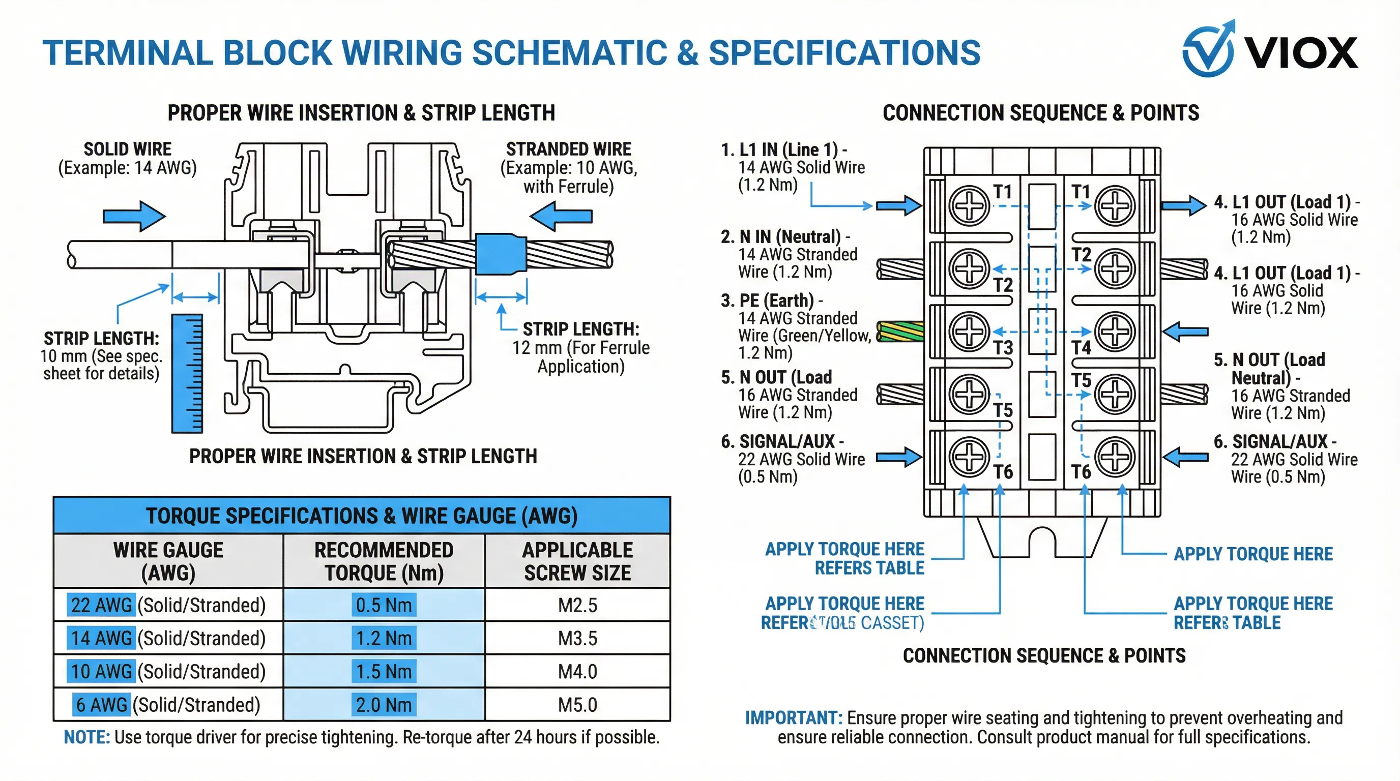
Torque Specifications:
- ဝက်အူအမျိုးအစား terminals: ဝါယာအရွယ်အစားပေါ်မူတည်၍ 0.5-2.5 Nm
- စပရိန်-ကေ့ခ်ျ terminals: ကြိုတင်သတ်မှတ်ထားသော စပရိန်အား (ပုံမှန်အားဖြင့် 15-30 N)
- ကြိုးပျက်စီးခြင်းမရှိဘဲ သင့်လျော်သောထိတွေ့မှုဖိအားအတွက် အရေးကြီးသည်။
တပ်ဆင်အကွာအဝေး:
- terminals များအကြား အလယ်ဗဟိုအကွာအဝေး
- အသုံးများသောအကွာအဝေးများ: 5mm, 5.08mm, 6.2mm, 8.2mm, 10mm, 12mm
- တပ်ဆင်သိပ်သည်းဆနှင့် ရှင်းလင်းရေးအကွာအဝေးကို ဆုံးဖြတ်သည်။
ပတ်ဝန်းကျင် အဆင့်သတ်မှတ်ချက်များ
အပူချိန်အကွာအဝေး:
- လည်ပတ်ခြင်း။: ပုံမှန်အားဖြင့် -40°C မှ +105°C သို့မဟုတ် +125°C
- သိုလှောင်ခြင်း: -40°C မှ +85°C
- ပစ္စည်းအပေါ်မူတည်သော ကန့်သတ်ချက်များ
IP အဆင့်သတ်မှတ်ချက် (ဝင်ရောက်မှုကာကွယ်ခြင်း):
- IP၂၀: ထိန်းချုပ်ဘောင်အတွင်းပိုင်းအသုံးပြုမှုအတွက် စံနှုန်း
- IP65/IP67: ထိတွေ့မှုရှိသော သို့မဟုတ် ဆေးကြောရသော အသုံးချမှုများအတွက်
- gaskets, seals သို့မဟုတ် အထူးအိမ်ရာများ လိုအပ်သည်။
Flame Retardancy:
- UL 94V-0: ၁၀ စက္ကန့်အတွင်း သူ့အလိုလိုငြိမ်းသည်။
- IEC 60695: အပူပေးဝါယာကြိုး စမ်းသပ်စံနှုန်းများ
- ပစ္စည်းအသိအမှတ်ပြုလက်မှတ်လိုအပ်ချက်များ
စံချိန်စံညွှန်းများ လိုက်နာခြင်း။
IEC ၆၀၉၄၇-၇-၁:
- terminal blocks များအတွက် အဓိကနိုင်ငံတကာစံနှုန်း
- အပူချိန်မြင့်တက်မှုကန့်သတ်ချက်များကို သတ်မှတ်သည် (အများဆုံး 45K)
- စက်ပိုင်းဆိုင်ရာခံနိုင်ရည်စမ်းသပ်ခြင်းကို သတ်မှတ်သည်။
UL 1059:
- မြောက်အမေရိကအစိတ်အပိုင်းစံနှုန်း
- တင်းကျပ်သောအပူချိန်မြင့်တက်မှုကန့်သတ်ချက်များ (အများဆုံး 30K)
- Use Group အမျိုးအစားခွဲခြားခြင်း (A, B, C, D)
DIN Rail စံနှုန်းများ:
- IEC 60715: ရထားလမ်းအတိုင်းအတာနှင့် တပ်ဆင်ခြင်း
- EN 50022: TH35 rail သတ်မှတ်ချက်များ
- စက်ပိုင်းဆိုင်ရာထိန်းသိမ်းအားလိုအပ်ချက်များ
ဇယား ၄: စံနှုန်းလိုက်နာမှုဇယား: IEC, UL, DIN
| စံအမျိုးအစား | IEC (နိုင်ငံတကာ) | UL / CSA (မြောက်အမေရိက) | DIN / EN (ဥရောပ) |
|---|---|---|---|
| Terminal Block (အထွေထွေ) | IEC 60947-7-1 (ပါဝါ) IEC 60947-7-2 (အကာအကွယ်မြေကြီး) |
UL 1059 CSA C၂၂။၂ No။ ၁၅၈ |
EN 60947-7-1 VDE 0611 |
| Mounting Rail | IEC 60715 | UL 508A (ကိုးကား) | EN 50022 (TH35) DIN 46277 |
| မီးလောင်လွယ်မှု / မီးဘေးကင်းရေး | IEC 60695-2 (အပူပေးဝါယာကြိုး) | UL 94 (V-0, V-1, V-2) | EN 45545-2 (ရထားလမ်း) DIN 5510-2 |
| ကာကွယ်မှုဒီဂရီ (IP) | IEC 60529 (IP Code) | NEMA 250 (အကာအကွယ်အမျိုးအစားများ) | EN 60529 DIN 40050 |
| တုန်ခါမှုနှင့် တုန်လှုပ်မှု | IEC 60068-2-6 (တုန်ခါမှု) IEC 60068-2-27 (တုန်လှုပ်မှု) |
UL 1059 (လုံခြုံမှုစမ်းသပ်ခြင်း) | EN 61373 (ရထားတွဲများ) |
| ရှင်းလင်းမှုနှင့် ယိုစိမ့်မှု | IEC 60664-1 | UL 840 | EN 60664-1 VDE 0110 |
နည်းပညာဆိုင်ရာ သတ်မှတ်ချက်များကို နားလည်ခြင်းသည် စျေးကွက်ရှာဖွေရေး ကြော်ငြာများထက် အမှန်တကယ် အသုံးပြုမှုလိုအပ်ချက်များအပေါ် အခြေခံ၍ သင့်လျော်သော terminal block ရွေးချယ်မှုကို လုပ်ဆောင်နိုင်စေပါသည်။ သင်၏ ပထဝီဝင်ဒေသနှင့် စက်မှုကဏ္ဍအတွက် သက်ဆိုင်ရာ စံနှုန်းများနှင့်အညီ အမြဲစစ်ဆေးပါ။.
အသုံးပြုမှုလိုအပ်ချက်များအတွက် အစိတ်အပိုင်းရွေးချယ်ခြင်း
ယေဘူယျ သတ်မှတ်ချက်များထက် အသုံးပြုမှုလိုအပ်ချက်များအပေါ် အခြေခံ၍ terminal block များကို ရွေးချယ်ခြင်းသည် အကောင်းဆုံး စွမ်းဆောင်ရည်၊ ယုံကြည်စိတ်ချရမှုနှင့် စုစုပေါင်း ပိုင်ဆိုင်မှုကုန်ကျစရိတ်ကို သေချာစေပါသည်။ အောက်ပါ ဆုံးဖြတ်ချက်မူဘောင်သည် အသုံးများသော စက်မှုလုပ်ငန်းဆိုင်ရာ အခြေအနေများကို ဖြေရှင်းပေးပါသည်။.
အသုံးပြုမှုအလိုက် ရွေးချယ်မှုစံနှုန်းများ
ထိန်းချုပ်ဘောင် ဝါယာကြိုး (အထွေထွေရည်ရွယ်ချက်):
- အိမ်ရာ: ဖန်မျှင်အားဖြည့်ထားသော Polyamide 6.6 (PA66)
- Clamping (ဗို့အားကို ထိန်းညှိပေးခြင်း): တုန်ခါမှုကိုခံနိုင်ရည်ရှိသော Spring-cage
- ဝါယာကြိုး အကွာအဝေး: 22-10 AWG (0.5-6 mm²)
- လက်ရှိအဆင့်သတ်မှတ်: 20-32A စဉ်ဆက်မပြတ်
- စံနှုန်းများ: IEC 60947-7-1, UL 1059 Group C
ပါဝါဖြန့်ဖြူးခြင်း (မြင့်မားသော လျှပ်စီးကြောင်း):
- အိမ်ရာ: အရွယ်အစား တည်ငြိမ်မှုအတွက် PBT
- Clamping (ဗို့အားကို ထိန်းညှိပေးခြင်း): မြင့်မားသော ညှပ်အားအတွက် Screw-type
- ဝါယာကြိုး အကွာအဝေး: 14-2/0 AWG (2.5-95 mm²)
- လက်ရှိအဆင့်သတ်မှတ်: 40-125A စဉ်ဆက်မပြတ်
- စံနှုန်းများ: ပတ်ဝန်းကျင်အပူချိန် >40°C အတွက် လျှော့ချထားသော IEC 60947-7-1
တုန်ခါမှုဖြစ်နိုင်သော ပတ်ဝန်းကျင်များ (သယ်ယူပို့ဆောင်ရေး၊ စက်ယန္တရား):
- အိမ်ရာ: သက်ရောက်မှုကို ခံနိုင်ရည်ရှိသော PA66
- Clamping (ဗို့အားကို ထိန်းညှိပေးခြင်း): အပြုသဘောဆောင်သော လော့ခ်စနစ်ပါရှိသော Spring-cage
- ပစ္စည်းများ: သံမဏိစပရိန်များ၊ သံချေးတက်ခြင်းကို ခံနိုင်ရည်ရှိသော သတ္တုပြား
- စမ်းသပ်ခြင်း။: IEC 60068-2-6 တုန်ခါမှု လိုက်နာမှု
စိုထိုင်းဆမြင့်မားသော သို့မဟုတ် တိုက်စားနိုင်သော ပတ်ဝန်းကျင်များ (ပင်လယ်ရေကြောင်း၊ ဓာတု):
- အိမ်ရာ: ဓာတုဗေဒကို ခံနိုင်ရည်ရှိသော PBT သို့မဟုတ် polycarbonate
- Clamping (ဗို့အားကို ထိန်းညှိပေးခြင်း): သံမဏိအစိတ်အပိုင်းများပါရှိသော Screw-type
- သတ္တုပြား: သံချေးတက်ခြင်းကို ကာကွယ်ရန် နီကယ် သို့မဟုတ် ငွေ
- IP အဆင့်သတ်မှတ်ချက်: ထိတွေ့နိုင်သော အသုံးပြုမှုများအတွက် အနည်းဆုံး IP65
အသုံးများသော အခြေအနေများအတွက် ဆုံးဖြတ်ချက်ဇယား
| လျှောက်လွှာ | ဦးစားပေးစံနှုန်းများ | အကြံပြုထားသော နည်းပညာ | အဓိက စံချိန်စံညွှန်းများ |
|---|---|---|---|
| အထွေထွေ ထိန်းချုပ်ဘောင် | တုန်ခါမှုကို ခံနိုင်ရည်ရှိခြင်း၊ ပြုပြင်ထိန်းသိမ်းမှု မလိုအပ်ခြင်း | Spring-cage | IEC 60947-7-1, UL 1059 Group C |
| မြင့်မားသော လျှပ်စီးကြောင်း ထောက်ပံ့ပေးသူ | ညှပ်အား၊ အပူစွမ်းအင် လျော့ပါးခြင်း | Screw-type | လျှော့ချထားသော IEC 60947-7-1 |
| အသံအတိုးအကျယ် မြင့်မားသော တပ်ဆင်မှု | တပ်ဆင်မှုအမြန်နှုန်း၊ သိပ်သည်းဆ | Push-in spring | IEC 60947-7-1, UL 1059 Group B/C |
| ကြမ်းတမ်းသော ပတ်ဝန်းကျင် | ဓာတုဗေဒကို ခံနိုင်ရည်ရှိခြင်း၊ သံချေးတက်ခြင်းကို ကာကွယ်ခြင်း | သံမဏိအစိတ်အပိုင်းများပါရှိသော Screw-type | IP65, IEC 60068-2-11 |
| ရောနှောထားသော ဝါယာကြိုး အမျိုးအစားများ | တစ်လောကလုံးလိုက်ဖက်မှု | Screw-type | IEC 60947-7-1, UL 1059 Group C |
ဝေဖန်ပိုင်းခြားစဉ်းစားမှုများ
စုစုပေါင်းပိုင်ဆိုင်မှုကုန်ကျစရိတ်:
- မူလအစိတ်အပိုင်း ကုန်ကျစရိတ်နှင့် တပ်ဆင်မှုလုပ်အား
- ပြုပြင်ထိန်းသိမ်းမှုလိုအပ်ချက်များနှင့် ရပ်ဆိုင်းချိန်
- ရေရှည်တည်တံ့ခိုင်မြဲမှုနှင့် အစားထိုးလဲလှယ်မှု ကြိမ်နှုန်း
စံချိန်စံညွှန်းများ လိုက်နာခြင်း။:
- ပထဝီဝင်ဆိုင်ရာ လိုအပ်ချက်များ (IEC vs. UL/NEC)
- စက်မှုလုပ်ငန်းဆိုင်ရာ သီးခြားအသိအမှတ်ပြုလက်မှတ်များ (ATEX, ပင်လယ်ရေကြောင်း, ရထားလမ်း)
- သုံးစွဲသူ သတ်မှတ်ချက် လိုက်နာမှု
Future-Proofing:
- အနာဂတ် တိုးချဲ့မှုအတွက် အပိုပစ္စည်း
- ရှိပြီးသားစနစ်များနှင့် လိုက်ဖက်ညီမှု
- Availability of replacement parts
အသုံးပြုမှုအပေါ် အခြေခံသော ရွေးချယ်မှုသည် terminal block စွမ်းဆောင်ရည်ကို အမှန်တကယ် လည်ပတ်မှုအခြေအနေများနှင့် ကိုက်ညီစေရန် ကတ်တလောက် သတ်မှတ်ချက်များကို ကျော်လွန်သွားပါသည်။ ဤချဉ်းကပ်မှုသည် လယ်ပြင်ပျက်ကွက်မှုများကို လျှော့ချပေးပြီး စုစုပေါင်း သက်တမ်းကုန်ကျစရိတ်များကို လျှော့ချပေးကာ သက်ဆိုင်ရာ စံနှုန်းများနှင့်အညီ လိုက်နာကြောင်း သေချာစေပါသည်။.
မကြာခဏမေးမေးခွန်းများ
1. What’s the difference between terminal block housing materials (PA66 vs PBT vs PC)?
PA66 (Polyamide 6.6) offers excellent mechanical strength and flexibility, making it ideal for general industrial applications. PBT (Polybutylene Terephthalate) provides superior dimensional stability and moisture resistance for precision applications. PC (Polycarbonate) delivers high impact strength and transparency for visual inspection requirements. Selection depends on environmental conditions and mechanical requirements.
2. How do I choose between screw, spring-cage, and push-in clamping mechanisms?
Screw-type terminals provide universal wire compatibility and field serviceability. Spring-cage terminals offer maintenance-free, vibration-resistant connections. Push-in terminals enable tool-less installation for rigid conductors. Choose based on installation speed, maintenance requirements, and environmental conditions.
3. What current rating should I select for my application?
Select a terminal block rated for at least 150% of your maximum expected continuous current. Apply derating for ambient temperatures above 40°C (typically 0.8% per °C). Consider both the terminal block rating and the wire’s ampacity.
4. How do IEC 60947-7-1 and UL 1059 standards differ?
IEC ၆၀၉၄၇-၇-၁ is the international standard with 45K maximum temperature rise. UL 1059 is the North American standard with stricter 30K temperature rise limits and Use Group classifications (A, B, C, D). Products may have dual ratings with different values for each standard.
5. What wire preparation is required for different terminal types?
Screw-type: Solid or stranded wires, strip length per manufacturer specs. Spring-cage: Solid, stranded, or fine-stranded with proper strip length. Push-in: Rigid conductors (solid or ferruled stranded), precise strip length critical. Always follow manufacturer specifications.
6. How do terminal blocks handle vibration and thermal cycling?
Quality terminal blocks use spring-loaded mechanisms that maintain constant pressure during vibration. Materials with compatible thermal expansion coefficients prevent stress concentration. Designs include positive locking features and corrosion-resistant components for harsh environments.
VIOX Terminal Block Solutions
VIOX Electric designs and manufactures terminal blocks engineered for industrial reliability and performance. Our product range combines material science expertise with precision manufacturing to deliver connection solutions that withstand demanding operating conditions.
VIOX Terminal Block Features:
- Material Engineering: Glass-reinforced PA66, moisture-resistant PBT, and impact-resistant polycarbonate housings
- Clamping Technologies: Screw-type, spring-cage, and push-in mechanisms for diverse application requirements
- စံချိန်စံညွှန်းများ လိုက်နာခြင်း။: Dual-rated products meeting IEC 60947-7-1 and UL 1059 standards with global approvals
- အပူပိုင်းစွမ်းဆောင်ရည်: Optimized designs for heat dissipation with derating guidance for elevated ambient temperatures
- တပ်ဆင်ခြင်း စွမ်းဆောင်ရည်: Tool-less and tool-assisted options balancing speed with reliability
Technical Support and Specification Assistance:
Our engineering team provides application-specific guidance for terminal block selection based on:
- လက်ရှိနှင့်ဗို့အားလိုအပ်ချက်များ
- Environmental conditions (temperature, humidity, chemical exposure)
- Vibration and mechanical stress factors
- Standards compliance needs (IEC, UL, ATEX, marine)
- Installation workflow optimization
Explore VIOX Terminal Block Products: https://viox.com/terminal-block
For technical specifications, application guidance, or custom solution inquiries, contact our engineering support team through the VIOX website or your local VIOX representative.
