
ဆိုလာပေါင်းစပ်သေတ္တာတစ်ခု အပူချိန်လွန်ကဲလာသောအခါ၊ နောက်ဆက်တွဲများသည် အဆင်မပြေမှုထက် များစွာကျော်လွန်သွားသည်—အပူပိုင်းဆိုင်ရာ ချို့ယွင်းမှုများသည် ဓာတ်အားအလင်းစနစ်များတွင် အဖြစ်အများဆုံးနှင့် အန္တရာယ်အရှိဆုံး ချို့ယွင်းမှုပုံစံများထဲမှ တစ်ခုဖြစ်သည်။ ဆိုလာပေါင်းစပ်သေတ္တာအတွင်း အပူချိန်လွန်ကဲခြင်းသည် အစိတ်အပိုင်းများ ယိုယွင်းပျက်စီးခြင်း၊ အနှောင့်အယှက်ဖြစ်စေသော ခရီးစဉ်များ၊ စနစ်ရပ်ဆိုင်းခြင်းနှင့် ပြင်းထန်သောအခြေအနေများတွင် လျှပ်စစ်မီးလောင်မှုများဖြစ်ပွားစေပြီး စက်ပစ္စည်းနှင့် ဝန်ထမ်းများ၏ ဘေးကင်းလုံခြုံမှုကို ခြိမ်းခြောက်နိုင်သည်။ PV စနစ်များကို သတ်မှတ်ပေးသော ဒီဇိုင်းအင်ဂျင်နီယာများနှင့် လျှပ်စစ်ကန်ထရိုက်တာများအတွက် အပူပိုင်းဆိုင်ရာ ချို့ယွင်းမှု၏ အရင်းခံအကြောင်းရင်းများကို နားလည်ခြင်းသည် ကုန်ကျစရိတ်ကြီးမြင့်သော လယ်ပြင်ချို့ယွင်းမှုများကို ကာကွယ်ရန်နှင့် ရေရှည်စနစ်၏ ယုံကြည်စိတ်ချရမှုကို သေချာစေရန်အတွက် မရှိမဖြစ်လိုအပ်ပါသည်။.
ဆိုလာပေါင်းစပ်သေတ္တာသည် အင်ဗာတာကို မပို့လွှတ်မီ အကွက်ဆားကစ်များစွာ စုစည်းရာ အရေးပါသော စုစည်းမှတ်အဖြစ် လုပ်ဆောင်သည်။ ဤ DC လျှပ်စီးကြောင်း၏ ပြင်းအား—မကြာခဏ အမ်ပီယာရာပေါင်းများစွာ—သည် အပူချိန်စီမံခန့်ခွဲမှုကို ညှိနှိုင်း၍မရနိုင်ပါ။ သို့သော် အပူချိန်လွန်ကဲသော ချို့ယွင်းမှုများသည် စက်မှုလုပ်ငန်းတစ်လျှောက်တွင် အသေးစားစီးပွားဖြစ် တပ်ဆင်မှုများမှသည် အသုံးဝင်သော ဆိုလာလယ်ယာများအထိ ပျံ့နှံ့နေဆဲဖြစ်သည်။ အရင်းခံအကြောင်းရင်းများတွင် အရွယ်အစားသေးငယ်သော အစိတ်အပိုင်းများ၊ မလုံလောက်သော အပူပိုင်းဆိုင်ရာ ဒီဇိုင်း၊ ညံ့ဖျင်းသော တပ်ဆင်မှုအလေ့အကျင့်များနှင့် အချိန်ကြာလာသည်နှင့်အမျှ ပေါင်းစပ်ထားသော ပတ်ဝန်းကျင်ဆိုင်ရာ ဖိစီးမှုများ ပါဝင်လေ့ရှိသည်။.
ဤအင်ဂျင်နီယာလမ်းညွှန်သည် ဆိုလာပေါင်းစပ်သေတ္တာ အပူချိန်လွန်ကဲခြင်း၏ အဓိက အရင်းခံအကြောင်းရင်းငါးခုကို စစ်ဆေးပြီး အပူပိုင်းဆိုင်ရာ သိပ္ပံ၊ လျှပ်စစ်စံနှုန်းများနှင့် လယ်ပြင်တွင် သက်သေပြထားသော အကောင်းဆုံးအလေ့အကျင့်များအပေါ် အခြေခံထားသော ဒီဇိုင်းအဆင့်ဖြေရှင်းချက်များကို ပေးပါသည်။.
ပုံမှန်နှင့် မူမမှန်သော အပူချိန်မြင့်တက်မှုကို နားလည်ခြင်း
အပူချိန်လွန်ကဲခြင်းကို မစစ်ဆေးမီ အင်ဂျင်နီယာများသည် ဆိုလာပေါင်းစပ်သေတ္တာ အစိတ်အပိုင်းများတွင် လက်ခံနိုင်သော အပူချိန်မြင့်တက်မှုအတွက် အခြေခံမျှော်လင့်ချက်များကို ထူထောင်ရပါမည်။ လျှပ်စစ်ချိတ်ဆက်မှုအားလုံးသည် I²R ဆုံးရှုံးမှုများကြောင့် အပူကိုထုတ်ပေးသည်—ပျံ့နှံ့သွားသော ပါဝါသည် ခုခံမှုနှင့် လျှပ်စီးကြောင်း၏ စတုရန်းနှင့် အချိုးကျသည်။ မေးခွန်းမှာ အပူထုတ်ပေးမလား မဟုတ်ဘဲ လျှပ်စစ်စံနှုန်းများဖြင့် သတ်မှတ်ထားသော ဘေးကင်းလုံခြုံသော ကန့်သတ်ချက်များအတွင်း ရှိနေသေးသလားဟူ၍ ဖြစ်သည်။.
IEC 60947-1 အရ လျှပ်စစ် terminal များအတွက် ခွင့်ပြုနိုင်သော အပူချိန်မြင့်တက်မှုသည် ကိုးကားထားသော ပတ်ဝန်းကျင်အပူချိန်ထက် 70 K (70°C) ဖြစ်သည်။ ဆိုလာတပ်ဆင်မှုများတွင် အများအားဖြင့် 40°C ပတ်ဝန်းကျင်အခြေခံကို ယူဆပါက ၎င်းသည် အများဆုံးခွင့်ပြုနိုင်သော terminal အပူချိန် 110°C ကို ရရှိစေသည်။ တပ်ဆင်မှုအတွင်းရှိ busbar များအတွက် IEC 61439-1 သည် ပိုမိုမြင့်မားသော အပူချိန်များကို ခွင့်ပြုသည်- ဗလာကြေးနီ busbar များသည် 140°C အထိ လည်ပတ်နိုင်ပြီး အပူချိန်မြင့်တက်မှုကန့်သတ်ချက်သည် ပတ်ဝန်းကျင်ထက် ကြေးနီအတွက် 70°C နှင့် အလူမီနီယမ် busbar များအတွက် 55°C ဖြစ်သည်။.
UL စံနှုန်းများသည် အစိတ်အပိုင်းဗဟိုပြုချဉ်းကပ်မှုကို ခံယူသည်။ UL 489 (ဆားကစ်ဘရိတ်ကာများ) အောက်တွင် စံနှုန်းသတ်မှတ်ထားသော အဆုံးသတ်များသည် 40°C ပတ်ဝန်းကျင်ထက် 50°C အပူချိန်မြင့်တက်မှုကို ခွင့်ပြုပြီး အများဆုံးလည်ပတ်အပူချိန် 90°C ကို ရရှိစေသည်။ အရေးပါသော အချက်မှာ အနှောင့်အယှက်ဖြစ်စေသော ခရီးစဉ်နှင့် အစိတ်အပိုင်းများ ယိုယွင်းပျက်စီးခြင်း—terminal အပူချိန်များသည် ဤဒီဇိုင်းကန့်သတ်ချက်များထက် ကျော်လွန်သောအခါ အပူကာကွယ်ရေးကိရိယာများသည် အချိန်မတိုင်မီ ခရီးထွက်နိုင်ပြီး လျှပ်ကာသည် လျင်မြန်စွာ ယိုယွင်းပျက်စီးလာသည်။.
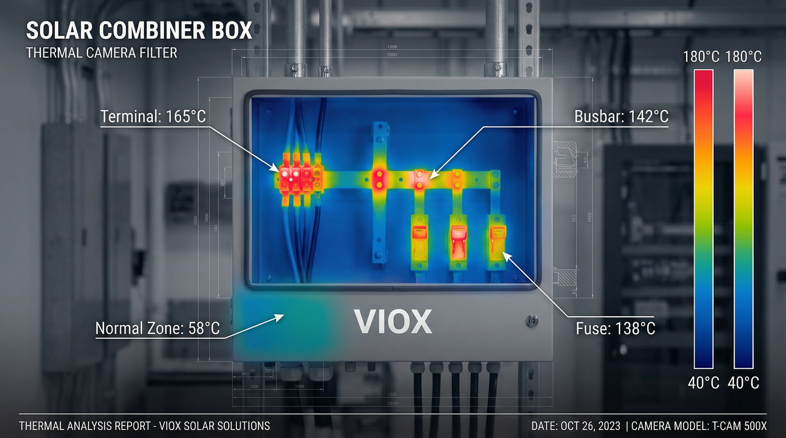
မူမမှန်သော အပူချိန်မြင့်တက်မှုသည် ဤအချက်များထက် သိသိသာသာကျော်လွန်သော ဒေသတွင်း အပူပိုင်းနေရာများအဖြစ် ထင်ရှားသည်။ ချို့ယွင်းနေသော တပ်ဆင်မှုများ၏ အပူပိုင်းပုံရိပ်ဖော်လေ့လာမှုများအရ terminal ချိတ်ဆက်မှုများနှင့် busbar အဆစ်များတွင် 120°C မှ 180°C ကျော်အထိ အပူပိုင်းနေရာများကို ပြသထားသည်—အပူချိန်များသည် ချို့ယွင်းဇုန်ထဲသို့ ကောင်းစွာရောက်ရှိနေပြီဖြစ်သည်။ ဤမြင့်မားသောအပူချိန်များတွင် ကြေးနီသည် လျင်မြန်စွာ အောက်ဆီဂျင်ဓာတ်တိုးလာပြီး ချိတ်ဆက်မှုခုခံမှုသည် တိုးပွားလာကာ အပူပိုင်းဆိုင်ရာ ထွက်ပြေးမှုဖြစ်နိုင်ခြေရှိသည်။.
အရင်းခံအကြောင်းရင်း #1- အရွယ်အစားသေးငယ်သော အစိတ်အပိုင်းများ
ဆိုလာပေါင်းစပ်သေတ္တာ အပူချိန်လွန်ကဲခြင်း၏ အခြေခံအကျဆုံးအကြောင်းရင်းမှာ အမှန်တကယ်လည်ပတ်မှုအခြေအနေများအတွက် လုံလောက်သော လျှပ်စီးကြောင်းသယ်ဆောင်နိုင်စွမ်းမရှိသော အစိတ်အပိုင်းများကို ရွေးချယ်ခြင်းဖြစ်သည်။ အရွယ်အစားသေးငယ်ခြင်းသည် အဆင့်များစွာတွင် ဖြစ်ပွားသည်- terminal များ၊ busbar များ၊ ဖျူးများနှင့် ဆားကစ်ဘရိတ်ကာများ—၎င်းတို့ထဲမှ တစ်ခုခုသည် အပူပိုင်းဆိုင်ရာ လည်ပင်းညှစ်ဖြစ်လာနိုင်သည်။.
Busbar ကန့်လန့်ဖြတ်ဧရိယာ- Busbar အရွယ်အစားကို လျှပ်စီးကြောင်းသိပ်သည်းဆမူများဖြင့် အုပ်ချုပ်သည်။ ကြေးနီ busbar များအတွက် အင်ဂျင်နီယာများသည် ပုံမှန်အားဖြင့် 1.2 မှ 1.6 A/mm² ၏ ရှေးရိုးဆန်သော လျှပ်စီးကြောင်းသိပ်သည်းဆကို အသုံးပြုကြသည်။ 500 A စဉ်ဆက်မပြတ်လျှပ်စီးကြောင်းသည် ခန့်မှန်းခြေအားဖြင့် အနည်းဆုံး 417 mm² ကန့်လန့်ဖြတ်ပိုင်း (500 A ÷ 1.2 A/mm²) လိုအပ်ပြီး ပုံမှန်အားဖြင့် 40mm × 10mm (400 mm²) သို့မဟုတ် 50mm × 10mm (500 mm²) busbar ဖြင့် ကျေနပ်သည်။ အလူမီနီယမ် busbar များသည် လျှပ်ကူးနိုင်စွမ်းနည်းပါးသောကြောင့် 0.8 A/mm² ဝန်းကျင်တွင် လျှပ်စီးကြောင်းသိပ်သည်းဆနည်းပြီး သက်ဆိုင်ရာအရွယ်အစားကြီးမားသော ကန့်လန့်ဖြတ်ပိုင်းများ လိုအပ်သည်။ ကျဉ်းမြောင်းသော busbar သည် ခုခံမှုပိုမိုမြင့်မားရုံသာမက အပူပျံ့နှံ့မှုအတွက် မျက်နှာပြင်ဧရိယာကိုလည်း လျှော့ချပေးသည်—ပေါင်းစပ်အပူပိုင်းဆိုင်ရာ ပြစ်ဒဏ်ဖြစ်သည်။.
busbar ၏ ခုခံမှုသည် ဖော်မြူလာ R = (ρ × L) / A ကို လိုက်နာပြီး ρ သည် ခုခံနိုင်စွမ်း (20°C တွင် ကြေးနီအတွက် 1.724 × 10⁻⁸ Ω·m)၊ L သည် အရှည်နှင့် A သည် ကန့်လန့်ဖြတ်ဧရိယာဖြစ်သည်။ ပါဝါဆုံးရှုံးမှုမှာ P = I² × R ဖြစ်သည်။ သေးငယ်သော အရွယ်အစားပင်လျှင် ခုခံမှုကို နှစ်ဆတိုးစေပြီး လျှပ်စီးကြောင်းတိုးလာမှုနှင့် ပေါင်းစပ်လိုက်သောအခါ အပူထုတ်လုပ်မှုကို လေးဆတိုးစေသည်။.
Terminal နှင့် ချိတ်ဆက်မှု အဆင့်သတ်မှတ်ချက်များ- Terminal block များနှင့် lug ချိတ်ဆက်မှုများကို သင့်လျော်သော ဘေးကင်းလုံခြုံရေးအနားသတ်များဖြင့် အမြင့်ဆုံးအကွက်လျှပ်စီးကြောင်းအတွက် အဆင့်သတ်မှတ်ရပါမည်။ ဆိုလာအသုံးချပရိုဂရမ်များတွင် NEC သည် စဉ်ဆက်မပြတ်လျှပ်စီးကြောင်း အဆင့်သတ်မှတ်ချက်များတွင် 125% ဘေးကင်းလုံခြုံရေးအချက်ကို လိုအပ်သည်။ 12 A ကို စဉ်ဆက်မပြတ်သယ်ဆောင်သည့် အကွက်တစ်ခုသည် အနည်းဆုံး 15 A အတွက် အဆင့်သတ်မှတ်ထားသော terminal များ လိုအပ်သည်။ ဤလျှော့ချမှုကို အသုံးမချနိုင်ခြင်းသည် terminal များသည် ၎င်းတို့၏ အပူပိုင်းဆိုင်ရာ ဒီဇိုင်းကန့်သတ်ချက်များထက် ကျော်လွန်လည်ပတ်စေပြီး ယိုယွင်းပျက်စီးမှုကို အရှိန်မြှင့်စေသည်။.
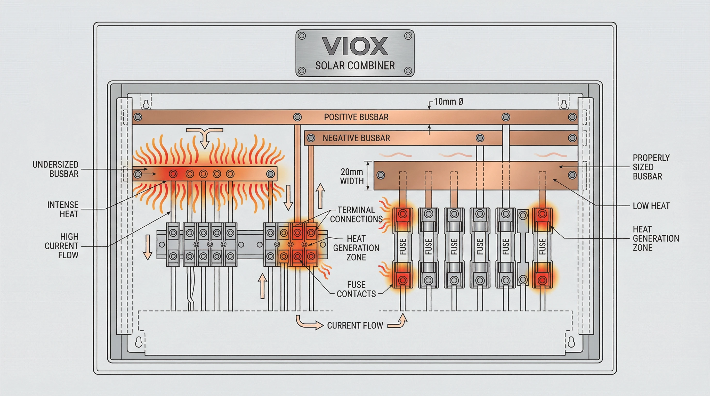
ဖျူးနှင့် ဘရိတ်ကာ အရွယ်အစား- အရွယ်အစားသေးငယ်သော ဖျူးများသည် အပူပိုင်းဆိုင်ရာ ယိုယွင်းပျက်စီးခြင်းနှင့် အချိန်မတိုင်မီ ပွင့်လင်းလာခြင်းကို ခံစားရသည်။ ဖျူးများကို 25°C ပတ်ဝန်းကျင်တွင် အဆင့်သတ်မှတ်ထားသောကြောင့် မြင့်မားသော ပေါင်းစပ်သေတ္တာအတွင်းပိုင်း အပူချိန်များ (မကြာခဏ 60-70°C) တွင် လည်ပတ်ရန် လျှော့ချရန် လိုအပ်သည်။ 60°C တွင် 0.84 လျှော့ချသည့်အချက်ပါရှိသော ဖျူးတစ်ခုကို လျော်ကြေးပေးရန်အတွက် အဆင့်မြှင့်တင်ရမည်—60°C တွင် 12 A ဆားကစ်ကို ကာကွယ်ရန်အတွက် အမည်ခံ 15 A ဖျူး (12 A ÷ 0.84 ≈ 14.3 A) လိုအပ်သည်။ အလားတူပင် 40°C တွင် ချိန်ညှိထားသော ဆားကစ်ဘရိတ်ကာများသည် အပူချိန်မြင့်မားလာသောအခါ စွမ်းရည်ဆုံးရှုံးသည်; 100 A ဘရိတ်ကာသည် 60°C အတွင်းပိုင်းပတ်ဝန်းကျင်တွင် 80-85 A ကိုသာ ကိုင်တွယ်နိုင်သည်။.
အရင်းခံအကြောင်းရင်း #2- ညံ့ဖျင်းသော ချိတ်ဆက်မှုအရည်အသွေး
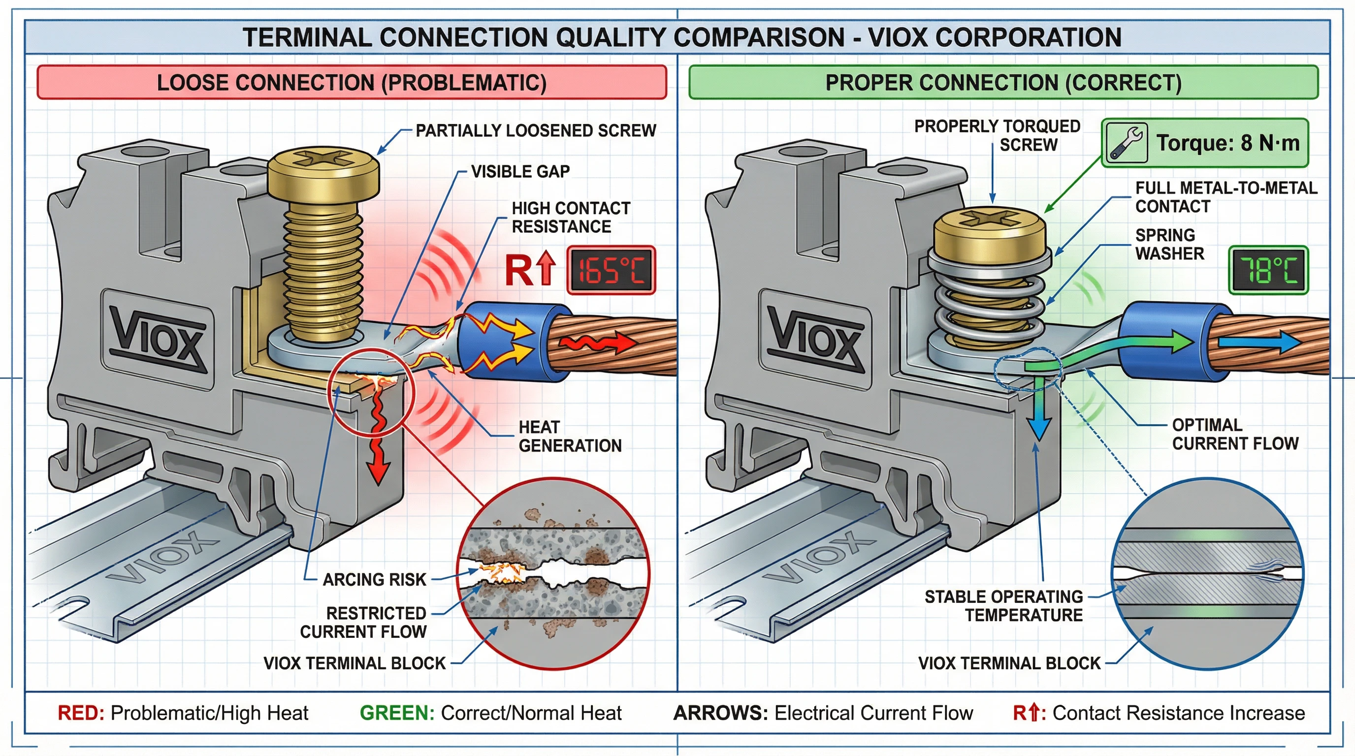
လျှပ်စစ်ချိတ်ဆက်မှုများတွင် အဆက်အသွယ်ခုခံမှုသည် ဆိုလာပေါင်းစပ်သေတ္တာများတွင် ဒေသတွင်း အပူချိန်လွန်ကဲခြင်း၏ အဖြစ်အများဆုံးအကြောင်းရင်းဖြစ်သည်။ မည်သည့်ချိတ်ဆက်မှုအမှတ်တွင်မဆို အပူအဖြစ် ပျံ့နှံ့သွားသော ပါဝါသည် P = I²R ဖြစ်သည်—ဆိုလိုသည်မှာ အဆက်အသွယ်ခုခံမှုတွင် အနည်းငယ်တိုးလာခြင်းပင်လျှင် မမျှတသော အပူကို ထုတ်ပေးသည်။ 50 A သယ်ဆောင်သည့် 10 mΩ ခုခံမှုရှိသော ချိတ်ဆက်မှုတစ်ခုသည် 25 W (50² × 0.01) ကို ပျံ့နှံ့စေပြီး တစ်ခုတည်းသော အဆစ်အမှတ်တွင် အာရုံစူးစိုက်ထားသည်။.
ချောင်နေသော ချိတ်ဆက်မှုများနှင့် အပူပိုင်းဆိုင်ရာ စက်ဝန်း- ကောင်းစွာတင်းကျပ်ထားခြင်းမရှိသော terminal ဝက်အူများသည် အဖြစ်အများဆုံး တပ်ဆင်မှုချို့ယွင်းချက်ဖြစ်သည်။ Terminal များကို ထုတ်လုပ်သူမှ သတ်မှတ်ထားသော torque တန်ဖိုးများအထိ တင်းကျပ်ရမည်—သေးငယ်သော terminal များအတွက် ပုံမှန်အားဖြင့် 3-5 N·m၊ ကြီးမားသော busbar များအတွက် 10-15 N·m အထိဖြစ်သည်။ အောက်ပိုင်းတင်းကျပ်ခြင်းသည် မြင့်မားသောခုခံမှုရှိသော ညံ့ဖျင်းသော သတ္တုနှင့်သတ္တုထိတွေ့မှုကို ဖန်တီးပေးသည်; အလွန်အကျွံတင်းကျပ်ခြင်းသည် ချည်မျှင်များကို ပျက်စီးစေပြီး ထိတွေ့မျက်နှာပြင်များကို ပုံပျက်စေကာ ချိတ်ဆက်မှုအရည်အသွေးကိုလည်း ယိုယွင်းစေနိုင်သည်။.
အပူပိုင်းဆိုင်ရာ စက်ဝန်းသည် အချိန်ကြာလာသည်နှင့်အမျှ ချောင်နေသော ချိတ်ဆက်မှုများကို ပိုမိုဆိုးရွားစေသည်။ ပေါင်းစပ်သေတ္တာသည် အထွတ်အထိပ် ဆိုလာနာရီများအတွင်း အပူချိန်တက်လာပြီး ညဘက်တွင် အေးသွားသောအခါ ကြေးနီလျှပ်ကူးပစ္စည်းများနှင့် သံမဏိ terminal ဟာ့ဒ်ဝဲများသည် မတူညီသောနှုန်းများဖြင့် ချဲ့ထွင်ပြီး ကျုံ့သွားသည် (အပူချဲ့ထွင်မှု ကိန်းဂဏန်းမကိုက်ညီမှု)။ ဤနေ့စဉ်စက်ဝန်းသည် စက်ပိုင်းဆိုင်ရာ ချိတ်ဆက်မှုများကို တဖြည်းဖြည်း ချောင်လာစေပြီး အဆက်အသွယ်ခုခံမှုကို တိုးမြင့်စေကာ အပူပိုင်းဆိုင်ရာ ယိုယွင်းပျက်စီးမှုကို အရှိန်မြှင့်စေသည်—အပူပိုင်းဆိုင်ရာ ထွက်ပြေးမှုဆီသို့ ဦးတည်သည့် အပြုသဘောဆောင်သော တုံ့ပြန်ချက်ကွင်းဆက်တစ်ခုဖြစ်သည်။.
သံချေးတက်ခြင်းနှင့် မျက်နှာပြင် အောက်ဆီဂျင်ဓာတ်တိုးခြင်း- အစိုဓာတ်၊ ဆားငန်လေ (ကမ်းရိုးတန်းတပ်ဆင်မှုများ) သို့မဟုတ် စက်မှုညစ်ညမ်းမှုများနှင့် ထိတွေ့ထားသော terminal မျက်နှာပြင်များသည် အောက်ဆိုက်အလွှာများနှင့် သံချေးတက်သည့် ထုတ်ကုန်များကို တီထွင်ထုတ်လုပ်ပြီး အဆက်အသွယ်ခုခံမှုကို သိသိသာသာ တိုးမြင့်စေသည်။ ကြေးနီအောက်ဆိုက်သည် သန့်စင်သော ကြေးနီထက် ခုခံနိုင်စွမ်း သိသိသာသာ မြင့်မားသည်။ ကောင်းစွာပြုလုပ်ထားခြင်းမရှိသော ချိတ်ဆက်မှုများ—မလုံလောက်သော ဝါယာကြိုးခွာခြင်း၊ ပျက်စီးနေသော ကြိုးများ သို့မဟုတ် ညံ့ဖျင်းစွာ ချုံ့ထားသော lug များ—သည် အောက်ဆီဂျင်ဓာတ်တိုးခြင်းကို အရှိန်မြှင့်ပေးသည့် အဏုကြည့်လေဟာနယ်များကို ဖန်တီးပေးသည်။.
MC4 ချိတ်ဆက်ကိရိယာ ယိုယွင်းပျက်စီးခြင်းကို အပူအရင်းအမြစ်အဖြစ် တဖြည်းဖြည်း အသိအမှတ်ပြုလာကြသည်။ ခရမ်းလွန်ရောင်ခြည်ထိတွေ့မှုသည် ပိုလီမာအိမ်ရာကို ယိုယွင်းစေပြီး အတွင်းရှိ နွေဦးအဆက်အသွယ်များသည် နှစ်ပေါင်းများစွာ အပူပိုင်းဆိုင်ရာ စက်ဝန်းအတွင်း တင်းအားဆုံးရှုံးကာ PV အကွက်ထည့်သွင်းမှုချိတ်ဆက်မှုများတွင် ခုခံမှုကို တိုးမြင့်စေသည်။.
အရင်းခံအကြောင်းရင်း #3- မလုံလောက်သော အပူပိုင်းဆိုင်ရာ ဒီဇိုင်း
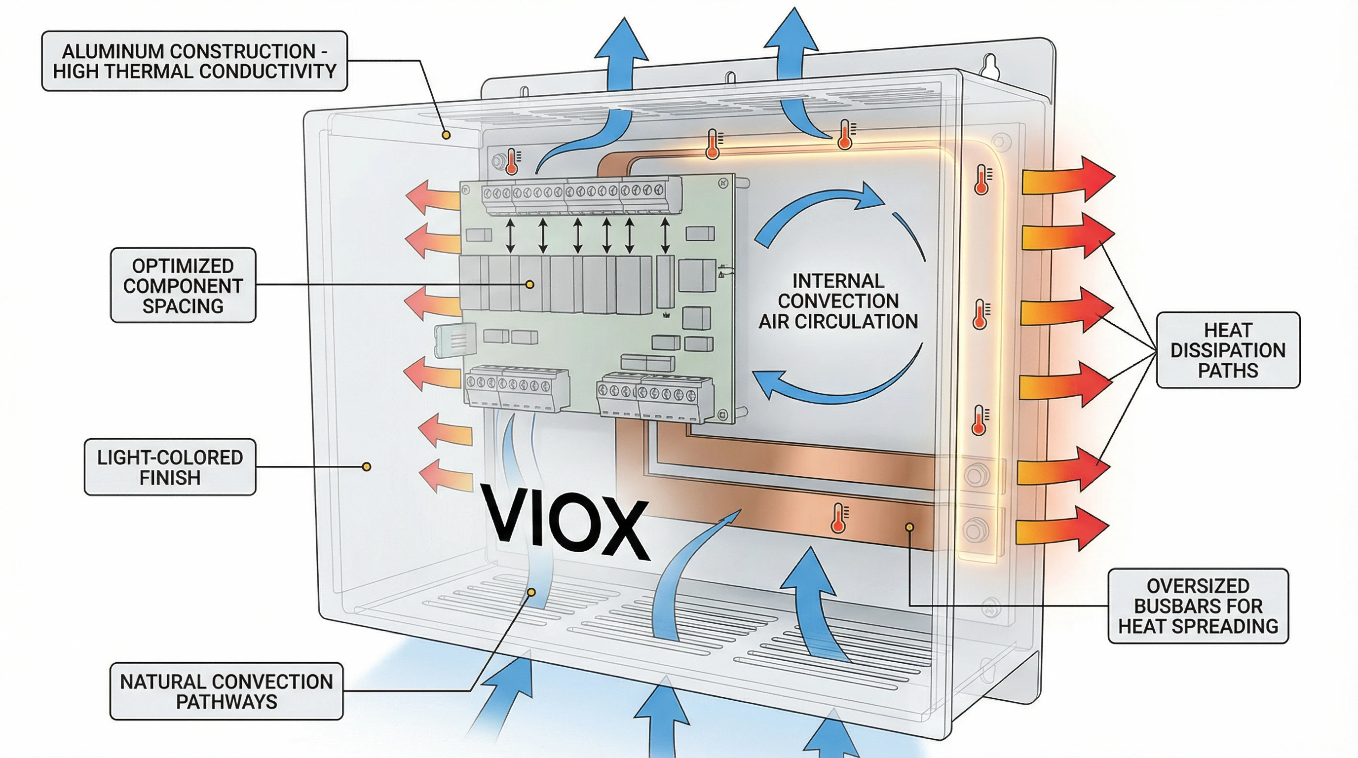
ပေါင်းစပ်သေတ္တာအကာသည် စုပုံနေသော အပူဝန်ကို မပျံ့နှံ့နိုင်ပါက ကောင်းစွာအရွယ်အစားရှိသော အစိတ်အပိုင်းများပင်လျှင် အပူချိန်လွန်ကဲလာမည်ဖြစ်သည်။ အပူပိုင်းဆိုင်ရာ ဒီဇိုင်းတွင် အကာအကွယ်ဂျီသြမေတြီ၊ လေဝင်လေထွက်ဗျူဟာ၊ အစိတ်အပိုင်းအကွာအဝေးနှင့် အပူလွှဲပြောင်းလမ်းကြောင်းများ ပါဝင်ပြီး ၎င်းတို့အားလုံးကို ကုန်ကျစရိတ်သက်သာသော ဒီဇိုင်းများတွင် မကြာခဏ လျစ်လျူရှုထားကြသည်။.
မလုံလောက်သော လေဝင်လေထွက်နှင့် လေစီးဆင်းမှု- ဆိုလာပေါင်းစပ်သေတ္တာအများစုသည် ရာသီဥတုနှင့် ဖုန်မှုန့်များဝင်ရောက်ခြင်းမှ ကာကွယ်ရန်အတွက် တံဆိပ်ခတ်ထားသော NEMA 4 သို့မဟုတ် IP65 အကာများကို အသုံးပြုကြသည်။ ဤတံဆိပ်ခတ်ခြင်းသည် အအေးခံစက်ယန္တရားအဖြစ် သဘာဝအတိုင်း လေဝင်လေထွက်ကို ဖယ်ရှားပေးပြီး အပူကိုအတွင်း၌ ပိတ်မိစေသည်။ အတွင်းပိုင်းအပူချိန်သည် ပြင်ပပတ်ဝန်းကျင်အပူချိန်၊ အစိတ်အပိုင်းများမှ ကိုယ်တိုင်အပူပေးခြင်းနှင့် အကာအကွယ်မှ စုပ်ယူထားသော နေရောင်ခြည်တို့၏ ပေါင်းလဒ်ဖြစ်လာသည်-
T_internal = T_ambient + ΔT_components + ΔT_solar
လေဝင်လေထွက်မရှိပါက ပြင်ပပတ်ဝန်းကျင်သည် 35-40°C သာရှိလျှင်ပင် အတွင်းပိုင်းအပူချိန်သည် နေရောင်အပြည့်အဝတွင် 70-80°C ထက် အလွယ်တကူ ကျော်လွန်နိုင်သည်။ အပူပျံ့နှံ့မှုသည် အကာအကွယ်နံရံများမှတဆင့် လျှပ်ကူးခြင်းနှင့် ပြင်ပမျက်နှာပြင်မှ ဓာတ်ရောင်ခြည်အပေါ်တွင်သာ မူတည်သည်။ အပူချိန်မြင့်တက်မှု (ΔT) ကို အပူဝန်သိပ်သည်းဆ (W/m²) နှင့် အကာအကွယ်မျက်နှာပြင်ဧရိယာဖြင့် ဆုံးဖြတ်သည်—တူညီသော အစိတ်အပိုင်းဝန်ပါရှိသော သေးငယ်သော အကာအကွယ်သည် အပူချိန်မြင့်တက်မှုကို ပိုမိုခံစားရသည်။.
အစိတ်အပိုင်း အကွာအဝေးနှင့် အပြင်အဆင်- အတွင်းပိုင်း အစိတ်အပိုင်းစီစဉ်မှုသည် အပူပျံ့နှံ့မှုကို အရေးပါစွာ သက်ရောက်မှုရှိသည်။ ထပ်နေသော busbar များ သို့မဟုတ် တင်းကျပ်စွာ စုစည်းထားသော ဖျူးကိုင်ဆောင်သူများသည် လေစီးဆင်းမှုကို ကန့်သတ်သည် (တံဆိပ်ခတ်ထားသော အကာများတွင်ပင် အတွင်းပိုင်း လေစီးကြောင်းများ ဖြစ်ပေါ်သည်) နှင့် ဒေသတွင်း အပူပိုင်းနေရာများကို ဖန်တီးပေးသည်။ အပူထုတ်ပေးသည့် အစိတ်အပိုင်းတစ်ခုစီ—ဖျူး၊ terminal block၊ busbar အဆစ်—သည် အပူကို တစ်နေရာတည်းတွင် အာရုံစူးစိုက်မည့်အစား ပျံ့နှံ့ပြီး ပျံ့နှံ့သွားစေရန်အတွက် လုံလောက်သော နေရာလွတ်လိုအပ်သည်။.
အကာအကွယ်ပစ္စည်းနှင့် အပူကူးနိုင်စွမ်း- သတ္တုအကာများ (သံမဏိ၊ အလူမီနီယမ်) သည် ဖိုက်ဘာမှန် သို့မဟုတ် ပိုလီကာဘွန်နိတ်အကာများထက် အပူကို ပိုမိုကောင်းမွန်စွာ ကူးပြောင်းပေးသည်။ အလူမီနီယမ်သည် အထူးသဖြင့် မြင့်မားသော အပူကူးနိုင်စွမ်း (~205 W/m·K) ရှိပြီး အပူစုပ်ခွက်အဖြစ် ထိရောက်စွာ လုပ်ဆောင်သည်။ ဆေးသုတ်ထားသော သို့မဟုတ် အပေါ်ယံလွှာပါရှိသော မျက်နှာပြင်များသည် ဓာတ်ရောင်ခြည်ဂုဏ်သတ္တိများကို ပြောင်းလဲစေသည်; အဖြူရောင် သို့မဟုတ် အလင်းမီးခိုးရောင် အချောထည်များသည် နေရောင်ခြည်ကို ပိုမိုရောင်ပြန်ဟပ်ပြီး အပူပျံ့နှံ့မှုကို တိုးတက်စေသည်။.
ပတ်ဝန်းကျင် အပူချိန် လျှော့ချခြင်း- ဒီဇိုင်းအင်ဂျင်နီယာများသည် လက်တွေ့ကျသော အတွင်းပိုင်းလည်ပတ်မှုပတ်ဝန်းကျင်အတွက် သင့်လျော်သော လျှော့ချမှုကို အသုံးချရန် မကြာခဏ ပျက်ကွက်ကြသည်။ အကယ်၍ အစိတ်အပိုင်းများကို 25°C ဓာတ်ခွဲခန်းအခြေအနေများအပေါ် အခြေခံ၍ ရွေးချယ်ထားသော်လည်း 70°C အတွင်းပိုင်းအပူချိန်သို့ ရောက်ရှိသည့် အကာတစ်ခုတွင် တပ်ဆင်ထားပါက ၎င်းတို့သည် ၎င်းတို့၏ အပူပိုင်းဆိုင်ရာ အိတ်ပြင်ပတွင် များစွာလည်ပတ်ကြသည်။ ဖျူးများ၊, ဆားကစ်မိျနှင့် terminal လုပ်ကွက်များ အားလုံးသည် ထုတ်လုပ်သူ၏ ဒေတာစာရွက်များမှ အပူချိန်-တိကျသော လျှော့ချသည့်မျဉ်းကွေးများ လိုအပ်သည်။.
အရင်းခံအကြောင်းရင်း #4- ပတ်ဝန်းကျင်ဆိုင်ရာ အချက်များ
ဆိုလာပေါင်းစပ်သေတ္တာများသည် ပြင်ပအခြေအနေများသည် လျှပ်စစ်အစိတ်အပိုင်းများမှ ထုတ်ပေးသော အပူထက် များစွာကျော်လွန်သော အပူပိုင်းဆိုင်ရာ ဖိစီးမှုများကို သက်ရောက်စေသည့် ကြမ်းတမ်းသော ပြင်ပပတ်ဝန်းကျင်တွင် လည်ပတ်သည်။.
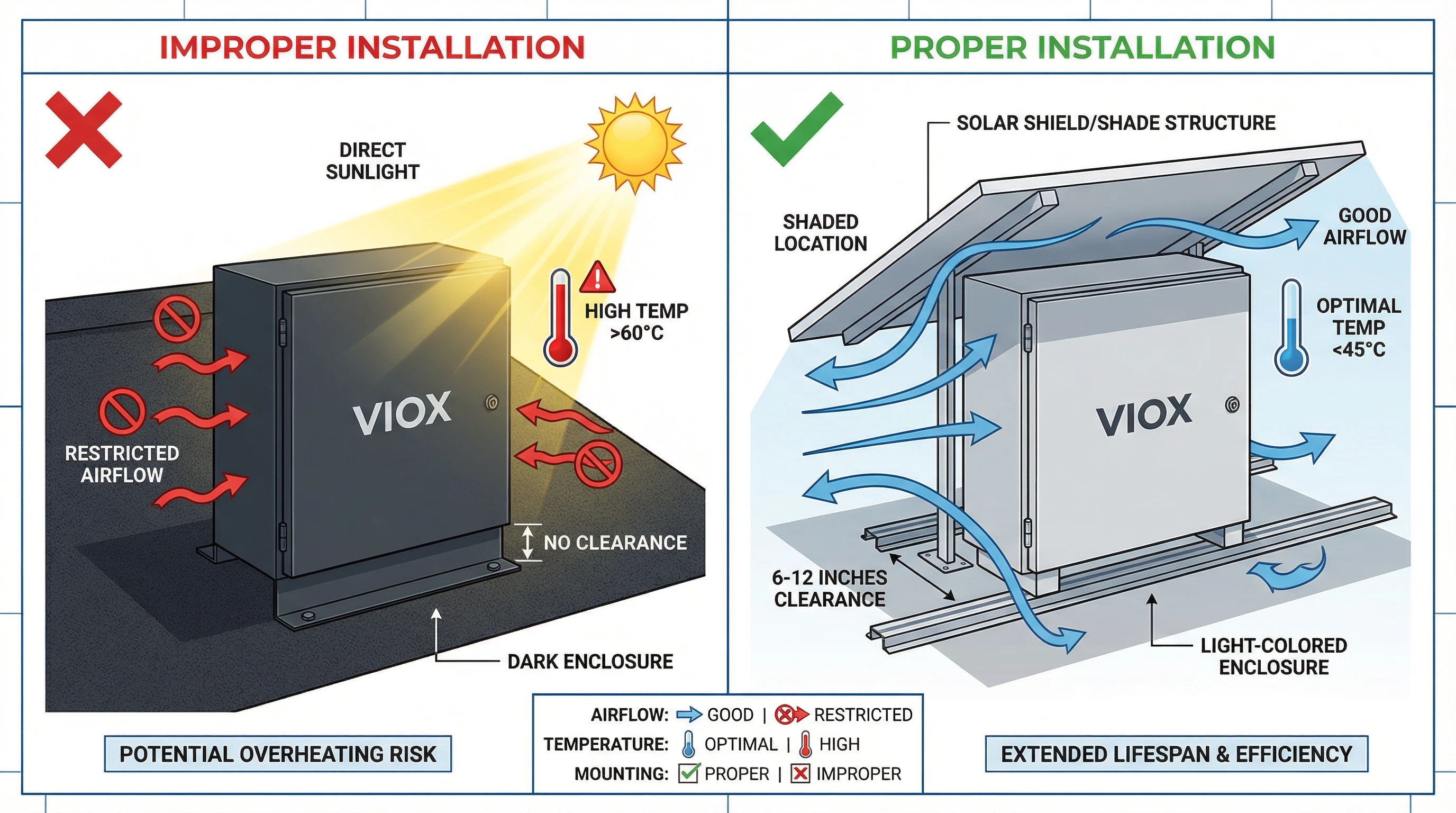
တိုက်ရိုက် နေရောင်ခြည်- တိုက်ရိုက်နေရောင်အောက်ရှိ အမှောင်ရောင်အကာတစ်ခုသည် 97 W/ft² (ဒေသများစွာတွင် အထွတ်အထိပ်နေရောင်ခြည်) ကို စုပ်ယူနိုင်ပြီး အတွင်းပိုင်းအပူချိန်သို့ သိသာထင်ရှားသော အပူဝန်ကို ထည့်နိုင်သည်။ အရောင်သည် စုပ်ယူမှုကို သိသိသာသာ သက်ရောက်မှုရှိသည်- အနက်ရောင်အကာတစ်ခုသည် တူညီသောအခြေအနေများအောက်တွင် အဖြူရောင်အကာတစ်ခုထက် 40-50°C ပိုမိုမြင့်မားသော မျက်နှာပြင်အပူချိန်သို့ ရောက်ရှိနိုင်သည်။ ဤနေရောင်ခြည်အပူရရှိမှုသည် အတွင်းပိုင်းအစိတ်အပိုင်းများသို့ တိုက်ရိုက်လွှဲပြောင်းပေးပြီး ထိရောက်သောပတ်ဝန်းကျင်အပူချိန်ကို မြှင့်တင်ပေးကာ အပူပျံ့နှံ့မှုအတွက် ရရှိနိုင်သော အပူချိန်ကွာခြားမှုကို လျှော့ချပေးသည်။.
Telcordia GR-487 ပရိုတိုကောများအောက်တွင် စမ်းသပ်ခြင်းသည် နေရောင်ကာကွယ်မှုများ—အကာအကွယ်အထက်နှင့် ပတ်လည်တွင် တပ်ဆင်ထားသော ရိုးရှင်းသော အရိပ်ရအဆောက်အအုံများ—သည် နေရောင်ခြည်အပူရရှိမှုကို 40% ကျော် လျှော့ချနိုင်ကြောင်း ပြသသည်။ သို့သော် လယ်ပြင်တပ်ဆင်မှုများစွာသည် ပေါင်းစပ်သေတ္တာများကို နေရောင်နှင့် မျက်နှာချင်းဆိုင်နံရံများ သို့မဟုတ် သုညအရိပ်ရအစီအမံပါရှိသော စက်ပစ္စည်းထိန်သိမ်းများတွင် တပ်ဆင်ထားသည်။.
မြင့်မားသော ပတ်ဝန်းကျင် အပူချိန် ပတ်ဝန်းကျင်များ- သဲကန္တာရဒေသများ၊ အပူပိုင်းရာသီဥတုများ သို့မဟုတ် ခေါင်မိုးများပေါ်တွင် တပ်ဆင်မှုများသည် ပုံမှန်အားဖြင့် 40-45°C ကျော်လွန်သော ပတ်ဝန်းကျင်အပူချိန်များကို ခံစားရသည်။ ၎င်းသည် အစိတ်အပိုင်းကိုယ်တိုင်အပူပေးခြင်းနှင့် နေရောင်ခြည်ရရှိမှုကို မထည့်မီ အခြေခံဖြစ်သောအခါ အတွင်းပိုင်းအပူချိန်များသည် 80-90°C သို့ တွန်းပို့သည်။ ဤအပူချိန်များတွင် ကောင်းစွာအရွယ်အစားရှိသော အစိတ်အပိုင်းများပင်လျှင် ၎င်းတို့၏ အပူပိုင်းဆိုင်ရာ အဆင့်သတ်မှတ်ချက်များနှင့် နီးကပ်လာသည် သို့မဟုတ် ကျော်လွန်သွားသည်။.
ဖုန်မှုန့်များ စုပုံခြင်းနှင့် လေစီးဆင်းမှု ကန့်သတ်ခြင်း- စိုက်ပျိုးရေး သို့မဟုတ် သဲကန္တာရပတ်ဝန်းကျင်များတွင် လေထဲတွင်ပါရှိသော ဖုန်မှုန့်များသည် အကာအကွယ်မျက်နှာပြင်များပေါ်တွင် စုပုံလာပြီး မည်သည့်လေဝင်လေထွက်အပေါက်များကိုမဆို ပိတ်ဆို့စေသည်။ ဤဖုန်မှုန့်အလွှာသည် အပူလျှပ်ကာအဖြစ် လုပ်ဆောင်ပြီး အကာအကွယ်၏ အပူကို ဓာတ်ရောင်ခြည်ထုတ်လွှတ်နိုင်စွမ်းကို လျှော့ချပေးသည်။ စစ်ထုတ်ထားသော လေဝင်လေထွက်ပါရှိသော အကာများအတွက် ပိတ်ဆို့ထားသော စစ်ထုတ်မှုများသည် လေစီးဆင်းမှုကို လုံးဝဖယ်ရှားပေးပြီး လျင်မြန်သော အတွင်းပိုင်းအပူချိန်မြင့်တက်မှုကို ဖြစ်စေသည်။ အချိန်အခါအလိုက် သန့်ရှင်းရေးလုပ်ခြင်းသည် မရှိမဖြစ်လိုအပ်သော်လည်း O&M အချိန်ဇယားများတွင် မကြာခဏ လျစ်လျူရှုထားကြသည်။.
အရင်းခံအကြောင်းရင်း #5- လျှပ်စစ်ချို့ယွင်းမှုများ
အချို့သော လျှပ်စစ်ချို့ယွင်းမှုအခြေအနေများသည် ပုံမှန်လည်ပတ်မှုအတွက် အစိတ်အပိုင်းများကို ကောင်းစွာအရွယ်အစားရှိသောအခါတွင်ပင် ပိုလျှံသောအပူကို ထုတ်ပေးသည့် မူမမှန်သော လျှပ်စီးကြောင်းပုံစံများကို ထုတ်ပေးသည်။.
အကွက် လျှပ်စီးကြောင်း မညီမျှခြင်း- တူညီသော busbar ကို ကျွေးမွေးသော အပြိုင်အကွက်များသည် အရိပ်ရခြင်း၊ ညစ်ပတ်ခြင်း သို့မဟုတ် မော်ဂျူးမကိုက်ညီမှုကြောင့် မညီမျှသော လျှပ်စီးကြောင်းများကို သယ်ဆောင်သောအခါ မြင့်မားသောလျှပ်စီးကြောင်းအကွက်များသည် ၎င်းတို့၏ ချိတ်ဆက်မှုအမှတ်များတွင် ဒေသတွင်း အပူပိုင်းဆိုင်ရာ ဖိစီးမှုကို သက်ရောက်စေသည်။ ရှစ်ခု 10 A အကွက်များ (စုစုပေါင်း 80 A) မှ ညီမျှစွာ ဖြန့်ဝေထားသော လျှပ်စီးကြောင်းအတွက် ဒီဇိုင်းထုတ်ထားသော busbar တစ်ခုသည် အကွက်တစ်ခုသည် 15 A ကို သယ်ဆောင်ပြီး အခြားအကွက်များသည် 8 A ကို သယ်ဆောင်ပါက အပူပိုင်းနေရာများ ဖြစ်ပေါ်လာနိုင်သည်—15 A အကွက်အတွက် ချိတ်ဆက်မှုအမှတ်သည် ဒီဇိုင်းထုတ်ထားသည်ထက် 2.25× ပိုမိုမြင့်မားသော I²R အပူပေးခြင်းကို ခံစားရသည်။.
မြေပြင်ချို့ယွင်းမှုများနှင့် ယိုစိမ့်မှု လျှပ်စီးကြောင်းများ- လျှပ်ကာယိုယွင်းပျက်စီးခြင်း သို့မဟုတ် အစိုဓာတ်ဝင်ရောက်ခြင်းသည် မြေပြင်ချို့ယွင်းမှုများကို ဖန်တီးနိုင်ပြီး ရည်ရွယ်ထားသော လမ်းကြောင်းများအပါအဝင် မြေပြင်လျှပ်ကူးပစ္စည်းများနှင့် အကာအကွယ်ဖွဲ့စည်းတည်ဆောက်ပုံဆိုင်ရာ အစိတ်အပိုင်းများမှတဆင့် လျှပ်စီးကြောင်းကို လမ်းကြောင်းပြောင်းစေသည်။ ဤလမ်းကြောင်းများသည် ပုံမှန်အားဖြင့် ဒီဇိုင်းထုတ်ထားသော လျှပ်စီးကြောင်းလမ်းကြောင်းများထက် ခုခံမှုပိုမိုမြင့်မားပြီး မမျှော်လင့်ထားသောနေရာများတွင် အပူကိုထုတ်ပေးသည်။ မြင့်မားသောခုခံမှုလမ်းကြောင်းများမှတဆင့် 1-2 A ၏ မြေပြင်ချို့ယွင်းမှုလျှပ်စီးကြောင်းများသည်ပင် သိသာထင်ရှားသော ဒေသတွင်းအပူပေးခြင်းကို ဖန်တီးနိုင်သည်။.
ဟာမိုနီ အပူပေးခြင်း- AC ဖြန့်ဖြူးမှုထက် DC ပေါင်းစပ်သေတ္တာများတွင် အဖြစ်နည်းသော်လည်း အင်ဗာတာပြောင်းခြင်း သို့မဟုတ် မြေပြင်ကိုးကားထားသော စွမ်းရည်များမှ ဟာမိုနီလျှပ်စီးကြောင်းများသည် အသုံးဝင်သော ပါဝါထုတ်လုပ်မှုတွင် အထောက်အကူမပြုဘဲ အပူဝန်ကို တိုးမြင့်စေသည့် လည်ပတ်နေသော လျှပ်စီးကြောင်းများကို ဖန်တီးနိုင်သည်။ ဤဟာမိုနီအစိတ်အပိုင်းများသည် DC အဆင့်ထက် RMS လျှပ်စီးကြောင်းကို တိုးမြင့်စေပြီး စနစ်တစ်လျှောက်လုံးတွင် I²R ဆုံးရှုံးမှုများကို မြှင့်တင်ပေးသည်။.
လျှပ်စစ်ချို့ယွင်းမှုများကို စစ်ဆေးခြင်းသည် ဂရုတစိုက်တိုင်းတာရန် လိုအပ်သည်- အကွက်အဆင့် လျှပ်စီးကြောင်းစောင့်ကြည့်ခြင်းသည် မညီမျှသောအခြေအနေများကို ဖော်ထုတ်နိုင်ပြီး အပူပိုင်းပုံရိပ်ဖော်ခြင်းသည် ချို့ယွင်းမှုလျှပ်စီးကြောင်းများကို ညွှန်ပြသည့် မမျှော်လင့်ထားသော အပူပိုင်းနေရာများကို ဖော်ထုတ်ပေးသည်။ မြေပြင်ချို့ယွင်းမှုရှာဖွေရေးကိရိယာများနှင့် လျှပ်ကာခုခံမှုစမ်းသပ်ခြင်းသည် အပူပိုင်းဆိုင်ရာ ပျက်စီးမှုကို မဖြစ်စေမီ ဖွံ့ဖြိုးဆဲပြဿနာများကို ဖော်ထုတ်ရန် ကူညီပေးသည်။.
ဖြေရှင်းချက်များ- ဒီဇိုင်းနှင့် သတ်မှတ်ချက်
ဆိုလာပေါင်းစပ်သေတ္တာ အပူချိန်လွန်ကဲခြင်းကို ကာကွယ်ခြင်းသည် အကောင်းမြင်သော ဓာတ်ခွဲခန်းအဆင့်သတ်မှတ်ချက်များထက် လက်တွေ့ကျသော လည်ပတ်မှုအခြေအနေများအပေါ် အခြေခံ၍ တင်းကျပ်သော အပူပိုင်းဆိုင်ရာ ခွဲခြမ်းစိတ်ဖြာမှုနှင့် အစိတ်အပိုင်းရွေးချယ်မှုဖြင့် ဒီဇိုင်းအဆင့်တွင် စတင်သည်။.
အပူပိုင်းဆိုင်ရာ လျှော့ချခြင်းနှင့် လျှပ်စီးကြောင်း စွမ်းရည်- အင်ဂျင်နီယာများသည် လက်တွေ့ကျသော အတွင်းပိုင်း ပတ်ဝန်းကျင် အပူချိန်ကို တွက်ချက်ပြီး အစိတ်အပိုင်းအလိုက် လျှော့ချသည့်အချက်များကို အသုံးပြုရမည်။ လုပ်ငန်းစဉ်သည် အဆင့်သုံးဆင့်အတိုင်း လုပ်ဆောင်သည်-
- အတွင်းပိုင်း အပူချိန်ကို ဆုံးဖြတ်ပါ- T_internal = T_ambient + ΔT_component + ΔT_solar ကို အသုံးပြု၍ အတွင်းပိုင်းအပူချိန်ကို တွက်ချက်ပါ။ ထုတ်လုပ်သူ၏ အပူချိန်ဝန်သိပ်သည်းဆဇယားများနှင့် တပ်ဆင်မည့်နေရာအတွက် နေရောင်ခြည်ဖြာထွက်မှု အချက်အလက်များကို အသုံးပြုပါ။.
- အစိတ်အပိုင်း လျှော့ချခြင်းကို အသုံးပြုပါ- ဖျူးစ် (များသောအားဖြင့် 25°C တွင် အဆင့်သတ်မှတ်သည်)၊ ဆားကစ်ဘရိတ်ကာ (40°C) နှင့် terminal block များအတွက် ထုတ်လုပ်သူ၏ လျှော့ချသည့်မျဉ်းကွေးများကို အသုံးပြုပါ။ ဥပမာအားဖြင့်၊ K_f = 0.8 ရှိသော 70°C အတွင်းပိုင်းအပူချိန်တွင် 12 A ကြိုးကို ကာကွယ်ပေးသော ဖျူးစ်သည် ပုံမှန် 15 A အဆင့်သတ်မှတ်ချက် (12 ÷ 0.8) လိုအပ်သည်။.
- ဘေးကင်းရေး အနားသတ်များ ထည့်သွင်းပါ- NEC သည် ဆိုလာအသုံးချမှုများအတွက် 125% စဉ်ဆက်မပြတ် လျှပ်စီးကြောင်း မြှောက်ကိန်း လိုအပ်သည်။ အပူလျှော့ချပြီးနောက် ဤအချက်ကို အသုံးပြုပါ- လိုအပ်သော အစိတ်အပိုင်း အဆင့်သတ်မှတ်ချက် = (I_continuous × 1.25) ÷ K_f။.
အပူချိန်ကို ထည့်သွင်းစဉ်းစား၍ ဘတ်စ်ဘား အရွယ်အစား သတ်မှတ်ခြင်း- ကြေးနီအတွက် 1.2 A/mm²၊ အလူမီနီယမ်အတွက် 0.8 A/mm² ကဲ့သို့သော တည်ငြိမ်သော လျှပ်စီးကြောင်း သိပ်သည်းဆများကို အသုံးပြု၍ ဘတ်စ်ဘားများကို ရွေးချယ်ပြီး အပူချိန်မြင့်တက်မှုကို အပူပုံစံဖြင့် စစ်ဆေးပါ။ လျှပ်စစ်လိုအပ်ချက်ထက် ကျော်လွန်၍ အပူစွန့်ထုတ်မှုကို မြှင့်တင်ရန်အတွက် လျှပ်စီးကြောင်းမြင့်မားသော အသုံးချမှုများအတွက် ကန့်လန့်ဖြတ်အပိုင်းကို တိုးမြှင့်ရန် စဉ်းစားပါ။ ကြေးနီဘတ်စ်ဘားများသည် ၎င်းတို့၏ သာလွန်ကောင်းမွန်သော လျှပ်ကူးနိုင်စွမ်းနှင့် အပူစွမ်းဆောင်ရည်အတွက် အလူမီနီယမ်ထက် ပိုမိုနှစ်သက်ကြသည်။.
အပူချိန် စီမံခန့်ခွဲမှု အင်္ဂါရပ်များ- အပူစွန့်ထုတ်မှုကို အထောက်အကူဖြစ်စေသော ဒီဇိုင်းအင်္ဂါရပ်များပါရှိသော အကာများကို သတ်မှတ်ပါ-
- နေရောင်ခြည်ကို ပြန်လည်ရောင်ပြန်ဟပ်ရန်အတွက် အလင်းရောင်အရောင်များ (အဖြူ၊ အလင်းမီးခိုးရောင်)
- အတွင်းပိုင်း အပူချိန်ဝန်နှင့် ဆက်စပ်၍ လုံလောက်သော မျက်နှာပြင်ဧရိယာ
- မြင့်မားသော အပူကူးနိုင်စွမ်းအတွက် အလူမီနီယမ် တည်ဆောက်မှု
- နေရာချထားခြင်းနှင့် လေ၀င်လေထွက်ကို အမြင့်ဆုံးဖြစ်စေသော အတွင်းပိုင်း အစိတ်အပိုင်း တပ်ဆင်ခြင်း
- ရွေးချယ်နိုင်သည်- ဝန်မြင့် ဘတ်စ်ဘားများနှင့် ချိတ်ဆက်ထားသော passive heat sink များ
- အလွန်အမင်း ပတ်ဝန်းကျင်များအတွက်- တက်ကြွသော အအေးခံခြင်း (အပူချိန်ထိန်းချုပ်ထားသော ပန်ကာများ) သို့မဟုတ် အပူပိုက်နည်းပညာ
ပစ္စည်းနှင့် ထိတွေ့မျက်နှာပြင် ရွေးချယ်ခြင်း- အောက်ဆီဂျင်ဓာတ်တိုးခြင်းကို ခံနိုင်ရည်ရှိစေရန်အတွက် သံဖြူဖြင့်ပြုလုပ်ထားသော ကြေးနီ terminal များနှင့် ဘတ်စ်ဘားများကို သတ်မှတ်ပါ။ အပူချိန်လည်ပတ်နေစဉ်အတွင်း ထိတွေ့ဖိအားကို ထိန်းသိမ်းရန်အတွက် terminal ဝက်အူများအောက်တွင် spring washers သို့မဟုတ် serrated washers များကို အသုံးပြုပါ။ ဖမ်းယူထားသော ဟာ့ဒ်ဝဲပါရှိသော တံဆိပ်ခတ်ထားသော terminal block များသည် တုန်ခါမှုကြောင့် လျော့ရဲခြင်းကို ကာကွယ်ပေးသည်။.
ဖြေရှင်းနည်းများ- တပ်ဆင်ခြင်းနှင့် ပြုပြင်ထိန်းသိမ်းခြင်း
လယ်ကွင်းတွင် တပ်ဆင်ထားသော ဆိုလာပေါင်းစပ်ဘောက်စ်များတွင် အပူကြောင့် ချို့ယွင်းမှုများကို ကာကွယ်ရန်အတွက် သင့်လျော်သော တပ်ဆင်မှုအလေ့အကျင့်များနှင့် ကြိုတင်ကာကွယ်သည့် ပြုပြင်ထိန်းသိမ်းမှု ပရိုတိုကောများသည် မရှိမဖြစ်လိုအပ်ပါသည်။.
Torque သတ်မှတ်ချက် အတည်ပြုခြင်း- terminal ချိတ်ဆက်မှုတိုင်းကို ထုတ်လုပ်သူမှ သတ်မှတ်ထားသော torque တန်ဖိုးသို့ ချိန်ညှိထားသော torque wrench သို့မဟုတ် torque ဝက်အူလှည့်ကို အသုံးပြု၍ တင်းကျပ်ရမည်။ အရေးကြီးသော ချိတ်ဆက်မှုများအတွက် torque တန်ဖိုးများကို မှတ်တမ်းတင်ထားသော တပ်ဆင်မှုမှတ်တမ်းများကို ဖန်တီးပြီး ထိန်းသိမ်းပါ။ စနစ်လွှဲပြောင်းခြင်းမပြုမီ သင့်လျော်သော တပ်ဆင်မှုကို အတည်ပြုရန်အတွက် ကော်မရှင်စမ်းသပ်ခြင်းတွင် ဝန်အောက်ရှိ ချိတ်ဆက်မှုအားလုံး၏ အပူပုံရိပ်ဖော်ခြင်း ပါဝင်သင့်သည်။.
တပ်ဆင်သည့်နေရာနှင့် ဦးတည်ချက်- နေရောင်ခြည်ထိတွေ့မှုကို အနည်းဆုံးဖြစ်စေသော နေရာများတွင် ပေါင်းစပ်ဘောက်စ်များကို တပ်ဆင်ပါ—မြောက်ဘက်သို့ မျက်နှာမူထားသော နံရံများ (မြောက်ဘက်ခြမ်း)၊ အခင်းအကျင်းဖွဲ့စည်းပုံများအောက်ရှိ အရိပ်ရသောနေရာများ သို့မဟုတ် သီးသန့် ရာသီဥတုအကာများအောက်တွင် တပ်ဆင်ပါ။ သဘာဝ လေ၀င်လေထွက်နှင့် ဓာတ်ရောင်ခြည် အအေးခံခြင်းကို ခွင့်ပြုရန်အတွက် အကာအကွယ်ပတ်လည်တွင် လုံလောက်သော ရှင်းလင်းမှု (ပုံမှန်အားဖြင့် ဘက်အားလုံးတွင် 6-12 လက်မ) ရှိကြောင်း သေချာပါစေ။ အတွင်းပိုင်း လေ၀င်လေထွက်ကို အထောက်အကူဖြစ်စေရန်အတွက် ဒေါင်လိုက်တပ်ဆင်ခြင်းကို အလျားလိုက်ထက် ယေဘုယျအားဖြင့် ပိုမိုနှစ်သက်သည်။.
သဘာဝပတ်ဝန်းကျင် ကာကွယ်ရေး- တိုက်စားသော ပတ်ဝန်းကျင်များတွင် (ကမ်းရိုးတန်း၊ စက်မှုလုပ်ငန်း)၊ တိုးမြှင့်ထားသော တိုက်စားမှုကာကွယ်မှုပါရှိသော ပေါင်းစပ်ဘောက်စ်များကို သတ်မှတ်ပါ- 316 stainless steel အကာများ၊ ဘတ်စ်ဘားများပေါ်တွင် conformal coating နှင့် တံဆိပ်ခတ်ထားသော terminal များ။ အစိုဓာတ်ဝင်ရောက်ခြင်းနှင့် အောက်ဆီဂျင်ဓာတ်တိုးခြင်းကို ကာကွယ်ရန်အတွက် ချိတ်ဆက်မှုအားလုံးတွင် dielectric grease ကို အသုံးပြုပါ။ တပ်ဆင်သည့်ပတ်ဝန်းကျင်အတွက် သင့်လျော်သော IP အဆင့်သတ်မှတ်ချက်ကို သေချာပါစေ—ဖုန်ထူသော ပတ်ဝန်းကျင်များသည် အနည်းဆုံး IP65 လိုအပ်သည်။.
အခါအားလျော်စွာ အပူချိန်စစ်ဆေးခြင်း- ပုံမှန် O&M အစီအစဉ်များ၏ တစ်စိတ်တစ်ပိုင်းအနေဖြင့် အပူပုံရိပ်ဖော်စစ်တမ်းများကို အကောင်အထည်ဖော်ပါ—ပုံမှန်အားဖြင့် စီးပွားဖြစ်စနစ်များအတွက် နှစ်စဉ်၊ ကြမ်းတမ်းသော ပတ်ဝန်းကျင်ရှိ အသုံးဝင်သောစကေး တပ်ဆင်မှုများအတွက် နှစ်ဝက်တစ်ကြိမ်။ အပူပုံရိပ်ဖော်ခြင်းသည် ချို့ယွင်းမှုများမဖြစ်ပေါ်မီ ဖွံ့ဖြိုးဆဲ အပူချိန်မြင့်မားသောနေရာများကို ဖော်ထုတ်ပြီး ကြိုတင်ကာကွယ်ရေးဆိုင်ရာ ဝင်ရောက်စွက်ဖက်မှုကို ခွင့်ပြုသည်။ နှိုင်းယှဉ်ရန်အတွက် ကော်မရှင်စတင်စဉ်အတွင်း အခြေခံအပူချိန် ပရိုဖိုင်များကို တည်ထောင်ပါ။.
ပြန်လည်တင်းကျပ်ခြင်းနှင့် ချိတ်ဆက်မှု ထိန်းသိမ်းခြင်း- ပထမနှစ်လည်ပတ်ပြီးနောက်၊ အပူချိန်လည်ပတ်မှုအကျိုးသက်ရောက်မှုများကို လျော်ကြေးပေးရန်အတွက် terminal ချိတ်ဆက်မှုအားလုံးကို ပြန်လည်တင်းကျပ်ပါ။ ဤထိန်းသိမ်းမှုလုပ်ငန်းကို မကြာခဏ ချန်လှပ်ထားသော်လည်း ရေရှည်တည်တံ့ခိုင်မြဲမှုအတွက် အရေးကြီးပါသည်။ ပြုပြင်ထိန်းသိမ်းမှုကြားကာလတစ်ခုစီတွင် တိုက်စားခြင်း၊ အရောင်ပြောင်းခြင်း သို့မဟုတ် ရုပ်ပိုင်းဆိုင်ရာ ပျက်စီးခြင်းလက္ခဏာများအတွက် စစ်ဆေးပါ။.
နိဂုံး- VIOX Electric ၏ အပူအင်ဂျင်နီယာချဉ်းကပ်မှု
အင်ဂျင်နီယာများသည် တင်းကျပ်သော အပူချိန်ခွဲခြမ်းစိတ်ဖြာခြင်း၊ သင့်လျော်သော အစိတ်အပိုင်း လျှော့ချခြင်းနှင့် လယ်ကွင်းတွင် သက်သေပြထားသော ဒီဇိုင်းမူများကို အသုံးပြုသောအခါ ဆိုလာပေါင်းစပ်ဘောက်စ် အပူလွန်ကဲခြင်းသည် ကာကွယ်နိုင်သော ချို့ယွင်းမှုပုံစံဖြစ်သည်။ အကြောင်းရင်းခံများ—အရွယ်အစားသေးငယ်သော အစိတ်အပိုင်းများ၊ ချိတ်ဆက်မှုအရည်အသွေးညံ့ဖျင်းခြင်း၊ မလုံလောက်သော အပူချိန်ဒီဇိုင်း၊ ပတ်ဝန်းကျင်ဆိုင်ရာ ဖိစီးမှုများနှင့် လျှပ်စစ်ချို့ယွင်းမှုများကို ကောင်းစွာနားလည်ထားပြီး အသီးသီးအတွက် အင်ဂျင်နီယာဆိုင်ရာ ဖြေရှင်းနည်းများ ရှိပါသည်။.
VIOX Electric တွင်၊ အပူချိန်စီမံခန့်ခွဲမှုကို ဆိုလာပေါင်းစပ်ဘောက်စ် ဒီဇိုင်း၏ အဆင့်တိုင်းတွင် ပေါင်းစပ်ထားသည်။ ကျွန်ုပ်တို့၏ အင်ဂျင်နီယာလုပ်ငန်းစဉ်တွင် ပါဝင်သည်-
- အပူပုံစံနှင့် အတည်ပြုခြင်း- အဆိုးဆုံး လည်ပတ်မှုအခြေအနေများအောက်တွင် အတွင်းပိုင်း အပူချိန်ဖြန့်ဖြူးမှု၏ CFD ခွဲခြမ်းစိတ်ဖြာခြင်း
- အစိတ်အပိုင်း လျှော့ချခြင်းဆိုင်ရာ နည်းလမ်း- ဆိုက်အလိုက် အပူချိန်တွက်ချက်မှုများနှင့် သင့်လျော်သော လျှော့ချသည့်အချက်များကို အသုံးပြု၍ ဘတ်စ်ဘားများ၊ terminal များနှင့် ကာကွယ်ရေးကိရိယာများ ရွေးချယ်ခြင်း
- အရည်အသွေးပြည့်မီသော ချိတ်ဆက်မှုစနစ်များ- စပရိန်ထိန်းသိမ်းမှု ဟာ့ဒ်ဝဲ၊ သံဖြူဖြင့်ပြုလုပ်ထားသော ကြေးနီထိတွေ့မျက်နှာပြင်များနှင့် အပူချိန်လည်ပတ်မှု အတည်ပြုခြင်းတို့ပါရှိသော စက်ရုံတွင် တင်းကျပ်ထားသော terminal များ
- အပူချိန်ကို အကောင်းဆုံးဖြစ်အောင်ပြုလုပ်ထားသော အကာများ- ကြမ်းတမ်းသော ပတ်ဝန်းကျင်များအတွက် အလင်းရောင်အရောင်များ၊ အကောင်းဆုံး အတွင်းပိုင်းပုံစံများနှင့် အပူစွန့်ထုတ်မှု အင်္ဂါရပ်များပါရှိသော အလူမီနီယမ် တည်ဆောက်မှု
VIOX ပေါင်းစပ်ဘောက်စ်များသည် ထိန်းချုပ်ထားသော မြင့်မားသော ပတ်ဝန်းကျင်အခြေအနေများအောက်တွင် အပြည့်အဆင့်သတ်မှတ်ထားသော လျှပ်စီးကြောင်းအပြင် 25% ဘေးကင်းရေးအနားသတ်တွင် အပူချိန်မြင့်တက်မှု စမ်းသပ်ခြင်းဖြင့် UL 1741 လိုအပ်ချက်ထက် ကျော်လွန်သော အပူချိန်အတည်ပြုစမ်းသပ်မှုကို ခံယူသည်။ ကျွန်ုပ်တို့၏ အင်ဂျင်နီယာအဖွဲ့သည် ကန်ထရိုက်တာများနှင့် EPC ကုမ္ပဏီများအား ၎င်းတို့၏ တပ်ဆင်မှုအခြေအနေများအတွက် မှန်ကန်သော ဖြေရှင်းနည်းကို သတ်မှတ်ရာတွင် ကူညီရန်အတွက် အပူချိန်ခွဲခြမ်းစိတ်ဖြာမှုအကူအညီနှင့် ဆိုက်အလိုက် လျှော့ချတွက်ချက်မှုများကို ပံ့ပိုးပေးပါသည်။.
အပူလွန်ကဲခြင်းကို ကာကွယ်ရန်အတွက် ထုတ်လုပ်သူများ၊ ဒီဇိုင်းအင်ဂျင်နီယာများနှင့် တပ်ဆင်ရေးအဖွဲ့များအကြား ပူးပေါင်းဆောင်ရွက်မှု လိုအပ်ပါသည်။ VIOX Electric သည် ထုတ်ကုန်များကိုသာမက ရေရှည်စနစ်၏ တည်ငြိမ်ခိုင်မြဲမှုကို သေချာစေရန်အတွက် အင်ဂျင်နီယာဆိုင်ရာ ကျွမ်းကျင်မှုနှင့် အပူချိန်ဒီဇိုင်း လမ်းညွှန်မှုကို ပံ့ပိုးပေးရန် ကတိပြုပါသည်။.
နည်းပညာဆိုင်ရာ သတ်မှတ်ချက်များ၊ အပူချိန်ခွဲခြမ်းစိတ်ဖြာမှုအကူအညီ သို့မဟုတ် သင်၏ တပ်ဆင်မှုပတ်ဝန်းကျင်အတွက် အကောင်းဆုံးဖြစ်အောင် ပြုလုပ်ထားသော စိတ်ကြိုက် ပေါင်းစပ်ဘောက်စ် ဖြေရှင်းနည်းများအတွက် ဆက်သွယ်ပါ။ VIOX လျှပ်စစ်‘၏ အသုံးချမှု အင်ဂျင်နီယာအဖွဲ့။.
