
ပါဝါပြတ်တောက်သွားသည့်တိုင်အောင် Timer သည် ဆက်လက်အလုပ်လုပ်နေမည်
မော်တာရပ်သွားသည်။ ပါဝါဖြတ်တောက်လိုက်သည်။.
သို့သော် သင်၏အအေးပေးပန်ကာသည် အပူချိန်ကြွင်းကျန်မှုကြောင့် ဝက်ဝံထိခိုက်မှုကို ကာကွယ်ရန် နောက်ထပ် စက္ကန့် 60 ကြာ ဆက်လက်လည်ပတ်ရန် လိုအပ်သည်။ စံအီလက်ထရွန်းနစ် timer တစ်ခုဖြင့်၊ relay သို့ ပါဝါဖြတ်တောက်လိုက်သည်နှင့် တစ်ပြိုင်နက် timing circuit သည် ရပ်တန့်သွားပြီး ပန်ကာသည် ချက်ချင်းရပ်သွားသည်။ သုံးမိနစ်အကြာတွင်၊ သင်သည် ဝက်ဝံတစ်ခုကို ဖမ်းဆုပ်ထားပြီး $8,000 မော်တာကို အစားထိုးလဲလှယ်ရန် စဉ်းစားနေရလိမ့်မည်—အကြောင်းမှာ သင်၏ “စမတ်” အီလက်ထရွန်းနစ် timer သည် ပါဝါထောက်ပံ့မှုကို စက္ကန့် 60 ကြာ မကျော်လွန်နိုင်သောကြောင့်ဖြစ်သည်။.
ထို့ကြောင့် ပါဝါအရင်းအမြစ် မရှိတော့သည့်အခါ ယုံကြည်စိတ်ချရသော timing ကို မည်သို့ရယူနိုင်မည်နည်း။
ပါဝါ Paradox- အီလက်ထရွန်းနစ် Timer များသည် ဆုံးရှုံးသွားသောအရာကို အဘယ်ကြောင့်လိုအပ်သနည်း

ဤတွင် ကမောက်ကမဖြစ်ခြင်း- အီလက်ထရွန်းနစ် timing relay များသည် ၎င်းတို့၏ pneumatic ရှေ့ပြေးများထက် ပိုမိုစမတ်ကျသင့်သည်—ပိုသေးငယ်၊ ဈေးသက်သာပြီး ပိုမိုတိကျသည်။ ၎င်းတို့သည် ပါဝါမရှိဘဲ အလုပ်လုပ်ရန် လိုအပ်သည့်အချိန်အထိ မှန်ကန်ပါသည်။.
စံအီလက်ထရွန်းနစ် off-delay relay များသည် timing ကာလတစ်ခုလုံးတွင် စဉ်ဆက်မပြတ် input ဗို့အား လိုအပ်သည်။ မိုက်ခရိုပရိုဆက်ဆာ သို့မဟုတ် RC timing circuit သည် ရေတွက်ရန် လျှပ်စစ်ဓာတ်အား လိုအပ်သည်။ output relay coil သည် စွမ်းအင်ရရှိနေစေရန် လျှပ်စစ်ဓာတ်အား လိုအပ်သည်။ ပါဝါကို ဖြတ်တောက်လိုက်ပါက စနစ်တစ်ခုလုံး ချက်ချင်းပြိုလဲသွားသည်—timing ရပ်သွားသည်၊ relay ပွင့်သွားသည်၊ သင်၏ load ပိတ်သွားသည်။.
၎င်းသည် ပလပ်ဖြုတ်လိုက်သည်နှင့် တစ်ပြိုင်နက် အလုပ်မလုပ်တော့သော ဒစ်ဂျစ်တယ်နာရီနှင့်တူသည်။.
Pneumatic timer များတွင် ဤပြဿနာမရှိခဲ့ပါ။ pneumatic timer ၏ solenoid သို့ ပါဝါဖြတ်တောက်လိုက်သောအခါ၊ contacts များသည် ၎င်းတို့၏ ပြောင်းလဲထားသော အခြေအနေတွင် ဆက်လက်တည်ရှိနေပြီး ဖိအားပေးထားသောလေသည် ချိန်ညှိနိုင်သော orifice မှတဆင့် ဖြည်းဖြည်းချင်း စီးထွက်သွားသည်—စဉ်ဆက်မပြတ် ပါဝါမလိုအပ်ပါ။ timing ယန္တရားသည် စက်ပိုင်းဆိုင်ရာဖြစ်ပြီး လေဖိအားဖြင့် မောင်းနှင်သည်၊ အီလက်ထရွန်းနစ်ယုတ္တိဗေဒမဟုတ်ပါ။ ၎င်းတို့သည် ကြီးမားပြီး ဈေးကြီးသည် ($200-400) ဖြစ်ကာ သတ်မှတ်ထားသော timing အပိုင်းအခြားများအထိသာ ကန့်သတ်ထားသော်လည်း ပါဝါပြတ်တောက်သွားသည့်အခါ ၎င်းတို့သည် အလုပ်လုပ်ပါသည်။.
1970 ခုနှစ်များတွင် RC circuit များပါရှိသော solid-state timing relay များနှင့် နောက်ပိုင်းတွင် မိုက်ခရိုပရိုဆက်ဆာများ ပေါ်ပေါက်လာခဲ့သည်—အရွယ်အစား၊ ကုန်ကျစရိတ်နှင့် လိုက်လျောညီထွေဖြစ်အောင် ကြီးမားစွာ တိုးတက်မှုများရှိခဲ့သည်။ သို့သော် အစားထိုးအသုံးပြုမှုများသည် အတားအဆီးတစ်ခုနှင့် ရင်ဆိုင်ခဲ့ရသည်။ pneumatic timer များအတွက် retrofit အစားထိုးလဲလှယ်မှုများကို သတ်မှတ်နေသော အင်ဂျင်နီယာများသည် ၎င်းတို့၏ ခေတ်မီဆန်းပြားသော အီလက်ထရွန်းနစ်ယူနစ်များသည် pneumatics ထူးချွန်သည့် အတိအကျအခြေအနေတွင် ပျက်ကွက်ကြောင်း တွေ့ရှိခဲ့သည်- ပါဝါဖယ်ရှားပြီးနောက် timing ဖြစ်သည်။.
ဈေးကွက်သည် ဖြေရှင်းချက်တစ်ခုကို တောင်းဆိုခဲ့သည်။ ထုတ်လုပ်သူများသည် pneumatic-style “post-power” လည်ပတ်မှုနှင့်အတူ အီလက်ထရွန်းနစ်တိကျမှုကို လိုအပ်သည်။.
“true off-delay relay” ကို ထည့်သွင်းပါ—အောက်ပါအတိုင်းလည်း ခေါ်ဆိုသည် “Ghost Power Timer”။”
Ghost Power Timer- ပါဝါပြတ်တောက်ပြီးနောက် စွမ်းအင်သိုလှောင်ရန် နည်းလမ်းသုံးသွယ်

True off-delay relay များသည် ၎င်းတို့၏ကိုယ်ပိုင်စွမ်းအင်ထောက်ပံ့မှုကို သယ်ဆောင်ခြင်းဖြင့် ပါဝါ paradox ကို ဖြေရှင်းပေးသည်။ input ပါဝါကို ဖယ်ရှားလိုက်သောအခါ၊ relay သည် ရပ်တန့်မသွားပါ—၎င်းသည် သိုလှောင်ထားသောစွမ်းအင်သို့ ပြောင်းလဲသွားပြီး ဘာမှမဖြစ်ခဲ့သည့်အလား timing ကို ဆက်လက်လုပ်ဆောင်သည်။.
ဤသို့အောင်မြင်ရန် နည်းလမ်းသုံးသွယ်ရှိပြီး တစ်ခုစီတွင် မတူညီသော အပေးအယူများရှိသည်-
နည်းလမ်း 1- Capacitor Discharge (အသုံးအများဆုံး)
ပါဝါထည့်သွင်းထားစဉ် capacitor သည် supply ဗို့အားသို့ အားသွင်းသည်။ ပါဝါကို ဖြတ်တောက်လိုက်သောအခါ၊ capacitor သည် relay coil နှင့် timing circuit မှတဆင့် ဖြည်းဖြည်းချင်း အားကုန်သွားပြီး အရာအားလုံးကို ကြိုတင်သတ်မှတ်ထားသော delay ကာလအတွက် အသက်ဝင်နေစေသည်။.
၎င်းကို အောက်ပါအတိုင်း စဉ်းစားပါ “The Capacitor’s Last Breath”—သိုလှောင်ထားသော လျှပ်စစ်ဓာတ်အားသည် timing cycle ကို ပြီးမြောက်ရန်အတွက် relay coil ကို လုံလောက်စွာ ပါဝါပေးကာ ဖြည်းဖြည်းချင်း ထုတ်လွှတ်သည်။.
12V တွင် 2200μF capacitor သည် ခန့်မှန်းခြေအားဖြင့် 0.16 joules စွမ်းအင်ကို သိုလှောင်ထားသည်။ ၎င်းသည် များစွာမဟုတ်ဟု ထင်ရသည်—၎င်းသည် စက္ကူညှပ်တစ်ခုကို တစ်မီတာမြှင့်တင်ခြင်းထက် စွမ်းအင်နည်းပါးသည်—သို့သော် ၎င်းသည် relay ၏ dropout ဗို့အားပေါ်မူတည်၍ 12V relay coil (ပုံမှန် 85-ohm resistance, 140mW power consumption) ကို 5-10 စက္ကန့်ကြာ စွမ်းအင်ရရှိနေစေရန် လုံလောက်ပါသည်။.
၎င်းကို 10,000μF capacitor အထိ တိုးမြှင့်လိုက်ပါက ပြင်ပပါဝါမရှိဘဲ စက္ကန့် 30-60 ကြာ timing ကို ရရှိနိုင်ပါသည်။.
နည်းလမ်း 2- Latching Relay + Small Capacitor (အထိရောက်ဆုံး)
စံ relay coil ကို စဉ်ဆက်မပြတ် ပါဝါပေးမည့်အစား၊ စွမ်းအင်ရရှိသောအခါတွင် နေရာတွင် စက်ပိုင်းဆိုင်ရာအရ လော့ခ်ချထားပြီး holding current မလိုအပ်သော latching (bi-stable) relay ကို အသုံးပြုပါ။ ပါဝါကို ဖြတ်တောက်လိုက်သောအခါ၊ သေးငယ်သော capacitor သည် ကြိုတင်သတ်မှတ်ထားသော delay ပြီးနောက် relay ကို unlatch လုပ်ရန် လုံလောက်သောစွမ်းအင်ကိုသာ ထောက်ပံ့ပေးရန် လိုအပ်သည်—စက္ကန့် 60 ကြာ စဉ်ဆက်မပြတ် current အစား pulse စွမ်းအင် 50-100ms ခန့် လိုအပ်သည်။.
ဤချဉ်းကပ်မှုသည် တူညီသော timing ကြာချိန်အတွက် capacitor အရွယ်အစား၏ 1/10 ခန့် လိုအပ်သည်။ 470μF capacitor သည် နည်းလမ်း 1 ဖြင့် 4700μF လိုအပ်သောအရာကို ရရှိနိုင်သည်။.
အပေးအယူကား အဘယ်နည်း။ Latching relay များသည် စံ relay များထက် 2-3x ပိုမိုကုန်ကျပြီး unlatch timing circuit သည် ပိုမိုရှုပ်ထွေးသည်။ သင်သည် capacitor အရွယ်အစားအတွက် component ကုန်ကျစရိတ်ကို လဲလှယ်နေခြင်းဖြစ်သည်။.
နည်းလမ်း 3- Small Battery (အကြာဆုံး Hold-Up)
မိနစ်အနည်းငယ်ထက်ကျော်လွန်သော timing ကာလများအတွက် သို့မဟုတ် နှစ်ပေါင်းများစွာ standby ယုံကြည်စိတ်ချရမှု လိုအပ်သော အသုံးပြုမှုများအတွက်၊ သေးငယ်သော လီသီယမ်အကြွေစေ့ဆဲလ် (CR2032 သို့မဟုတ် အလားတူ) သည် timing circuit ကို အကန့်အသတ်မရှိ ပါဝါပေးနိုင်သည်။.
ဘက်ထရီသည် output relay coil ကို ပါဝါမပေးပါ—၎င်းသည် နာရီပိုင်းအတွင်း ကုန်သွားမည်ဖြစ်သည်။ ယင်းအစား၊ ၎င်းသည် မိုက်ခရိုအမ်ပီယာကို စားသုံးသည့် မိုက်ခရိုပရိုဆက်ဆာနှင့် timing ယုတ္တိဗေဒကိုသာ ပါဝါပေးသည်။ timing ကာလကုန်ဆုံးသောအခါ၊ ဘက်ထရီပါဝါသုံး မိုက်ခရိုပရိုဆက်ဆာသည် output relay ကို ချရန် သေးငယ်သော capacitor-သိုလှောင်ထားသော pulse ကို ထုတ်လွှတ်သည်။.
အားသာချက်များ- အလွန်ရှည်လျားသော timing စွမ်းရည် (မိနစ်မှ နာရီအထိ)၊ အချိန်ကြာလာသည်နှင့်အမျှ capacitor ယိုယွင်းမှုမရှိပါ။.
အားနည်းချက်များ- ဘက်ထရီအစားထိုးလဲလှယ်ရန် လိုအပ်ခြင်း (၃-၅ နှစ်တစ်ကြိမ်)၊ ကနဦးကုန်ကျစရိတ်ပိုမိုမြင့်မားခြင်း၊ ဘက်ထရီစွန့်ပစ်ခြင်းအတွက် စည်းမျဉ်းဆိုင်ရာ ထည့်သွင်းစဉ်းစားမှုများ။.
ဤဆောင်းပါး၏ ကျန်အပိုင်းများအတွက်၊ ၎င်းသည် အသုံးအများဆုံး၊ ကုန်ကျစရိတ်အသက်သာဆုံးနှင့် စက်ပိုင်းဆိုင်ရာအရ အလွယ်ကူဆုံး ဖြေရှင်းနည်းဖြစ်သောကြောင့် နည်းလမ်း 1—capacitor discharge timing—ကို အာရုံစိုက်ပါမည်။.
Capacitor သည် နာရီတစ်လုံး မည်သို့ဖြစ်လာသနည်း- RC Time Constants များကို ရှင်းပြထားသည်
သိုလှောင်ထားသော charge သည် တိကျသော timing မည်သို့ဖြစ်လာသည်ကို နားလည်ရန် resistor မှတဆင့် capacitor discharge ကို နားလည်ရန် လိုအပ်သည်—အခြေခံ RC circuit ဖြစ်သည်။.
အားသွင်းအဆင့်- Ghost Power ကို သိုလှောင်ခြင်း
true off-delay relay သို့ ပါဝါထည့်သွင်းသောအခါ၊ အရာနှစ်ခုသည် တစ်ပြိုင်နက် ဖြစ်ပေါ်သည်- output relay သည် စွမ်းအင်ရရှိသည် (အသုံးပြုမှုတစ်ခုလျှင် contacts များကို ပိတ်ခြင်း သို့မဟုတ် ဖွင့်ခြင်း) နှင့် သိုလှောင်မှု capacitor သည် supply ဗို့အားသို့ အားသွင်း resistor မှတဆင့် အားသွင်းသည်။.
အားအပြည့်သွင်းထားသော capacitor တွင် သိုလှောင်ထားသော စွမ်းအင်သည် ရိုးရှင်းသော ဖော်မြူလာတစ်ခုကို လိုက်နာသည်-
E = ½CV²
Where:
- E = စွမ်းအင် (joules)
- C = capacitance (farads)
- V = ဗို့အား (volts)
12V သို့ အားသွင်းထားသော 2200μF capacitor အတွက်-
E = ½ × 0.0022F × (12V)² = 0.158 joules
၎င်းသည် 12V/85Ω relay coil (power = V²/R = 1.69W) ကို စက္ကန့် 0.094 ခန့် စွမ်းအင်ရရှိနေစေရန် လုံလောက်သော စွမ်းအင်ဖြစ်သည်… ၎င်းကို ပါဝါအပြည့်ဖြင့် ချက်ချင်း အားကုန်သွားပါက။.
သို့သော် သင်သည် မပြုလုပ်ပါ။ capacitor သည် အားကုန်သွားသည် ဖြည်းဖြည်းချင်း relay coil resistance မှတဆင့်ဖြစ်ပြီး ထိုနေရာတွင် timing မှော်ပညာ ဖြစ်ပေါ်သည်။.
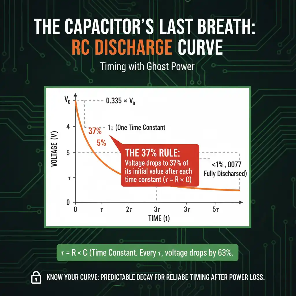
Discharge အဆင့်- 37% Rule
input ပါဝါကို ဖယ်ရှားလိုက်သောအခါ၊ capacitor သည် relay coil resistance မှတဆင့် အားကုန်စပြုသည်။ capacitor တစ်လျှောက်ရှိ ဗို့အားသည် မျဉ်းဖြောင့်အတိုင်း မကျဆင်းပါ—၎င်းသည် အောက်ပါတို့မှ အုပ်ချုပ်သော exponential decay curve ကို လိုက်နာသည် RC time constant:
τ (tau) = R × C
Where:
- τ = time constant (စက္ကန့်)
- R = resistance (ohms)
- C = capacitance (farads)
ဤတွင် လှပသောအပိုင်း- အချိန်တစ်ခု၏ တိကျသော time constant (τ) ပြီးနောက်၊ ဗို့အားသည် အတိအကျအထိ ကျဆင်းသွားလိမ့်မည် ၎င်း၏ ကနဦးတန်ဖိုး၏ 37%.
40% မဟုတ်ပါ။ 35% မဟုတ်ပါ။ အတိအကျ 37% (အမှန်တကယ် 36.8% သို့မဟုတ် ပိုမိုတိကျစွာပြောရလျှင် 1/e ဖြစ်ပြီး e ≈ 2.718)။.
၎င်းသည် ကျပန်းမဟုတ်ပါ—၎င်းသည် RC discharge ကို အုပ်ချုပ်သည့် exponential function တွင် ထည့်သွင်းထားသည်-
V(t) = V₀ × e^(-t/τ)
t = τ တွင်- V(τ) = V₀ × e^(-1) = V₀ × 0.368 = V₀ ၏ 37%
ဒါက ဘာကြောင့် အရေးကြီးသလဲ- နောက်ထပ် time constant တိုင်းသည် ဗို့အားကို နောက်ထပ် 37% ဖြင့် ကျဆင်းစေသည် ကျန်ရှိသော ဗို့အား။.
- 1τ တွင်- 37% ကျန်ရှိသည် (63% အားကုန်သွားသည်)
- At 2τ: 13.5% remaining (86.5% discharged)
- At 3τ: 5% remaining (95% discharged)
- At 5τ: 99% discharged)
For our 12V relay with 85Ω coil and 2200μF capacitor:
τ = 85Ω × 0.0022F = 0.187 seconds
After 0.187 seconds, the voltage across the capacitor (and thus across the relay coil) will be 4.4V. After 0.374 seconds (2τ), it’ll be 1.6V. After 0.56 seconds (3τ), just 0.6V.
But here’s the critical question: At what voltage does the relay coil actually release?
The Dropout Trick: Why Real Timing Is Longer Than Math Predicts
A 12V relay doesn’t need 12V to stay energized once it’s pulled in.
ဟိ pickup voltage (voltage needed to initially energize a de-energized relay) is typically 75-85% of rated voltage—call it 9-10V for a 12V relay. But the dropout voltage (voltage at which an already-energized relay releases) is much lower: typically 20-30% of rated voltage, or 2.4-3.6V for our 12V relay.
This happens because of the magnetic circuit’s hysteresis. When the relay armature is touching the pole piece (fully energized position), the air gap is zero, magnetic reluctance is minimized, and much less magnetomotive force (and thus less coil current/voltage) is needed to maintain the magnetic field holding the armature in place.
This means your timing extends well beyond the naive RC calculation.
Let’s recalculate for our 12V relay (85Ω coil, 2200μF capacitor) assuming a dropout voltage of 2.8V (23% of rated):
Using V(t) = V₀ × e^(-t/τ), solve for t when V(t) = 2.8V:
2.8V = 12V × e^(-t/0.187s)
0.233 = e^(-t/0.187s)
ln(0.233) = -t/0.187s
-1.46 = -t/0.187s
t = 0.273 seconds
So our 2200μF capacitor keeps the relay energized for 0.273 seconds, not the <0.1 seconds suggested by naive energy calculations.
ဒါက The Dropout Trick in action.
Want 5 seconds of hold-up time? Work backwards:
t_desired = 5 seconds, τ = RC = 0.187s (from earlier)
How many time constants is 5 seconds? 5s / 0.187s = 26.7 time constants
At 26.7τ, the voltage would be essentially zero—way below dropout. We need to solve for when voltage reaches 2.8V:
2.8/12 = 0.233, so we need: e^(-t/τ) = 0.233
-t/τ = ln(0.233) = -1.46
For t = 5s: τ = 5s / 1.46 = 3.42 seconds
Therefore: C = τ/R = 3.42s / 85Ω = 0.040F = 40,000μF
A 40,000μF capacitor at 12V? That’s physically large (roughly the size of a D-cell battery) and costs $15-25. Doable, but not elegant.
This is why latching relays (Method 2) or longer timing periods often use microprocessor-based designs with small batteries—the capacitor size becomes impractical beyond 30-60 seconds of continuous relay holding.
Sizing Your Capacitor: The 3-Step Method
Let’s work through a real-world design example: You need a 12V relay to stay energized for 10 seconds after power removal.
Step 1: Know Your Relay’s Specs
What you need:
- Coil voltage: 12V DC
- Coil resistance: Measure with a multimeter or check datasheet (let’s say 80Ω)
- Dropout voltage: Either test empirically or estimate at 25% of rated = 3.0V
If you don’t have the dropout voltage, test it: Apply rated voltage to the relay coil. Once energized, slowly reduce voltage with a variable power supply while monitoring the contacts. Note the voltage at which the relay releases. That’s your dropout voltage.
Pro-Tip #1: The dropout voltage is your friend. Most relay coils hold at 20-30% of rated voltage, giving you 3-5x more timing than naive energy calculations suggest.
Step 2: Calculate Required Capacitance
Use the dropout trick formula derived earlier:
t = -τ × ln(V_dropout / V_initial)
Where τ = RC, so:
t = -RC × ln(V_dropout / V_initial)
Rearrange to solve for C:
C = -t / [R × ln(V_dropout / V_initial)]
For our example:
- t = 10 seconds
- R = 80Ω
- V_initial = 12V
- V_dropout = 3.0V
C = -10s / [80Ω × ln(3.0V / 12V)]
C = -10s / [80Ω × ln(0.25)]
C = -10s / [80Ω × (-1.386)]
C = 10s / 110.9
C = 0.090F = 90,000μF
ဒါက သီအိုရီအရ အနည်းဆုံးပဲ။.
အဆင့် ၃: လက်တွေ့ကမ္ဘာ့အချက်တွေကို ထည့်တွက်ပါ။
ဒီမှာ သီအိုရီနဲ့ လက်တွေ့ တွေ့ဆုံတယ်။ အချက်သုံးချက်က မင်းရဲ့အချိန်ကို ခိုးယူလိမ့်မယ်။
အချက် ၁: Capacitor ယိုစိမ့်မှု လျှပ်စီးကြောင်း
တကယ့် capacitor တွေက ပြီးပြည့်စုံတဲ့ လျှပ်ကာတွေ မဟုတ်ဘူး။ ယိုစိမ့်မှု လျှပ်စီးကြောင်းက အပြိုင်ထုတ်လွှတ်တဲ့ လမ်းကြောင်းကို ပေးစွမ်းပြီး အချိန်ကို ထိရောက်စွာ လျှော့ချပေးတယ်။ electrolytic capacitor တွေအတွက် ယိုစိမ့်မှုက အခန်းအပူချိန်မှာ 0.01CV ကနေ 0.03CV (μA per μF-V) ဖြစ်နိုင်တယ်။.
ကျွန်တော်တို့ရဲ့ 90,000μF/12V capacitor အတွက်: ယိုစိမ့်မှု ≈ 0.02 × 90,000μF × 12V = 21,600μA = 21.6mA
အဲဒါကို relay coil ရဲ့ dropout မှာရှိတဲ့ လျှပ်စီးကြောင်း (3V / 80Ω = 37.5mA) နဲ့ နှိုင်းယှဉ်ကြည့်ပါ။ ယိုစိမ့်မှု လျှပ်စီးကြောင်းက relay coil ထက် လျှပ်စီးကြောင်းရဲ့ ထက်ဝက်ကျော်ကို သုံးစွဲနေတယ်။
ဖြေရှင်းချက်: အရေးကြီးတဲ့ အချိန်အသုံးပြုမှုတွေအတွက် ယိုစိမ့်မှုနည်းတဲ့ film capacitor တွေကို (polypropylene သို့မဟုတ် polyester) သုံးပါ၊ ဒါမှမဟုတ် electrolytic တွေအတွက် 30-50% capacitance margin ကို ထည့်ပါ။.
Pro-Tip: Capacitor ယိုစိမ့်မှု လျှပ်စီးကြောင်းက မင်းရဲ့အချိန်ကို ခိုးယူတယ်။ 10 စက္ကန့်ထက်ပိုတဲ့ နှောင့်နှေးမှုတွေအတွက် film capacitor တွေကို (polypropylene/polyester) သုံးပါ၊ electrolytic တွေကို မသုံးပါနဲ့။.
အချက် ၂: အပူချိန် အကျိုးသက်ရောက်မှုများ
Capacitor ယိုစိမ့်မှု လျှပ်စီးကြောင်းက အပူချိန် 10°C တိုးတိုင်း နှစ်ဆနီးပါး တိုးလာတယ်။ 25°C မှာ 20mA ယိုစိမ့်မှုရှိတဲ့ capacitor တစ်ခုဟာ 35°C မှာ 40mA၊ 45°C မှာ 80mA ဖြစ်နိုင်တယ်။.
Relay dropout ဗို့အားကလည်း အပူချိန်နဲ့အမျှ ပြောင်းလဲတတ်တယ်—ပုံမှန်အားဖြင့် အပူချိန်နဲ့အမျှ coil ခုခံမှု တိုးလာတာနဲ့အမျှ အနည်းငယ် တိုးလာတတ်တယ် (ကြေးနီရဲ့ အပြုသဘောဆောင်တဲ့ အပူချိန်ကိန်းဂဏန်း)။ ဒါက အနည်းငယ် အထောက်အကူဖြစ်ပေမယ့် capacitor ယိုစိမ့်မှုကို လျော်ကြေးပေးဖို့ လုံလောက်မှု မရှိဘူး။.
အချက် ၃: Capacitor ခံနိုင်ရည်
Electrolytic capacitor တွေမှာ အများအားဖြင့် -20%/+80% ခံနိုင်ရည် ရှိတယ်။ အဲဒီ 90,000μF capacitor က တကယ်တော့ 72,000μF ဖြစ်နိုင်တယ် (-20% မှာ)။ Film capacitor တွေက ပိုတင်းကျပ်တယ်၊ ပုံမှန်အားဖြင့် ±5-10%။.
ဘေးကင်းရေး အနားသတ်ကို အသုံးပြုပါ:
ဒီအချက်တွေကို ထည့်သွင်းစဉ်းစားပြီး မင်းရဲ့ တွက်ချက်ထားတဲ့ capacitance ကို အပူချိန်နဲ့ component ခံနိုင်ရည်ကို ဖြတ်ကျော်ပြီး ယုံကြည်စိတ်ချရတဲ့ လုပ်ဆောင်မှုအတွက် 1.5 ကနေ 2.0x နဲ့ မြှောက်ပါ။
C_actual = 90,000μF × 1.75 = 157,500μF
စံတန်ဖိုးတစ်ခုအထိ ပင့်တင်ပါ: 2 × 82,000μF = 164,000μF ကို အပြိုင်ဆက်သွယ်ပါ။, ဒါမှမဟုတ် ရနိုင်ရင် 150,000μF capacitor တစ်ခုတည်းကို သုံးပါ။.
12V မှာ 150,000μF electrolytic capacitor တစ်ခုဟာ ရုပ်ပိုင်းဆိုင်ရာအရ အချင်း 35mm × အမြင့် 60mm ရှိပြီး ၈-၁၅ ဒေါ်လာလောက် ကုန်ကျပြီး ခန့်မှန်းခြေအားဖြင့် 10.8 joule ကို သိုလှောင်ထားတယ်။.
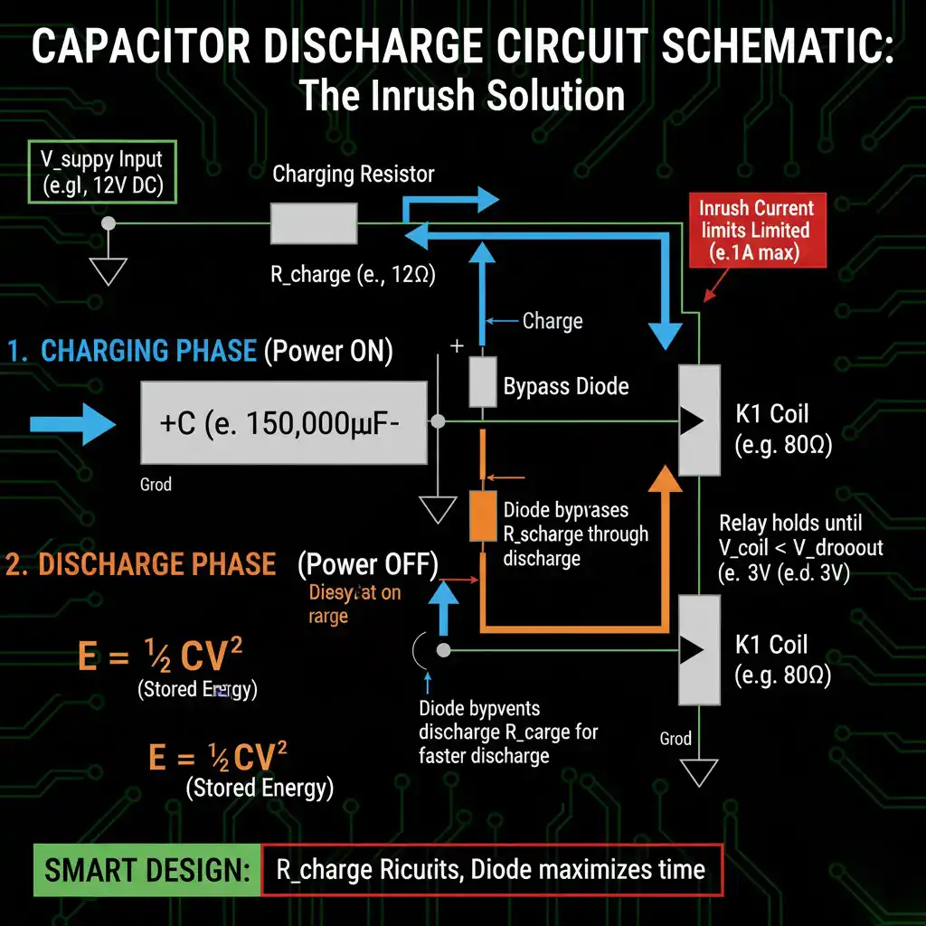
Inrush လျှပ်စီးကြောင်း ကန့်သတ်ခြင်း: အားသွင်းခုခံကို မမေ့ပါနဲ့။
မင်း ပထမဆုံး ပါဝါထည့်တဲ့အခါ အားမသွင်းရသေးတဲ့ capacitor အကြီးကြီးက ဝါယာရှော့ဖြစ်သလိုမျိုး မြင်ရတယ်။ 0V ကနေ 12V အထိ ခုခံမှုမရှိဘဲ အားသွင်းနေတဲ့ 150,000μF capacitor တစ်ခုဟာ သီအိုရီအရ အဆုံးမရှိတဲ့ လျှပ်စီးကြောင်းကို တောင်းဆိုလိမ့်မယ်။.
လက်တွေ့မှာ ဝါယာကြိုး ခုခံမှုနဲ့ ပါဝါထောက်ပံ့မှု impedance က ဒါကို ကန့်သတ်ထားပေမယ့် ပထမ millisecond အနည်းငယ်အတွက် 10-50A inrush လျှပ်စီးကြောင်းတွေကို မင်း မြင်ရဦးမယ်၊ အဲဒါက contacts တွေ၊ fuses တွေ ဒါမှမဟုတ် ပါဝါထောက်ပံ့မှုကိုယ်တိုင်ကို ပျက်စီးစေနိုင်တယ်။.
ဖြေရှင်းချက်: Inrush လျှပ်စီးကြောင်းကို ကန့်သတ်ဖို့ capacitor နဲ့ ဆက်တိုက် အားသွင်းခုခံ (R_charge) ကို ထည့်ပါ၊ ထုတ်လွှတ်နေစဉ်အတွင်း ရှောင်ကွင်းဖို့ အပြိုင် diode တစ်ခုနဲ့ ထည့်ပါ:
[ပါဝါဝင်] → [R_charge] → [+Capacitor-] → [Relay Coil] → [မြေပြင်]
Diode က capacitor ကို relay coil (ဆက်တိုက် ခုခံမှု မရှိ) မှတဆင့် တိုက်ရိုက် ထုတ်လွှတ်ဖို့ ခွင့်ပြုပြီး R_charge မှတဆင့် အားသွင်းလျှပ်စီးကြောင်းကို အတင်းအကျပ် ပို့ဆောင်ပေးတယ်။.
R_charge အရွယ်အစား အားသွင်းလျှပ်စီးကြောင်းကို သင့်တင့်လျောက်ပတ်တဲ့ အဆင့် (0.5-2A) အထိ ကန့်သတ်ဖို့:
R_charge = V_supply / I_charge_max = 12V / 1A = 12Ω
ဒါက အားသွင်းနေစဉ်အတွင်း RC အချိန်ကိန်းသေကို 12Ω ထပ်ထည့်ပေးတယ်၊ အားအပြည့်သွင်းဖို့ အချိန်ကို 5τ = 5 × (12Ω + 80Ω) × 0.15F = 69 စက္ကန့်အထိ တိုးချဲ့ပေးတယ်။.
အဲဒါက အရမ်းကြာနေရင် R_charge ကို လျှော့ချပါ ဒါပေမယ့် inrush ပိုများတာကို လက်ခံပါ (ဥပမာ 6Ω အတွက် ~2A inrush၊ 35 စက္ကန့် အားသွင်းချိန်)။ အပေးအယူက မင်းရဲ့အပေါ်မှာ မူတည်တယ်။.
Pro-Tip: RC အချိန်ကိန်းသေ (τ = RC) က အစမှတ်ပဲ—တကယ့် hold-up အချိန်က မင်းရဲ့ capacitor ထုတ်လွှတ်မှုမျဉ်းနဲ့ ကိုက်ညီတဲ့ relay coil ခုခံမှုအပေါ်မှာ မူတည်တယ်။.
Capacitor ရွေးချယ်မှု: အမျိုးအစားက အရွယ်အစားထက် ဘာကြောင့် ပိုအရေးကြီးတာလဲ။
မင်း capacitance ကို တွက်ချက်ပြီးပြီ။ အခု မင်း တကယ့် component ကို ရွေးချယ်ဖို့ လိုတယ်။ Capacitor ဓာတုဗေဒက အချိန်အသုံးပြုမှုတွေမှာ စွမ်းဆောင်ရည်ကို သိသိသာသာ သက်ရောက်မှုရှိတယ်—အရွယ်အစားက အရာအားလုံး မဟုတ်ဘူး။.
Film Capacitor နဲ့ Electrolytic: ယိုစိမ့်မှု စစ်ပွဲ
Electrolytic Capacitor (အလူမီနီယမ် သို့မဟုတ် Tantalum):
အားသာချက်များ
- ယူနစ်ထုထည်တစ်ခုအတွက် အမြင့်ဆုံး capacitance (တန်ဖိုးကြီးတွေအတွက် အရေးကြီးတယ်)
- microfarad တစ်ခုအတွက် ကုန်ကျစရိတ် သက်သာတယ် (1000μF အတွက် ၀.၀၅-၀.၁၅ ဒေါ်လာ)
- ဗို့အားမြင့်တွေမှာ အလွယ်တကူ ရနိုင်တယ်
အားနည်းချက်များ-
- ယိုစိမ့်မှု လျှပ်စီးကြောင်း မြင့်မားတယ် (0.01-0.03 CV spec၊ လက်တွေ့မှာ ပိုဆိုးတယ်)
- ဝင်ရိုးစွန်းကို ထိလွယ်ရှလွယ်တယ် (ဗို့အားပြောင်းပြန် = ချက်ချင်း သေဆုံး)
- သက်တမ်း ကန့်သတ်ထားတယ် (electrolyte က ၅-၁၀ နှစ်အတွင်း ခြောက်သွေ့သွားတယ်)
- အပူချိန်ကို ထိလွယ်ရှလွယ်တဲ့ capacitance နဲ့ ယိုစိမ့်မှု
အတွက် အကောင်းဆုံး အရွယ်အစားနဲ့ ကုန်ကျစရိတ်က လွှမ်းမိုးထားတဲ့ ၃၀ စက္ကန့်အောက် အချိန်နှောင့်နှေးမှုတွေ၊ ဒါမှမဟုတ် ယိုစိမ့်မှုအတွက် 1.5-2x margin ကို ထည့်ထားတဲ့ နေရာတွေမှာ သုံးတယ်။.
Film Capacitor (Polypropylene, Polyester, Polycarbonate):
အားသာချက်များ
- ယိုစိမ့်မှု လျှပ်စီးကြောင်း အလွန်နည်းတယ် (<0.001 CV၊ electrolytic တွေထက် 10-100x လောက် နည်းတယ်)
- အပူချိန် တည်ငြိမ်မှု ကောင်းမွန်တယ်
- သက်တမ်းရှည်တယ် (၂၀+ နှစ်)
- ဝင်ရိုးစွန်း ကန့်သတ်ချက် မရှိဘူး (AC ဒါမှမဟုတ် ပြောင်းပြန် DC ကို ကိုင်တွယ်နိုင်တယ်)
အားနည်းချက်များ-
- တူညီတဲ့ capacitance အတွက် ရုပ်ပိုင်းဆိုင်ရာ အရွယ်အစား ပိုကြီးတယ်
- ကုန်ကျစရိတ် ပိုများတယ် (1000μF အတွက် ၀.၅၀-၂.၀၀ ဒေါ်လာ)
- capacitance တန်ဖိုး နည်းပါးတာကိုပဲ ကန့်သတ်ထားတယ် (လက်တွေ့မှာ သင့်တင့်လျောက်ပတ်တဲ့ အရွယ်အစားအတွက် <50μF)
အတွက် အကောင်းဆုံး ၃၀ စက္ကန့်ထက် ပိုတိကျတဲ့ အချိန်အသုံးပြုမှု၊ အပူချိန်မြင့်မားတဲ့ ပတ်ဝန်းကျင်တွေ ဒါမှမဟုတ် ရေရှည် ရွေ့လျားမှုက လက်မခံနိုင်တဲ့ အသုံးပြုမှုတွေမှာ သုံးတယ်။.
Hybrid ချဉ်းကပ်မှု: အကောင်းဆုံး နှစ်ခုစလုံး
၃၀-၆၀ စက္ကန့်အတွင်း အချိန်အသုံးပြုမှုအတွက် ထည့်သွင်းစဉ်းစားပါ။ အပြိုင်ပေါင်းစပ်မှု:
- အစုလိုက်အပြုံလိုက် စွမ်းအင်သိုလှောင်မှုအတွက် ကြီးမားတဲ့ electrolytic (တွက်ချက်ထားတဲ့ capacitance ရဲ့ ၈၀%)
- ယိုစိမ့်မှုနည်းတဲ့ တိကျမှုအတွက် သေးငယ်တဲ့ film capacitor (တွက်ချက်ထားတဲ့ capacitance ရဲ့ ၂၀%)
ဥပမာ: 120,000μF electrolytic + 30,000μF film = စုစုပေါင်း 150,000μF
Film cap က electrolytic ယိုစိမ့်မှုကို လျော်ကြေးပေးပြီး သီအိုရီ တွက်ချက်မှုတွေနဲ့ ပိုနီးကပ်တဲ့ အချိန်ကို တိုးချဲ့ပေးတယ်။ ကုန်ကျစရိတ် တိုးလာမှုက သင့်တင့်လျောက်ပတ်တယ် (electrolytic အားလုံးထက် ၃၀% ပိုများတယ်)၊ ဒါပေမယ့် အချိန်တိကျမှုက သိသိသာသာ တိုးတက်လာတယ်။.
အဖြစ်များတဲ့ အမှားတွေနဲ့ ပြင်ဆင်မှုတွေ
အမှား ၁: ထောက်ပံ့ဗို့အားအောက် အဆင့်သတ်မှတ်ထားတဲ့ capacitor တွေကို သုံးခြင်း
A 12V supply needs 16V-rated (or higher) capacitors for reliability. Voltage transients, ripple, and component tolerance mean a “12V system” might see 14-15V under certain conditions. Operating a capacitor near its voltage rating accelerates failure and increases leakage.
ပြင်ဆင်ခြင်း- Use capacitors rated at least 1.3x supply voltage (16V for 12V systems, 25V for 18V, etc.)
Mistake #2: Ignoring ESR (Equivalent Series Resistance)
Capacitors have internal resistance (ESR) that appears in series with the ideal capacitance. High ESR reduces available discharge current and creates voltage drop under load, effectively reducing hold-up time.
Large electrolytics might have ESR of 0.1-1Ω. For a relay coil drawing 150mA at dropout, 1Ω ESR means 0.15V lost to internal resistance—enough to reduce your margin.
ပြင်ဆင်ခြင်း- Check ESR specs. For timing applications, prefer low-ESR types (0.1Ω or less).
Mistake #3: Parallel connection without current balancing
Connecting multiple capacitors in parallel (say, four 10,000μF caps instead of one 40,000μF) works great in theory but can cause problems if capacitors have mismatched ESR or leakage. The “better” capacitor does more work, ages faster, and fails first—then the remaining caps are suddenly undersized.
ပြင်ဆင်ခြင်း- Use matched capacitors from the same manufacturing batch when paralleling. Add small series resistors (0.1-0.5Ω) to each capacitor to force current sharing.
Pro-Tip #4: The latching relay trick gives you 1/10th the capacitor size for the same timing by using mechanical memory instead of continuous power.

The Ghost Power Timer: Timing That Survives the Power Loss
True off-delay relays solve a fundamental paradox: how do you measure time when the clock’s power source disappears?
The answer lives in The Capacitor’s Last Breath—stored electrical energy that exhales gradually, powering relay coils and timing circuits for seconds or minutes after input power vanishes. It’s ghost power: enough juice to complete one last task before fading to zero.
Three methods achieve this:
- Capacitor discharge (most common)—RC time constants turn energy storage into precise timing
- Latching relay + small capacitor (most efficient)—mechanical memory needs only pulse energy
- Small battery backup (longest hold-up)—microamp consumption enables hours of timing
The physics is elegant: The 37% Rule governs exponential RC discharge, but The Dropout Trick extends practical timing by 3-5x beyond naive calculations by exploiting relay hysteresis.
A $2 film capacitor and a $5 relay can achieve what once required a $200 pneumatic timer—smaller, cheaper, more reliable, and field-adjustable.
Modern control systems demand timing that survives power interruptions. Whether it’s cooling fans preventing bearing damage, process valves completing shutdown sequences, or safety circuits maintaining protection during transients, the true off-delay relay delivers timing insurance when standard electronics would fail.
VIOX ELECTRIC offers a complete range of electronic timing relays including true off-delay models with capacitor-based energy storage, suitable for motor control, process automation, and safety applications. Our timing relays meet IEC 61810 standards and provide reliable operation across industrial temperature ranges (-25°C to +70°C ambient).
For technical specifications and selection guidance, contact our application engineering team. We’ll help you size the right timing solution for your application—no ghost power required on our end.
