
နိဒါန်း
Wiring a solar panel junction box is the critical foundation of any photovoltaic (PV) system’s reliability and safety. Whether you’re installing a small residential array or a larger commercial system, understanding how to properly wire and connect your solar panels directly impacts system efficiency, longevity, and—most importantly—safety. Improperly wired junction boxes are a leading cause of solar-related fires, electrical failures, and warranty voidance.
This comprehensive guide walks you through every step of the process, from preparing UV-rated PV cables to securing MC4 connectors with professional-grade techniques. You’ll learn the same safety standards used by certified installers worldwide, along with industry best practices that meet NEC 690 နှင့် IEC 61010 regulations.
What is a Solar Panel Junction Box?
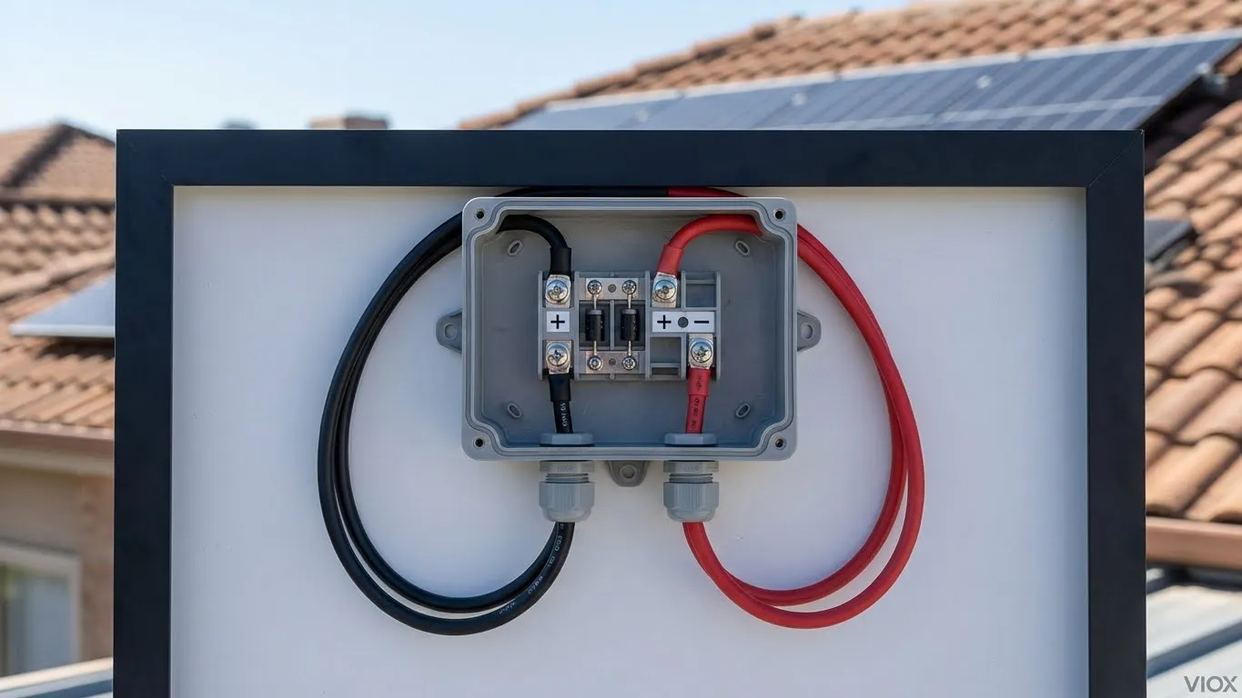
A solar panel junction box is the sealed electrical enclosure mounted on the back of each solar module. It serves three critical functions:
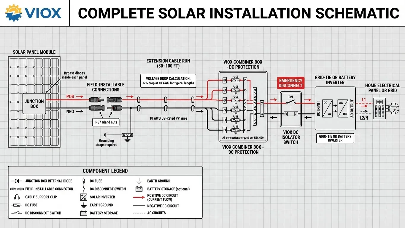
- Connection Hub: The junction box merges internal panel wiring with external PV cables, routing power to your inverter or ပေါင်းစပ်ဘောက်စ်.
- Safety Component: It houses bypass diodes that prevent “hot spots” (areas of excessive heat) when one panel is shaded while others are in full sun.
- ရာသီဥတုကာကွယ်ရေး- A sealed, IP65/IP67-rated enclosure ensures moisture, dust, and insects cannot corrode or damage internal electrical components.
Understanding these functions is essential because mistakes in junction box wiring can result in:
- Arc flash incidents (potentially lethal)
- Moisture-induced corrosion and short circuits
- Reduced system output by 15–30%
- ပြီးပြည့်စုံသောစနစ်ပျက်ကွက်
Tools and Materials You’ll Need
Before beginning any wiring work, gather the following industry-standard tools:
| Tool/Material | အင္တာနက္စာမ်က္ႏွာ | ရည်ရွယ်ချက် | ဘာကြောင့် အရေးကြီးတာလဲ။ |
|---|---|---|---|
| PV Wire | 10 AWG, USE-2 or PV rated, UV-resistant | Main conductor | Standard cable minimizes voltage drop; non-UV wire degrades in sunlight |
| Wire Strippers | Precision model, 1/16″ tolerance | Expose clean copper | Nicking the conductor creates weak points and corrosion zones |
| Flathead Screwdriver | 3/16″ or 1/4″ | Open junction box cover | Wrong size can strip screw heads |
| MC4 Crimper | Ratcheting style, not pliers | Crimp male/female pins | Ratchet crimpers ensure consistent “gas-tight” pressure |
| Heat Shrink Tubing | Adhesive-lined, UV-rated | Waterproof insulation | Creates secondary moisture barrier |
| MC4 Spanners | Staubli original or equivalent | Tighten gland nuts | Prevents over-torquing and connector damage |
| မာလ်မီတာ | DCV + Resistance modes | Test for polarity & faults | Essential for safety verification |
| Insulated Gloves | 1000V rated | Personal protection | DC cannot be safely touched ungloved |
| Torque Screwdriver (တင်းအားချိန်ညှိဝက်အူလှည့်) | 0.5–2.5 Nm range | Terminal block fastening | Loose connections are the #1 cause of solar fires |
အစွန်အဖျား: Many solar professionals use “cold work” gloves (cotton-backed rubber) over insulated gloves for better dexterity while maintaining protection.
Step 1: Safety First – Understanding Hazards
Solar panels are “always on” in daylight. Even on a cloudy day or when partially shaded, they generate dangerous DC voltage.
Critical Safety Measures:
- Cover the Panel: Place an opaque tarp or cardboard over the solar array to halt power generation. Measure voltage before starting; it should read zero.
- Disconnect DC Isolators: If your system includes a DC ဖြတ်တောက်ခလုတ် (between panels and inverter), switch it to “OFF” and verify via multimeter.
- Use Insulated Tools: Standard metal screwdrivers conduct electricity. Use tools rated for 1000V electrical work.
- Wear PPE: Insulated gloves, safety glasses, and rubber-soled shoes are mandatory.
- Never Work Alone: Have a partner present who can call emergency services if needed.
အဘယ်ကြောင့်ဤအရေးကြီး: A single slip while holding a DC-powered wire can cause ventricular fibrillation (VF). Solar panel DC voltage, even from a small 2–3 kW array, is often 300–600V—well above the 50V threshold that is considered lethal.
Step 2: Prepare the PV Conductors
Proper wire preparation is where many installations begin to fail.
Detailed Procedure:
- Measure and Cut: Cut two lengths of 10 AWG PV wire—one for the positive lead, one for negative. Add 6–12 inches of extra length to allow for future maintenance without re-running new wire.
- Strip the Wire: Using a precision wire stripper:
- Set the stripper for 10 AWG.
- Insert the wire end and rotate the stripper 2–3 times.
- Pull the insulation off with gentle pressure.
- Expose 1/4 to 1/2 inch (6–12mm) of bare copper.
- အရေးကြီးသည်- Do NOT nick or cut any copper strands—each nick reduces current capacity.
- Inspect the Copper: Look at the exposed end under good light. All copper should be shiny and intact. If you see black oxidation, use a soft brass wire brush to clean it.
- Test for Nicks: Gently tug on the insulation; it should not slide. If it does, re-strip and expose a fresh section of conductor.
Step 3: Open and Inspect the Junction Box
The First Look:
- Using a small flathead screwdriver, carefully pry open the junction box cover. Most boxes have 4 screws or a snap-on lid. Set screws aside in a labeled container.
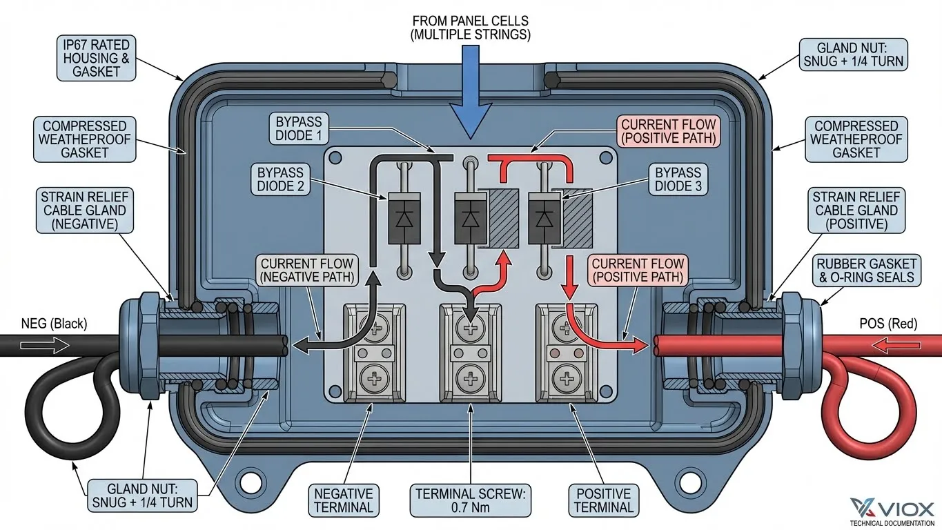
- Inside, you’ll see:
- Two or three terminals (negative, positive, and sometimes a ground terminal).
- Bypass diodes (small rectangular components soldered to internal wires).
- Internal PV cables (thin ribbon-like wires connecting the diodes to the terminals).
သတိပေးချက်- Do NOT disturb internal diodes or ribbon wires. Touching them can break internal connections and destroy the panel.
- Locate Polarity Markings:
- ကိုလိုက်ရှာနေသည် (+) နှင့် (–) symbols inside the box.
- Red wires typically connect to (+); black to (–).
- Verify with a multimeter by touching the red probe to the (+) terminal and black to (–); you should see an open circuit voltage (Voc) around 35–45V per panel.
Step 4: Feed Wires Through Cable Glands
Cable glands (also called strain relief connectors) are where water and dust typically breach a junction box.
Professional Installation Technique:
- Identify the Glands: Locate the rubber strain relief connectors on the left (negative) and right (positive) sides of the box.
- Thread the Negative Lead: Slide the black PV cable through the negative side gland. The gland nut should hand-tighten (do not over-tighten yet).
- Thread the Positive Lead: Repeat with the red cable on the positive side.
- Create a “Drip Loop”: Before entering the box, bend each cable into a downward U-shape about 6 inches below the box. This prevents rain from running along the cable into the gland.
Step 5: Secure Connections to Terminals
Terminal tightness is your first line of defense against fires.
Terminal Torquing Procedure (NEC 690.31):
- Position the Wire: Insert the stripped end of the negative cable into the negative terminal. Ensure at least 1/4 inch of bare copper is inside the terminal.
- Tighten with Torque Screwdriver: Using a 0.5–0.7 Nm torque screwdriver (or a manual screwdriver, tightened until “snug plus 1/4 turn”), secure the terminal screw.
- Crimp the Strain Relief: Use a wire crimper to form a tight barrel crimp around the exposed portion of the negative cable, just outside the terminal. This locks the wire in place and prevents pull-out.
- Repeat for Positive: Follow the same steps for the positive (red) lead.
- Verify Tightness: Give each wire a firm tug; it should not budge.
Common Mistakes:
- Twisting stranded wire together and forcing it into the terminal (use a ring or spade connector for better contact).
- Under-tightening (leads to arcing and fire).
- Over-tightening (can break terminal screws).
Step 6: Understanding and Installing MC4 Connectors
MC4 ချိတ်ဆက်ကိရိယာများ have become the industry standard because they’re weatherproof, keyed to prevent reverse polarity, and compatible across major panel brands.
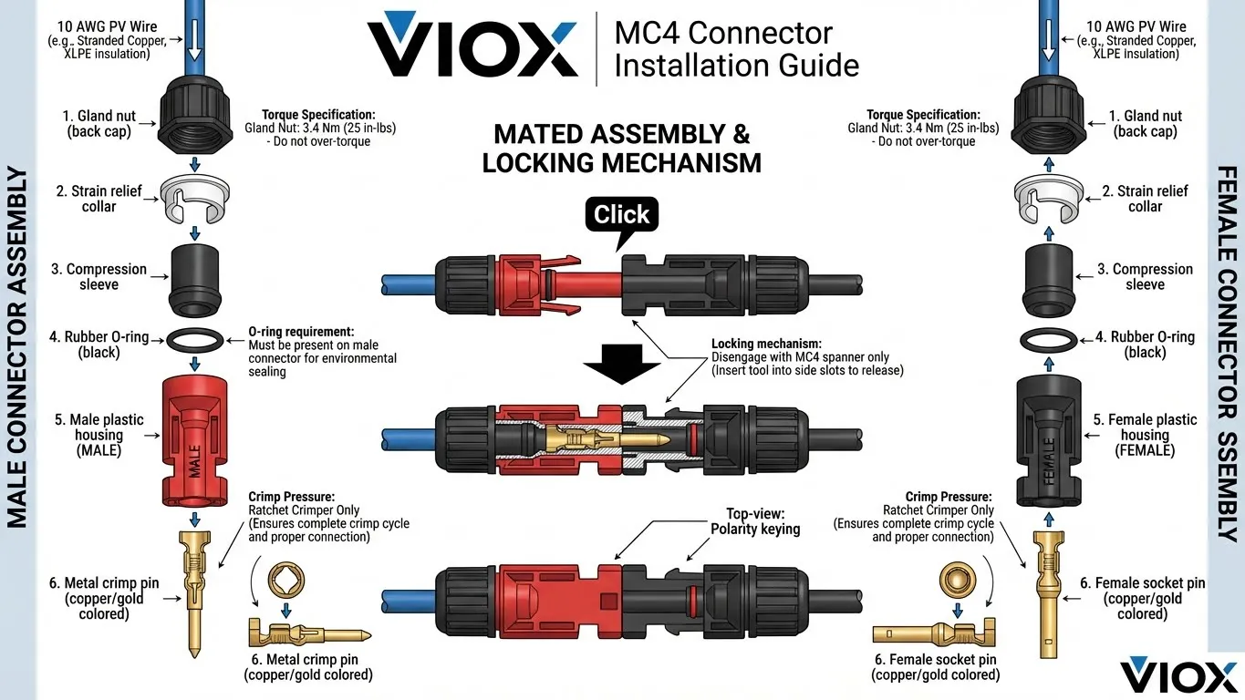
Anatomy of an MC4 Connector:
- Male Connector (used for positive/red wire) – metal pin inside.
- Female Connector (used for negative/black wire) – socket inside.
- Metal Crimp Pin – the critical component carrying current.
- Strain သက်သာခြင်း။ – plastic collar providing mechanical support.
- Gland Nut – back cap that tightens for a waterproof seal.
- Rubber O-Ring – seals out moisture.
- Locking Tabs – ensure connectors stay mated under vibration.
Step 7: Perfect the MC4 Crimp
A bad crimp is the #1 cause of solar installation failures and fires. Here’s the professional method:
ခိုင်ခံ့အောင်ပြုလုပ်ခြင်းလုပ်ငန်းစဉ်
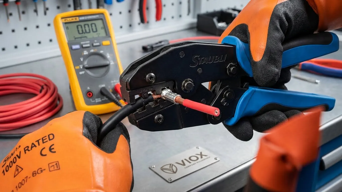
- Prepare the Pin: Take a male copper crimp pin (for the positive/red lead) and examine it under light. It should be shiny, not oxidized.
- Set the Crimper: Use a ratcheting MC4 crimper and set it for 10 AWG wire. The ratchet ensures consistent pressure.
- Insert and Crimp: Slide the stripped end of the red wire fully into the crimp pin barrel. Squeeze the crimper handles until it releases (you’ll hear a click).
- Verify the Crimp: Pull gently on the wire—it should not slide. If it does, the crimp failed; discard the pin and try again.
- Slide on Protective Components: Before inserting the pin into the connector housing, slide the following components onto the wire in order:
- Rubber gland nut (the back cap)
- Compression sleeve
- Rubber O-ring seal
- Insert and Lock: Push the crimped pin into the MC4 male housing until you hear a distinct click.
- Tighten the Gland: Use MC4 spanners to tighten the back nut by approximately 3.4 Nm (25 in-lbs). The connection should be hand-tight with no visible gaps.
- Repeat for Negative: Follow the same steps using a female connector for the black/negative wire.
Critical Testing:
- အမြင်အာရုံစစ်ဆေးခြင်း- No melting, discoloration, or warping of plastic.
- The “Click” Test: Connectors should mate with a definite click.
- Temperature Test: After installation, use a thermal camera to verify the connector is not warmer than the surrounding cable.
Step 8: Extending PV Cables
Most installations require cables longer than what exits the junction box. VIOX manufactures PV cables and MC4 ချိတ်ဆက်ကိရိယာများ for safe field extensions.
Extension Cable Installation:
| Cable Length | Recommended AWG | ဗို့အားကျဆင်းမှု | အဘယ်ကြောင့် ဤအရာသည် အရေးကြီးသနည်း။ |
|---|---|---|---|
| 0–50 ft | 10 AWG | <2% | Standard residential; no efficiency loss |
| 50–100 ft | 8 AWG | ~2% | Longer runs require larger conductors |
| 100–200 ft | 6 AWG | ~1.5% | Commercial/ground-mount arrays |
| > ပေ ၂၀၀ ကျော် | 4 AWG သို့မဟုတ် တွဲပြေးခြင်း | <1% | အသုံးချမှုအဆင့်; ဗို့အားမြင့်စနစ်များ |
တိုးချဲ့ခြင်းလုပ်ငန်းစဉ်:
- တိုးချဲ့ကြိုးအဆုံးများကို ပြင်ဆင်ပါ (၁/၄–၁/၂ လက်မ ခွာပါ) နှင့် အဆင့် ၇ တွင် ဖော်ပြထားသည့်အတိုင်း တူညီသော ကျွမ်းကျင်သော နည်းပညာကို အသုံးပြု၍ သင့်လျော်သော MC4 ချိတ်ဆက်ကိရိယာများကို အသုံးပြုပါ။.
- အရေးကြီးသည်- Positive သည် positive သို့ ချိတ်ဆက်သည် (အမျိုးသားမှ အမျိုးသားသို့ အမျိုးသမီး coupler မှတဆင့်)၊ negative သည် negative သို့ ချိတ်ဆက်သည်။.
- ခေါင်မိုး သို့မဟုတ် ထိန်သိမ်းခြင်းအတွက် UV အဆင့်သတ်မှတ်ထားသော ကြိုးကလစ်များကို ၃ ပေတိုင်း အသုံးပြု၍ ကြိုးများကို လုံခြုံအောင်ထားပါ။.
- ကြိုးများကို လွတ်လွတ်လပ်လပ် မဆွဲထားပါနှင့် (အလေးချိန်သည် အတွင်းပိုင်း ချိတ်ဆက်မှု ဖိအားကို ဖြစ်စေသည်)။.
- အရောင်ကုဒ် သို့မဟုတ် ပုံနှိပ်တံဆိပ်များကို အသုံးပြု၍ junction box နှင့် inverter နှစ်ခုလုံးရှိ ကြိုးများကို တံဆိပ်ကပ်ပါ။.
အဆင့် ၉: MC4 ချိတ်ဆက်ကိရိယာများကို ဖြုတ်တပ်ခြင်းနှင့် ပြဿနာဖြေရှင်းခြင်း
ဘေးကင်းစွာ ဖြုတ်တပ်ခြင်းသည် arc flash ထိခိုက်ဒဏ်ရာရခြင်းနှင့် စက်ပစ္စည်းပျက်စီးခြင်းကို ကာကွယ်ပေးသည်။.
ဘေးကင်းစွာ ဖြုတ်တပ်ခြင်း လုပ်ငန်းစဉ်:
- Inverter ကို ပိတ်ပါ: inverter ကို “standby” သို့မဟုတ် “off” mode သို့ ထားပါ။.
- ဗို့အား သုညကို စစ်ဆေးပါ: ချိတ်ဆက်ကိရိယာများကြားတွင် 0V DC ရှိမရှိကို အတည်ပြုရန် multimeter ကို အသုံးပြုပါ။.
- MC4 Spanner ကို အသုံးပြုပါ: spanner prongs ကို အမျိုးသမီးချိတ်ဆက်ကိရိယာရှိ လော့ခ်ချသည့် tab များနှင့် ညှိပြီး စက်ပိုင်းဆိုင်ရာ လော့ခ်ကို လွှတ်ရန် ဖြည်းညှင်းစွာ နောက်သို့ ဆွဲပါ။.
- ဖြည်းညှင်းစွာ ခွဲထုတ်ပါ: လော့ခ်လွှတ်ပြီးသည်နှင့် ချိတ်ဆက်ကိရိယာများကို ဂရုတစိုက် ဆွဲထုတ်ပါ။ အတင်းအကျပ် မဆွဲပါနှင့်။.
- ပွင့်နေသော ချိတ်ဆက်ကိရိယာများကို အုပ်ပါ: array ကို နာရီအနည်းငယ်ထက်ပို၍ လျှပ်စစ်ဓာတ်အားဖြတ်တောက်မည်ဆိုပါက၊ ပွင့်နေသော positive ချိတ်ဆက်ကိရိယာအဆုံးများကို လျှပ်ကာတိပ် သို့မဟုတ် အဖုံးများဖြင့် အုပ်ထားပါ။.
ခုခံမှုမြင့်မားသော ချိတ်ဆက်ကိရိယာများ၏ ပြဿနာဖြေရှင်းခြင်း:
| လက္ခဏာ | အကြောင်းရင်း | ဖြေရှင်းနည်း |
|---|---|---|
| ချိတ်ဆက်ကိရိယာများသည် ထိတွေ့ရန် နွေးထွေးနေသည် | ခုခံမှုမြင့်မားသော crimp သို့မဟုတ် ချောင်နေသော pins | ချိတ်ဆက်မှုကို ဖြုတ်ပါ၊ pin အသစ်များဖြင့် ပြန်လည် crimp လုပ်ပါ သို့မဟုတ် ချိတ်ဆက်ကိရိယာကို အစားထိုးပါ |
| ကြားဖြတ်ပါဝါ သို့မဟုတ် ဗို့အားနည်းခြင်း | pin ပေါ်ရှိ သံချေးတက်ခြင်း သို့မဟုတ် မပြည့်စုံသော လော့ခ်ချခြင်း | ဆက်သွယ်မှုကို စမ်းသပ်ရန် multimeter ကို အသုံးပြုပါ။ ချိတ်ဆက်ကိရိယာကို သန့်ရှင်းပါ သို့မဟုတ် အစားထိုးပါ |
| ချိတ်ဆက်ကိရိယာသည် အလွယ်တကူ ကွဲထွက်သွားသည် | လော့ခ်ချသည့် tab များ မပါဝင်ပါ | သေချာသော click တစ်ခုအထိ ခိုင်မာစွာ ပြန်လည်တွဲဖက်ပါ။ အကယ်၍ လျော့ရဲနေသေးပါက အိမ်ရာကို အစားထိုးပါ |
| ချိတ်ဆက်ကိရိယာအတွင်းပိုင်း စိုထိုင်းဆ | Gland nut ကို မတင်းကျပ်ပါ။ O-ring ပျက်စီးခြင်း | ဖြုတ်ပါ၊ လုံးဝခြောက်သွေ့အောင်ထားပါ၊ O-ring ကို အစားထိုးပါ၊ torque ဖြင့် ပြန်လည်တပ်ဆင်ပါ |
လိုက်နာမှုနှင့် ဘေးကင်းရေး စံနှုန်းများ
သင်၏ တပ်ဆင်မှုသည် ဤစည်းမျဉ်းများနှင့် ကိုက်ညီရမည်:
- NEC 690 (အမျိုးသား လျှပ်စစ်ကုဒ်၊ နေရောင်ခြည်စွမ်းအင်သုံး Photovoltaic စနစ်များ) – Terminal torquing၊ ဝါယာကြိုးအရွယ်အစား၊ ဖြုတ်တပ်ခြင်း လုပ်ထုံးလုပ်နည်းများ.
- IEC 61010 (လျှပ်စစ်တိုင်းတာရေးကိရိယာအတွက် ဘေးကင်းရေးစံနှုန်းများ) – စမ်းသပ်ခြင်းနှင့် စစ်ဆေးခြင်းဆိုင်ရာ ပရိုတိုကောများ။.
- UL 4703 (PV Wire standard) – UV ခုခံမှုနှင့် အပူချိန်အဆင့်သတ်မှတ်ချက်များကို သေချာစေသည်။.
- IP65/IP67 အဆင့်သတ်မှတ်ချက် – သင်၏ junction box သည် ရေဂျက်များ (IP65) သို့မဟုတ် ယာယီနှစ်မြှုပ်ခြင်း (IP67) အတွက် အဆင့်သတ်မှတ်ထားရမည်။.
- Bypass Diode စမ်းသပ်ခြင်း – diode တစ်ခုစီသည် ဦးတည်ရာတစ်ခုတည်းတွင်သာ လျှပ်ကူးကြောင်း အတည်ပြုရန် multimeter diode mode ကို အသုံးပြုပါ။.
သော့ထုတ်ယူမှုများ
- သင့်လျော်သော ပြင်ဆင်မှုသည် ပြဿနာများကို ကာကွယ်ပေးသည်: သန့်ရှင်းသော ကြေးနီ၊ မှန်ကန်သော ဝါယာကြိုးအရွယ်အစားနှင့် တိကျသော ခွာခြင်းသည် တပ်ဆင်မှုပျက်ကွက်မှု၏ 95% ကို လျှော့ချပေးသည်။.
- Terminal တင်းကျပ်မှုသည် အရေးကြီးသည်: torque ဝက်အူလှည့်များကို အသုံးပြုပြီး ချိတ်ဆက်မှုအားလုံးသည် စက်ပိုင်းဆိုင်ရာအရ လုံခြုံကြောင်း အတည်ပြုပါ။.
- MC4 crimp အရည်အသွေးသည် ယုံကြည်စိတ်ချရမှုကို ဆုံးဖြတ်သည်: ratcheting crimpers၊ စစ်မှန်သော Staubli ချိတ်ဆက်ကိရိယာများကိုသာ အသုံးပြုပြီး pin တစ်ခုစီတွင် “click” ကို အတည်ပြုပါ။.
- ဘေးကင်းရေးသည် အရှိန်ထက် သာလွန်သည်: panel များကို အုပ်ပါ၊ PPE ကို အသုံးပြုပြီး လုပ်ဆောင်မှုအဆင့်တိုင်းမတိုင်မီ ဗို့အား သုညကို အတည်ပြုပါ။.
- စိုထိုင်းဆသည် တိတ်တဆိတ် လူသတ်သမားဖြစ်သည်: drip loops၊ တင်းကျပ်သော gland nuts၊ မပျက်စီးသော O-rings နှင့် တံဆိပ်ခတ်ထားသော ကြိုးဝင်ပေါက်များကို သေချာပါစေ။.
- စွမ်းအင်မပေးမီ စမ်းသပ်ပါ: inverter သို့မဟုတ် combiner box သို့ မချိတ်ဆက်မီ polarity၊ ဆက်သွယ်မှုနှင့် လျှပ်ကာခုခံမှုကို အတည်ပြုရန် multimeter ကို အသုံးပြုပါ။ inverter သို့မဟုတ် combiner box.
အမေးများသောမေးခွန်းများ (FAQ)
မေးခွန်း ၁: UV အဆင့်သတ်မှတ်ထားသော PV ဝါယာကြိုးအစား စံလျှပ်စစ်ဝါယာကြိုးကို သုံးနိုင်ပါသလား။
အဖြေ: မရပါ။ စံဝါယာကြိုး လျှပ်ကာသည် နေရောင်ခြည် တိုက်ရိုက်ထိတွေ့ပါက ၆-၁၂ လအတွင်း ယိုယွင်းလာသည်။ PV ဝါယာကြိုး (USE-2 အဆင့်သတ်မှတ်ထားသော) သည် UV ရောင်ခြည်ဒဏ်ကို ၂၅ နှစ်ကျော် ခံနိုင်ရည်ရှိစေရန် အထူးဖော်စပ်ထားသည်။.
မေးခွန်း ၂: ကျွန်ုပ်၏ panel များသည် inverter မှ ပေ ၁၀၀ ကျော်အကွာတွင်ရှိပါက မည်သည့်ဝါယာကြိုး gauge ကို သုံးသင့်သနည်း။
A: Use 8 AWG for runs of 50–100 feet, or 6 AWG for longer distances. Each doubling of distance requires moving up one gauge size to keep voltage drop below 2%.
Q3: Why does my MC4 connector feel warm?
A: Warmth indicates high contact resistance, typically from an incomplete crimp, corrosion, or undersized wire. Disconnect immediately and check continuity.
Q4: Can I mix Staubli and “compatible” MC4 connectors?
A: This is a major cause of solar fires. Never mix brands. Stick with one brand (preferably the original Staubli) for the entire installation.
Q5: How often should I inspect my junction box wiring?
A: Inspect annually or after severe weather. Use thermal imaging to detect hot spots.
Q6: Is grounding required for my junction box?
A: Yes, under NEC 690.43. All non-current-carrying metal parts must be bonded to ground using UL 2703-listed grounding clips.
Related VIOX Resources
For additional guidance on integrating your solar junction box into the larger system, explore these VIOX articles:
- Solar Panel ကို Combiner Box နှင့် ချိတ်ဆက်နည်း – Step-by-step wiring guide for combining multiple panel strings.
- How to Wire Solar Panels to Combiner Box Safely – Professional installation procedures and safety protocols.
- DC Isolator Switches: Essential Safety Components – Understand DC disconnect placement and operation.
- The Complete Guide to Solar Panel Connectors – Guide to MC4 standards and troubleshooting.
- မှန်ကန်သော MC4 Solar Connector ကိုရွေးချယ်နည်း – Technical specifications and quality indicators.
- Cable Size, Types (mm² vs AWG) Guide – Determine correct wire gauge for your cable runs.
နိဂုံး
Wiring a solar panel junction box correctly is the foundation of a safe, efficient, and long-lasting PV system. By following this guide—using proper tools, adhering to torque specifications, and implementing professional safety practices—you ensure that your solar investment performs optimally for 25+ years.
