
You’ve just completed the wiring on a new control panel—proximity sensors feeding a PLC, which drives a bank of solenoid valves through relay outputs. The schematic is flawless, your wire labels match perfectly, and continuity tests pass with flying colors.
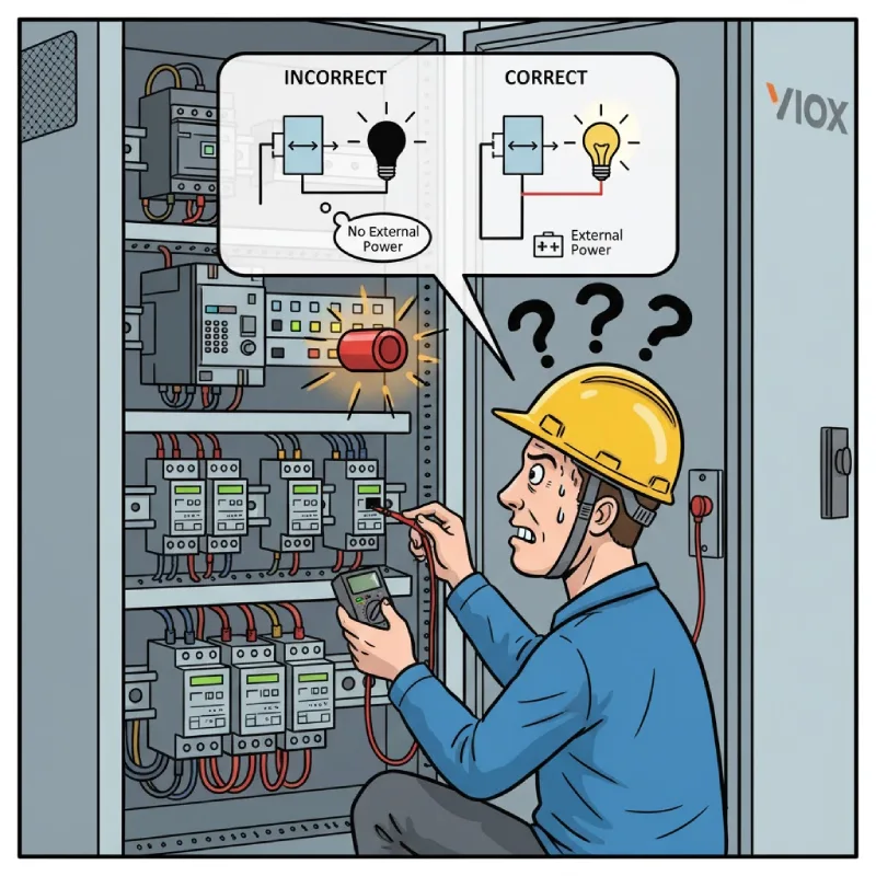
But when you energize the system, nothing happens. The PLC input LED stays dark even when you manually trigger the sensor. Or worse, you get random false triggers that create nuisance shutdowns costing thousands per hour. After burning three hours tracing circuits, you finally discover the culprit: you assumed a relay output would provide power to the load, but it’s a dry contact that requires an external source.
This single misunderstanding—wet contact versus dry contact—accounts for approximately 40% of control system commissioning delays and is the number one wiring error reported by field engineers. So how do you quickly identify which type of contact you’re dealing with, wire it correctly the first time, and avoid the voltage mismatches that sabotage otherwise perfect designs?
This guide provides the complete answer: a practical three-step method for identifying, wiring, and troubleshooting both contact types to eliminate costly rework and dangerous mistakes.
Why This Confusion Happens (And Why It Matters)
The root problem is that manufacturers operate under two completely different switching philosophies, and they rarely explain which one they’ve chosen.
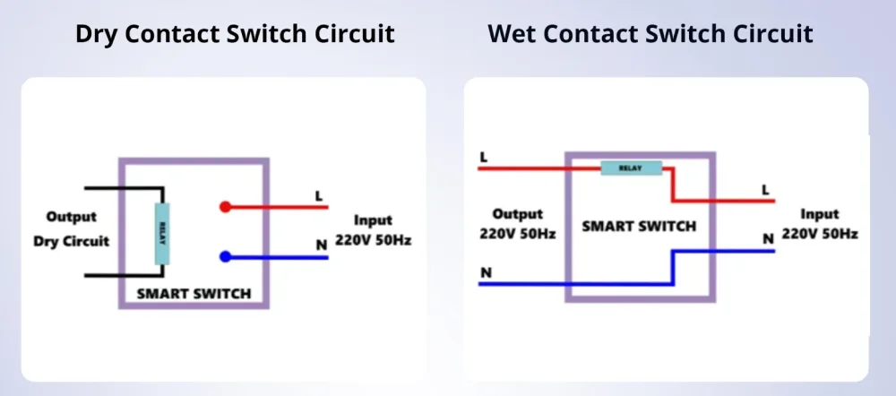
Some devices were designed for simplicity. Industrial sensors, for example, receive power on two wires and output that same power on a third wire when triggered—everything runs at the same voltage (typically 24V DC). This is a wet contact: power in equals power out, integrated into a single circuit.
Other devices were designed for flexibility and electrical isolation. Relays and PLC output modules act like a simple on/off switch: they control whether a separate power source reaches the load, but they don’t provide that power themselves. This is a dry contact: the switching action is electrically isolated from the control voltage.
Mix these up, and you’ll either have no power where you need it (connecting a load to a dry contact without external supply), or dangerous voltage feedback where you don’t expect it (backfeeding a wet contact into an input designed for dry switching).
Likmes ir augstas: improper contact usage doesn’t just cause downtime—it can damage expensive PLC I/O cards, create ground loops that generate signal noise, or violate electrical codes requiring galvanic isolation between control and power circuits.
Understanding the Core Difference: The Kitchen Light Analogy
Before diving into wiring, let’s establish a clear mental model using a familiar example.
A dry contact is like the light switch on your kitchen wall. Flip the switch, and the overhead light turns on—but the switch itself doesn’t generate any electricity. It simply controls whether power flows from your electrical panel to the light fixture. The switch is just a mechanical bridge in a circuit powered by something else (your slēdža panel). You could wire that switch to control 120V AC lighting, 24V DC LED strips, or a 480V motor starter—the switch doesn’t care, because it’s not providing the power.
A wet contact is like a battery-powered LED flashlight with a built-in switch. The battery (power source) and the switch are both inside the same housing. Press the button, and the integrated power immediately flows to the LED. You can’t use this switch to control a different voltage—it’s locked to whatever the battery provides (say, 3V DC). The power supply and switching mechanism are permanently married in one circuit.
In industrial terms:
- Dry contact = voltage-free, potential-free, passive switching (relejs contacts, PLC outputs)
- Wet contact = powered output, active switching (most proximity sensori, some smart switches)
Key Takeaway #1: A dry contact requires you to provide external power to the circuit it’s switching. A wet contact already has power built-in and supplies it directly to the load. Get this wrong, and your circuit is dead on arrival.
The 3-Step Method: Identify, Wire, and Troubleshoot
Step 1: Identify the Contact Type in 30 Seconds (The Wire Count Rule)
Most engineers waste time digging through datasheets when a simple wire count gives you the answer instantly.
The Quick Identification Method:
If the device has exactly 3 wires → It’s almost always a wet contact.
- Two wires power the device itself (e.g., +24V and 0V)
- The third wire is the switched output that provides that same voltage to your load
- Example: A PNP proximity sensor with Brown (+24V supply), Blue (0V supply), and Black (switched +24V output)
If the device has 4 or more wires → It’s usually a dry contact.
- Two wires power the device’s internal circuitry (coil voltage for relays)
- Two or more additional wires are isolated contact terminals (COM, NO, NC) that switch a completely separate circuit
- Example: A control relay with 24V AC coil terminals on one side and dry contact terminals (COM, NO, NC) on the other, rated for 250V AC switching
If the device has only 2 wires → It’s definitely a dry contact.
- These are the contact terminals themselves (typically COM and NO, or NO and NC)
- The switching mechanism is internal to a larger device (like a relay output built into a VFD or process controller)
- Example: A VFD with programmable relay terminals for fault signaling—just two screw terminals labeled “R1A” and “R1C”
Terminal Label Clues:
Dry contacts will have labels like:
- COM (Common), NO (Normally Open), NC (Normally Closed)
- C1, C2 (Contact 1, Contact 2) with no voltage marking
- “Voltage-free output” or “Potential-free relay” in the datasheet
Wet contacts will have labels like:
- OUT, OUTPUT, or LOAD with a voltage specification (e.g., “OUT 24V DC”)
- PNP or NPN (transistor output types, both are wet)
- “+24V Switched” or “Power Output”
Pro-Tip #1: PLC output modules are a trap for beginners. Even if the module spec says “24V DC Output,” this does NOT mean it provides 24V. It means it’s compatible with 24V circuits—but you must supply that voltage through a separate common (COM) terminal. All standard PLC outputs are dry contacts. The only exception is specialty “sourcing” modules explicitly labeled as providing output power, which are rare and expensive.
Step 2: Wire It Correctly—First Time, Every Time
Now that you’ve identified the contact type, here’s how to wire each configuration without error.
Dry Contact Wiring Architecture: The External Power Rule
A dry contact requires you to build a complete circuit using an external power source. Think of it as creating a loop: power source → dry contact → load → back to power source.
Standard Dry Contact Wiring for a PLC Input:
- Identify your external power supply (commonly a 24V DC panel supply)
- Connect the positive (+) side of the power supply to the “IN” or “COM” terminal of your PLC input module
- Run a wire from the PLC input terminal (e.g., I0.0) to one side of your dry contact (e.g., sensor’s COM terminal)
- Connect the other side of the contact (e.g., sensor’s NO terminal) back to the negative (−) side of the power supply (0V or ground)
- When the dry contact closes, it completes the circuit: +24V flows from COM → through the closed contact → through the PLC input → to 0V, turning on the input LED
Critical Error to Avoid: Never assume a dry contact output (like a relay NO terminal) will “give you” voltage when it closes. It won’t. You must provide the voltage yourself through proper external power wiring.
Standard Dry Contact Wiring for a PLC Output Driving a Load:
- Connect your external power supply positive (+) to the “OUT COM” terminal of your PLC output module
- Run a wire from the PLC output terminal (e.g., Q0.0) directly to one side of your load (e.g., solenoid valve’s positive terminal)
- Connect the other side of the load (solenoid’s negative terminal) back to the power supply negative (−)
- When the PLC activates output Q0.0, the dry contact closes, completing the circuit: +24V → load → 0V, energizing the solenoid
Key Takeaway #2: With dry contacts, YOU are the power supply’s circuit designer. The dry contact is just a switch in your loop. Always trace the complete path: power source → contact → load → return.
Wet Contact Wiring Architecture: Direct Connection
Wet contacts are simpler because the power is built-in. You’re just connecting the load to receive that integrated power when the contact switches.
Standard Wet Contact Wiring (PNP Sensor to PLC):
- Power the sensor using two wires: Brown to +24V, Blue to 0V
- Connect the sensor’s output wire (Black on a PNP sensor) directly to the PLC input terminal (e.g., I0.0)
- Connect the PLC input common to 0V (if not already internally grounded)
- When the sensor triggers, its internal transistor switches, and the +24V already present inside the sensor flows out the Black wire to the PLC input—no external power loop needed
Voltage Compatibility Warning: Because wet contacts have a fixed internal voltage (usually 10-30V DC), the load MUST be rated for that exact voltage. Connecting a 12V DC load to a 24V DC wet contact output will destroy the load. Always verify voltage specifications.
Pro-Tip #2: When interfacing wet contact sensors to PLCs, pay attention to sourcing vs. sinking logic. PNP sensors (sourcing) output +24V when triggered and work with sinking PLC inputs. NPN sensors (sinking) output 0V when triggered and work with sourcing PLC inputs. Mismatch these, and you’ll get inverted logic or no signal at all. Most modern PLCs use sinking inputs (compatible with PNP sensors), but always verify.
Step 3: Troubleshoot Like a Pro—Voltage Measurement Techniques
Even with correct identification and wiring, issues arise. Here’s how to diagnose them systematically.
Dry Contact Troubleshooting
Problem: PLC input won’t turn on, even with the sensor/contact triggered
Diagnostikas soļi:
- Measure voltage across the PLC input terminal and COM with the contact closed. You should read your supply voltage (e.g., 24V DC). If you read 0V, the external power isn’t reaching the input.
- Check continuity across the dry contact in the triggered state. With the circuit de-energized, you should measure near-zero ohms when closed. If you read infinite resistance, the contact is stuck open (mechanical failure or corrosion).
- Verify the external power supply is actually providing voltage. A tripped breaker or blown fuse on the 24V supply will kill all circuits using that source.
Pro-Tip #3: The most common dry contact wiring mistake? Forgetting to connect the load return path to 0V. Engineers wire the positive side correctly but leave the negative floating. Use a voltmeter to confirm the complete loop: you should measure 0V between the load’s negative terminal and the power supply’s 0V rail. Any voltage here means a broken return path.
Problem: Intermittent triggering, noise, or false signals
Root cause: Dry contacts physically separate control and power circuits, but long wire runs can pick up electromagnetic interference (EMI) from nearby motors or VFDs.
Risinājumi:
- Use twisted-pair shielded cable for dry contact wiring, with the shield grounded at the panel end only (not both ends—that creates a ground loop)
- Add a ferrite core to the cable near the PLC to suppress high-frequency noise
- If severe, install an optoisolator or signal conditioner between the dry contact and the PLC input to provide additional electrical isolation
Wet Contact Troubleshooting
Problem: Sensor output reads correct voltage, but the load doesn’t activate
Diagnostikas soļi:
- Measure the wet contact’s output current capability in the datasheet. Most sensor outputs are rated for only 100-200mA. If your load draws more (e.g., a large indicator light or relay coil), the sensor’s internal transistor is in current-limiting or has failed.
- Risinājums: Add an interposing relay. Use the wet contact sensor output to drive a small relay coil (50mA), and use that relay’s dry contacts to switch the higher-current load with external power.
Pro-Tip #4: Wet contact sensors have a “voltage drop” specification (typically 2-3V). This means when the sensor is triggered and outputting, you won’t measure the full supply voltage—you’ll measure 21-22V instead of 24V. This is normal and won’t affect most DC loads, but it can cause issues with sensitive electronics expecting a clean 24V. Factor this drop into your design.
Problem: Wet contact overheats or fails prematurely
Root cause: Exceeding the output’s current or voltage rating. Wet contacts have strict electrical limits because the switching element (usually a transistor) is embedded in the same compact housing as the sensor circuitry.
Risinājumi:
- Never exceed the rated output current (check datasheet for “Output Current” spec, usually 100-250mA for sensors)
- For higher loads, use the wet contact to trigger a relay or solid-state switch rated for the actual load current
- Ensure adequate heat dissipation—don’t mount sensors in enclosed, unventilated boxes if they’re switching near their current limit
Key Takeaway #3: Wet contacts sacrifice flexibility for simplicity. They’re perfect for low-power signaling (sensors to PLCs, status indicators), but they’re poor choices for directly driving high-current loads like motors, solenoids, or heaters. For those applications, use dry contact relays with appropriate external power supplies.
Application Selection Guide: When to Use Each Type
Choose Dry Contacts When:
- You need electrical isolation between control and load circuits (required by many safety standards like NFPA 79)
- Load voltage differs from control voltage (e.g., 24V DC PLC controlling a 120V AC solenoid)
- Long cable runs are involved, and you need noise immunity (dry contacts with proper shielding excel here)
- High-current loads require switching (use a dry contact relay rated for 10A, 20A, or higher)
- Multiple voltage systems coexist in one panel (dry contacts let you mix 24V DC sensors, 120V AC indicators, and 480V contactors)
Practical example: A PLC controlling an industrial oven. The PLC outputs are 24V DC dry contacts that drive 120V AC contactor coils, which in turn switch 480V three-phase power to heating elements. Each stage is electrically isolated for safety and code compliance.
Choose Wet Contacts When:
- Simplicity matters more than flexibility (residential/commercial HVAC controls, basic machinery)
- All devices operate at the same voltage (uniform 24V DC control system)
- Low-power signaling is the primary function (sensors communicating with PLCs or microcontrollers)
- Installation cost must be minimized (wet contacts require fewer power wires and less field wiring labor)
Practical example: A smart building system with dozens of occupancy sensors feeding a BACnet controller. All devices run on 24V DC, sensor outputs are 50mA max, and the simplified 3-wire connections (power, ground, signal) reduce installation time by 30% compared to dry contact wiring.
Standards, Safety, and Compliance Considerations
Electrical codes and safety standards often dictate which contact type you must use:
Dry Contact Requirements:
- IEC 60664-1 specifies minimum creepage and clearance distances for isolation between circuits—dry contacts must meet these spacing requirements
- UL 508A for industrial control panels requires isolation between Class 1 (line voltage) and Class 2 (low voltage) circuits—dry contacts provide this inherently
- NFPA 79 for industrial machinery mandates isolation between operator controls and power circuits in safety-critical applications
Wet Contact Applications:
- UL 60730 for automatic electrical controls (thermostats, HVAC controls) permits wet contacts in low-voltage, non-isolated circuits
- ISO 16750-2 for automotive electronics allows wet contact switching for in-vehicle 12V DC systems where isolation isn’t required
Pro-Tip #5: When in doubt, default to dry contacts for industrial applications. They provide the electrical isolation that most codes require, and the added wiring complexity is a minor trade-off for legal compliance and enhanced safety. Wet contacts are best reserved for pre-engineered systems where the manufacturer has already validated the design for code compliance.
Conclusion: Master the Distinction, Eliminate the Guesswork
By applying this three-step method—identify the contact type using wire count and terminal labels, wire it according to the correct architecture, and troubleshoot using systematic voltage measurements—you’ll eliminate the most common source of control system wiring failures.
Here’s what you’ve gained:
- 30-second identification using the wire count rule, saving hours of datasheet searches
- First-time-right wiring by understanding whether to provide external power (dry) or rely on integrated power (wet)
- Rapid troubleshooting using voltage measurement techniques that pinpoint open circuits, isolation failures, and current overloads
- Confident specification knowing when to choose dry contacts (for isolation, flexibility, high current) versus wet contacts (for simplicity, low power, uniform voltage)
The next time you energize a control panel and every input LED lights up perfectly on the first try, you’ll know it’s because you understood one fundamental principle: dry contacts switch separate circuits, wet contacts provide integrated power—and you wired accordingly.
Ready to put this knowledge into practice? Download our free Dry vs. Wet Contact Wiring Checklist (includes terminal identification flowchart, voltage measurement procedure, and troubleshooting decision tree) to keep this guide at your fingertips during commissioning. When your next project demands flawless control system integration, you’ll wire it right—the first time.
