
ເຄີຍສົງໄສບໍ່ວ່າເປັນຫຍັງເມື່ອໄຟຄຣິສມາດດັບໜ່ວຍໜຶ່ງ, ບາງຄັ້ງສາຍໄຟທັງໝົດກໍດັບໄປນຳ, ແຕ່ບາງຄັ້ງມີແຕ່ຫຼອດໄຟໜ່ວຍດຽວທີ່ຢຸດເຮັດວຽກ? ຄວາມລຶກລັບໃນຊີວິດປະຈຳວັນນີ້ສະແດງໃຫ້ເຫັນຢ່າງສົມບູນແບບກ່ຽວກັບພື້ນຖານ ຄວາມແຕກຕ່າງລະຫວ່າງວົງຈອນແບບຕໍ່ລຽນ ແລະ ວົງຈອນແບບຂະໜານ – ສອງວິທີພື້ນຖານທີ່ອົງປະກອບໄຟຟ້າສາມາດເຊື່ອມຕໍ່ກັນໄດ້ເຊິ່ງສົ່ງຜົນກະທົບຕໍ່ວິທີການໄຟຟ້າໄຫຼຜ່ານອຸປະກອນຂອງພວກເຮົາ.
ການເຂົ້າໃຈວົງຈອນແບບຕໍ່ລຽນທຽບກັບວົງຈອນແບບຂະໜານບໍ່ແມ່ນພຽງແຕ່ຄວາມຮູ້ທາງວິຊາການເທົ່ານັ້ນ. ແນວຄວາມຄິດເຫຼົ່ານີ້ກໍານົດທຸກສິ່ງທຸກຢ່າງຕັ້ງແຕ່ເຫດຜົນທີ່ເຕົ້າສຽບໄຟໃນເຮືອນຂອງທ່ານເຮັດວຽກເປັນອິດສະຫຼະຈົນເຖິງວິທີການລະບົບໄຟຟ້າຂອງລົດທ່ານເຮັດວຽກໄດ້ຢ່າງໜ້າເຊື່ອຖື. ບໍ່ວ່າທ່ານຈະເປັນນັກຮຽນທີ່ຮຽນຮູ້ກ່ຽວກັບເອເລັກໂຕຣນິກ, ເປັນຜູ້ມັກເຮັດໂຄງການໄຟຟ້າດ້ວຍຕົນເອງ, ຫຼືພຽງແຕ່ຢາກຮູ້ຢາກເຫັນກ່ຽວກັບວິທີການໄຟຟ້າເຮັດວຽກໃນຊີວິດປະຈໍາວັນຂອງທ່ານ, ການຮຽນຮູ້ແນວຄວາມຄິດເຫຼົ່ານີ້ຈະເຮັດໃຫ້ທ່ານມີຄວາມເຂົ້າໃຈທີ່ມີຄຸນຄ່າກ່ຽວກັບໂລກໄຟຟ້າອ້ອມຕົວທ່ານ.
ໃນຄູ່ມືທີ່ສົມບູນແບບນີ້, ພວກເຮົາຈະຄົ້ນຫາຄວາມແຕກຕ່າງທີ່ສໍາຄັນລະຫວ່າງວົງຈອນແບບຕໍ່ລຽນ ແລະ ວົງຈອນແບບຂະໜານ, ກວດສອບການນໍາໃຊ້ໃນໂລກຕົວຈິງ, ແລະໃຫ້ຄໍາແນະນໍາທີ່ເປັນປະໂຫຍດສໍາລັບການກໍານົດແລະແກ້ໄຂບັນຫາທັງສອງປະເພດ. ໃນຕອນທ້າຍ, ທ່ານຈະເຂົ້າໃຈບໍ່ພຽງແຕ່ວິທີການວົງຈອນເຫຼົ່ານີ້ເຮັດວຽກ, ແຕ່ເວລາໃດແລະເຫດຜົນທີ່ຈະໃຊ້ແຕ່ລະການຕັ້ງຄ່າ.
ຄໍາຕອບດ່ວນ: ຄວາມແຕກຕ່າງທີ່ສໍາຄັນລະຫວ່າງວົງຈອນແບບຕໍ່ລຽນ ແລະ ວົງຈອນແບບຂະໜານ
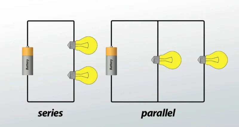
ວົງຈອນແບບຕໍ່ລຽນ: ອົງປະກອບຕ່າງໆເຊື່ອມຕໍ່ກັນແບບປາຍຫາປາຍໃນເສັ້ນທາງດຽວ. ກະແສໄຟຟ້າດຽວກັນໄຫຼຜ່ານອົງປະກອບທັງໝົດ, ແຕ່ແຮງດັນໄຟຟ້າແບ່ງອອກໃນແຕ່ລະອົງປະກອບໂດຍອີງໃສ່ຄວາມຕ້ານທານຂອງມັນ.
ວົງຈອນແບບຂະໜານ: ອົງປະກອບຕ່າງໆເຊື່ອມຕໍ່ກັນຂ້າມຈຸດເຊື່ອມຕໍ່ທົ່ວໄປ, ສ້າງເສັ້ນທາງຫຼາຍເສັ້ນທາງສໍາລັບກະແສໄຟຟ້າ. ແຕ່ລະອົງປະກອບໄດ້ຮັບແຮງດັນໄຟຟ້າດຽວກັນ, ແຕ່ກະແສໄຟຟ້າທັງໝົດແບ່ງອອກລະຫວ່າງສາຂາທີ່ແຕກຕ່າງກັນ.
ໂດຍລວມແລ້ວ: ໃນວົງຈອນແບບຕໍ່ລຽນ, ອົງປະກອບຕ່າງໆຂຶ້ນກັບກັນແລະກັນ (ຖ້າອົງປະກອບໜຶ່ງລົ້ມເຫຼວ, ທັງໝົດຈະຢຸດເຮັດວຽກ). ໃນວົງຈອນແບບຂະໜານ, ອົງປະກອບຕ່າງໆເຮັດວຽກເປັນອິດສະຫຼະ (ຖ້າອົງປະກອບໜຶ່ງລົ້ມເຫຼວ, ອົງປະກອບອື່ນໆສືບຕໍ່ເຮັດວຽກຕາມປົກກະຕິ).
ວົງຈອນແບບຕໍ່ລຽນແມ່ນຫຍັງ? [ຄໍານິຍາມ ແລະ ພື້ນຖານ]
ວົງຈອນແບບຕໍ່ລຽນເຮັດວຽກແນວໃດ
ກ ວົງຈອນແບບຕໍ່ລຽນ ເຊື່ອມຕໍ່ອົງປະກອບໄຟຟ້າແບບປາຍຫາປາຍ, ສ້າງເປັນເສັ້ນທາງຕໍ່ເນື່ອງດຽວສໍາລັບກະແສໄຟຟ້າທີ່ຈະໄຫຼ. ຄິດເຖິງມັນຄືກັບລົດທີ່ເດີນທາງໄປຕາມເສັ້ນທາງພູເຂົາເລນດຽວ – ລົດທຸກຄັນຕ້ອງເດີນຕາມເສັ້ນທາງດຽວກັນ, ແລະຖ້າມີສິ່ງກີດຂວາງຢູ່ບ່ອນໃດກໍຕາມ, ການສັນຈອນທັງໝົດຈະຢຸດ.
ໃນດ້ານໄຟຟ້າ, ນີ້ຫມາຍຄວາມວ່າ:
- ກະແສໄຟຟ້າໄຫຼຜ່ານແຕ່ລະອົງປະກອບເທື່ອລະອັນ
- ປະລິມານກະແສໄຟຟ້າດຽວກັນຜ່ານແຕ່ລະອົງປະກອບ
- ຖ້າອົງປະກອບໃດໜຶ່ງລົ້ມເຫຼວ ຫຼືຖືກຖອດອອກ, ວົງຈອນທັງໝົດຈະຢຸດເຮັດວຽກ
- ອົງປະກອບບໍ່ສາມາດຄວບຄຸມໄດ້ຢ່າງເປັນອິດສະຫຼະ
ຄຸນລັກສະນະທີ່ສໍາຄັນຂອງວົງຈອນແບບຕໍ່ລຽນ
ພຶດຕິກໍາຂອງກະແສໄຟຟ້າ: ຄຸນລັກສະນະທີ່ສໍາຄັນທີ່ສຸດຂອງວົງຈອນແບບຕໍ່ລຽນແມ່ນວ່າ ກະແສໄຟຟ້າຄົງທີ່ຕະຫຼອດວົງຈອນທັງໝົດ. ບໍ່ວ່າທ່ານຈະວັດແທກກະແສໄຟຟ້າກ່ອນອົງປະກອບທໍາອິດຫຼືຫຼັງຈາກອົງປະກອບສຸດທ້າຍ, ທ່ານຈະໄດ້ຮັບຄ່າທີ່ອ່ານໄດ້ຄືກັນ. ສິ່ງນີ້ເກີດຂຶ້ນເພາະວ່າມີພຽງແຕ່ເສັ້ນທາງດຽວສໍາລັບເອເລັກໂຕຣນິກທີ່ຈະເດີນຕາມ.
ການກະຈາຍແຮງດັນ: ບໍ່ເໝືອນກັບກະແສໄຟຟ້າ, ແຮງດັນໄຟຟ້າໃນວົງຈອນແບບຕໍ່ລຽນ ແບ່ງອອກໃນແຕ່ລະອົງປະກອບ. ຖ້າທ່ານມີແບັດເຕີຣີ 12 ໂວນທີ່ໃຫ້ພະລັງງານແກ່ຫຼອດໄຟສາມຫຼອດທີ່ຄືກັນໃນແບບຕໍ່ລຽນ, ແຕ່ລະຫຼອດຈະໄດ້ຮັບ 4 ໂວນ. ແຮງດັນໄຟຟ້າທີ່ຫຼຸດລົງໃນແຕ່ລະອົງປະກອບລວມກັນເທົ່າກັບແຮງດັນໄຟຟ້າຂອງແຫຼ່ງ – ເປັນຫຼັກການທີ່ສໍາຄັນສໍາລັບການອອກແບບວົງຈອນທີ່ເໝາະສົມ.
ຜົນກະທົບຂອງຄວາມຕ້ານທານ: ໃນວົງຈອນແບບຕໍ່ລຽນ, ຄວາມຕ້ານທານທັງໝົດເທົ່າກັບຜົນລວມຂອງຄວາມຕ້ານທານສ່ວນບຸກຄົນທັງໝົດ. ການເພີ່ມອົງປະກອບຫຼາຍຂຶ້ນຈະເພີ່ມຄວາມຕ້ານທານທັງໝົດ, ເຊິ່ງຊ່ວຍຫຼຸດຜ່ອນການໄຫຼຂອງກະແສໄຟຟ້າຕະຫຼອດວົງຈອນທັງໝົດ. ນີ້ແມ່ນເຫດຜົນທີ່ວ່າການເພີ່ມໄຟຫຼາຍຂຶ້ນໃສ່ວົງຈອນແບບຕໍ່ລຽນເຮັດໃຫ້ໄຟທັງໝົດມືດມົວລົງ.
ການດໍາເນີນງານແບບທັງໝົດ ຫຼື ບໍ່ມີຫຍັງເລີຍ: ບາງທີຄຸນລັກສະນະທີ່ສັງເກດເຫັນໄດ້ຫຼາຍທີ່ສຸດແມ່ນວ່າວົງຈອນແບບຕໍ່ລຽນເຮັດວຽກບົນພື້ນຖານແບບທັງໝົດ ຫຼື ບໍ່ມີຫຍັງເລີຍ. ເມື່ອທ່ານກົດສະວິດ, ອົງປະກອບທັງໝົດຈະເປີດພ້ອມກັນ. ເມື່ອອົງປະກອບໜຶ່ງລົ້ມເຫຼວ, ທຸກສິ່ງທຸກຢ່າງຈະຢຸດເຮັດວຽກ.
ຕົວຢ່າງວົງຈອນແບບຕໍ່ລຽນທີ່ທ່ານເຫັນທຸກໆມື້
ໄຟສາຍປະດັບຕົກແຕ່ງ (ແບບດັ້ງເດີມ): ສາຍໄຟຄຣິສມາດເກົ່າແກ່ໃຊ້ວົງຈອນແບບຕໍ່ລຽນ. ເມື່ອຫຼອດໄຟໜ່ວຍໜຶ່ງດັບ, ສາຍໄຟທັງໝົດຈະດັບໄປນຳເພາະວ່າວົງຈອນຖືກຕັດຂາດ. ໄຟສາຍປະດັບຕົກແຕ່ງທີ່ທັນສະໄໝມັກຈະມີກົນໄກຂ້າມຜ່ານ ຫຼືໃຊ້ວົງຈອນແບບຂະໜານເພື່ອຫຼີກເວັ້ນບັນຫານີ້.
ໄຟສາຍທີ່ມີແບັດເຕີຣີຫຼາຍໜ່ວຍ: ໄຟສາຍຫຼາຍອັນວາງແບັດເຕີຣີຊ້ອນກັນແບບປາຍຫາປາຍໃນແບບຕໍ່ລຽນເພື່ອເພີ່ມແຮງດັນໄຟຟ້າທັງໝົດ. ແບັດເຕີຣີ AA ສອງໜ່ວຍຂະໜາດ 1.5 ໂວນໃນແບບຕໍ່ລຽນໃຫ້ແຮງດັນໄຟຟ້າ 3 ໂວນເພື່ອໃຫ້ພະລັງງານແກ່ຫຼອດໄຟທີ່ສະຫວ່າງກວ່າທີ່ແບັດເຕີຣີໜ່ວຍດຽວສາມາດເຮັດໄດ້.
ລະບົບຄວາມປອດໄພຂອງລົດ: ເຊັນເຊີເຕືອນໄພຂອງລົດທີ່ຢູ່ອ້ອມປະຕູ ແລະປ່ອງຢ້ຽມມັກຈະຖືກສາຍໃນແບບຕໍ່ລຽນ. ຖ້າປະຕູ ຫຼືປ່ອງຢ້ຽມໃດໜຶ່ງຖືກເປີດ (ຕັດວົງຈອນ), ສັນຍານເຕືອນຈະກວດພົບວົງຈອນທີ່ເປີດ ແລະກະຕຸ້ນລະບົບເຕືອນ.
ສະວິດໄຟຟ້າ ແລະ ຟິວ: ອຸປະກອນຄວາມປອດໄພເຫຼົ່ານີ້ຖືກວາງໄວ້ໃນແບບຕໍ່ລຽນກັບວົງຈອນທີ່ພວກມັນປົກປ້ອງໂດຍເຈດຕະນາ. ເມື່ອຟິວຂາດ ຫຼືສະວິດເປີດ, ມັນຈະຕັດວົງຈອນແບບຕໍ່ລຽນ ແລະຢຸດການໄຫຼຂອງກະແສໄຟຟ້າເພື່ອປ້ອງກັນຄວາມເສຍຫາຍ ຫຼືໃຫ້ການຄວບຄຸມ.
ວົງຈອນແບບຂະໜານແມ່ນຫຍັງ? [ຄໍານິຍາມ ແລະ ພື້ນຖານ]
ວົງຈອນແບບຂະໜານເຮັດວຽກແນວໃດ
ກ ວົງຈອນແບບຂະໜານ ເຊື່ອມຕໍ່ອົງປະກອບຕ່າງໆຂ້າມຈຸດເຊື່ອມຕໍ່ທົ່ວໄປ, ສ້າງເສັ້ນທາງຫຼາຍເສັ້ນທາງສໍາລັບກະແສໄຟຟ້າທີ່ຈະໄຫຼ. ຈິນຕະນາການທາງຫຼວງທີ່ມີຫຼາຍເລນ – ຖ້າເລນໜຶ່ງຖືກກີດຂວາງ, ການສັນຈອນກໍຍັງສາມາດໄຫຼຜ່ານເລນອື່ນໆໄດ້. ແຕ່ລະເລນເຮັດວຽກເປັນອິດສະຫຼະ.
ໃນດ້ານໄຟຟ້າ, ນີ້ຫມາຍຄວາມວ່າ:
- ກະແສໄຟຟ້າມີຫຼາຍເສັ້ນທາງໃຫ້ເດີນທາງ
- ແຕ່ລະອົງປະກອບເຮັດວຽກເປັນອິດສະຫຼະ
- ອົງປະກອບສາມາດຄວບຄຸມແຍກຕ່າງຫາກໄດ້
- ຖ້າອົງປະກອບໜຶ່ງລົ້ມເຫຼວ, ອົງປະກອບອື່ນໆສືບຕໍ່ເຮັດວຽກຕາມປົກກະຕິ
ຄຸນລັກສະນະທີ່ສໍາຄັນຂອງວົງຈອນແບບຂະໜານ
ຄວາມສອດຄ່ອງຂອງແຮງດັນໄຟຟ້າ: ຄຸນສົມບັດທີ່ກໍານົດຂອງວົງຈອນແບບຂະໜານແມ່ນວ່າ ທຸກໆອົງປະກອບໄດ້ຮັບແຮງດັນໄຟຟ້າດຽວກັນ. ບໍ່ວ່າທ່ານຈະເຊື່ອມຕໍ່ອຸປະກອນໜຶ່ງ ຫຼືສິບອຸປະກອນໃນແບບຂະໜານ, ແຕ່ລະອຸປະກອນຈະໄດ້ຮັບແຮງດັນໄຟຟ້າເຕັມທີ່ຈາກແຫຼ່ງ. ນີ້ແມ່ນເຫດຜົນທີ່ວ່າເຕົ້າສຽບໄຟທັງໝົດໃນເຮືອນຂອງທ່ານໃຫ້ແຮງດັນໄຟຟ້າ 120 ໂວນດຽວກັນ (ໃນສະຫະລັດ) ໂດຍບໍ່ຄໍານຶງເຖິງຈໍານວນເຄື່ອງໃຊ້ທີ່ທ່ານສຽບ.
ການແບ່ງກະແສໄຟຟ້າ: ໃນຂະນະທີ່ແຮງດັນໄຟຟ້າຄົງທີ່, ກະແສໄຟຟ້າແບ່ງອອກລະຫວ່າງສາຂາທີ່ແຕກຕ່າງກັນ. ແຕ່ລະສາຂາດຶງເອົາພຽງແຕ່ກະແສໄຟຟ້າທີ່ມັນຕ້ອງການໂດຍອີງໃສ່ຄວາມຕ້ານທານຂອງມັນ. ກະແສໄຟຟ້າທັງໝົດຈາກແຫຼ່ງເທົ່າກັບຜົນລວມຂອງກະແສໄຟຟ້າທັງໝົດໃນສາຂາ – ຄືກັບນໍ້າທີ່ໄຫຼຜ່ານທໍ່ຫຼາຍທໍ່ທີ່ມີຂະໜາດແຕກຕ່າງກັນ.
ພຶດຕິກໍາຂອງຄວາມຕ້ານທານ: ກົງກັນຂ້າມກັບຄວາມເຂົ້າໃຈ, ການເພີ່ມອົງປະກອບຫຼາຍຂຶ້ນໃນແບບຂະໜານຕົວຈິງແລ້ວຈະຊ່ວຍຫຼຸດຜ່ອນຄວາມຕ້ານທານຂອງວົງຈອນທັງໝົດ. ເຫດການນີ້ເກີດຂຶ້ນເພາະວ່າທ່ານກໍາລັງສະໜອງເສັ້ນທາງເພີ່ມເຕີມສໍາລັບກະແສໄຟຟ້າທີ່ຈະໄຫຼ, ເຮັດໃຫ້ໄຟຟ້າສໍາເລັດວົງຈອນໄດ້ງ່າຍຂຶ້ນ. ມັນຄ້າຍຄືກັບການເພີ່ມຊ່ອງທາງເຊັກເອົາເພີ່ມເຕີມຢູ່ຮ້ານ – ຊ່ອງທາງເພີ່ມເຕີມໝາຍເຖິງເວລາລໍຖ້າໜ້ອຍລົງ.
ການດໍາເນີນງານທີ່ເປັນເອກະລາດ: ແຕ່ລະສາຂາຂອງວົງຈອນຂະໜານເຮັດວຽກເປັນເອກະລາດ. ທ່ານສາມາດເປີດແລະປິດອຸປະກອນໂດຍບໍ່ມີຜົນກະທົບຕໍ່ອຸປະກອນອື່ນໆ, ແລະຖ້າອຸປະກອນໜຶ່ງລົ້ມເຫລວ, ສ່ວນທີ່ເຫລືອຈະສືບຕໍ່ເຮັດວຽກຕາມປົກກະຕິ.
ຕົວຢ່າງວົງຈອນຂະໜານໃນເຮືອນຂອງທ່ານ
ເຕົ້າສຽບໄຟຟ້າໃນເຮືອນ: ທຸກໆເຕົ້າສຽບໃນເຮືອນຂອງທ່ານເຊື່ອມຕໍ່ແບບຂະໜານກັບແຜງໄຟຟ້າຫຼັກ. ນີ້ຊ່ວຍໃຫ້ທ່ານສາມາດສຽບເຄື່ອງໃຊ້ໄຟຟ້າໄດ້ຢ່າງເປັນອິດສະຫຼະ – ການເປີດຕູ້ເຢັນຂອງທ່ານບໍ່ມີຜົນກະທົບຕໍ່ຄອມພິວເຕີຂອງທ່ານ, ແລະຖ້າເຄື່ອງປີ້ງຂອງທ່ານເສຍ, ເຄື່ອງເຮັດກາເຟຂອງທ່ານຍັງເຮັດວຽກໄດ້.
ໄຟສ່ອງສະຫວ່າງລົດຍົນ: ໄຟໜ້າ, ໄຟທ້າຍ ແລະ ໄຟພາຍໃນລົດຂອງທ່ານຖືກສາຍແບບຂະໜານ. ທ່ານສາມາດຄວບຄຸມພວກມັນໄດ້ຢ່າງເປັນອິດສະຫຼະດ້ວຍສະວິດທີ່ແຕກຕ່າງກັນ, ແລະຖ້າຫລອດໄຟໜຶ່ງດັບ, ຫລອດໄຟອື່ນໆຈະສືບຕໍ່ໃຫ້ແສງສະຫວ່າງເພື່ອຄວາມປອດໄພ.
ອົງປະກອບຄອມພິວເຕີ: ພາຍໃນອຸປະກອນເອເລັກໂຕຣນິກ, ອົງປະກອບເຊັ່ນ: ຊິບໜ່ວຍຄວາມຈໍາ ແລະ ໂປຣເຊສເຊີຖືກເຊື່ອມຕໍ່ແບບຂະໜານເພື່ອຮັບປະກັນວ່າພວກມັນທັງໝົດໄດ້ຮັບແຮງດັນໄຟຟ້າທີ່ໝັ້ນຄົງສໍາລັບການດໍາເນີນງານທີ່ເຊື່ອຖືໄດ້.
ວົງຈອນໄຟສ່ອງສະຫວ່າງໃນເຮືອນ: ໄຟສ່ອງສະຫວ່າງໃນເຮືອນທີ່ທັນສະໄໝໃຊ້ວົງຈອນຂະໜານເພື່ອໃຫ້ທ່ານສາມາດຄວບຄຸມຫ້ອງຕ່າງໆໄດ້ຢ່າງເປັນອິດສະຫຼະ. ສະວິດໄຟແຕ່ລະອັນຄວບຄຸມສາຂາຂອງມັນເອງໂດຍບໍ່ມີຜົນກະທົບຕໍ່ໄຟໃນຫ້ອງອື່ນໆ.
ວົງຈອນຊຸດທຽບກັບວົງຈອນຂະໜານ: ການປຽບທຽບຂ້າງຄຽງ
| ລັກສະນະ | ວົງຈອນແບບຕໍ່ລຽນ | ວົງຈອນແບບຂະໜານ |
|---|---|---|
| ກະແສປັດຈຸບັນ | ຄືກັນຜ່ານອົງປະກອບທັງໝົດ | ແບ່ງລະຫວ່າງສາຂາ |
| ແຮງດັນ | ແບ່ງຂ້າມອົງປະກອບ | ຄືກັນຂ້າມອົງປະກອບທັງໝົດ |
| ຄວາມຕ້ານທານທັງໝົດ | ຜົນລວມຂອງຄວາມຕ້ານທານສ່ວນບຸກຄົນ | ໜ້ອຍກວ່າຄວາມຕ້ານທານສ່ວນບຸກຄົນທີ່ນ້ອຍທີ່ສຸດ |
| ການຄວບຄຸມອົງປະກອບ | ອົງປະກອບທັງໝົດຮ່ວມກັນ | ການຄວບຄຸມອົງປະກອບທີ່ເປັນເອກະລາດ |
| ຄວາມລົ້ມເຫຼວຂອງອົງປະກອບ | ວົງຈອນທັງໝົດລົ້ມເຫຼວ | ອົງປະກອບອື່ນໆສືບຕໍ່ເຮັດວຽກ |
| ໂຫຼດແຫຼ່ງພະລັງງານ | ເພີ່ມຂຶ້ນກັບອົງປະກອບເພີ່ມເຕີມ | ເພີ່ມຂຶ້ນກັບອົງປະກອບເພີ່ມເຕີມ |
| ຄວາມສັບສົນຂອງສາຍໄຟ | ງ່າຍດາຍ, ການເຊື່ອມຕໍ່ໜ້ອຍລົງ | ສັບສົນກວ່າ, ການເຊື່ອມຕໍ່ຫຼາຍກວ່າ |
| ຄ່າໃຊ້ຈ່າຍ | ໂດຍທົ່ວໄປຕ່ຳກວ່າ | ໂດຍທົ່ວໄປສູງກວ່າ |
| ຄວາມຫນ້າເຊື່ອຖື | ຕ່ຳກວ່າ (ຄວາມລົ້ມເຫຼວຂອງຈຸດດຽວ) | ສູງກວ່າ (ເສັ້ນທາງຊໍ້າຊ້ອນ) |
| ຄໍາຮ້ອງສະຫມັກ | ການຄວບຄຸມງ່າຍດາຍ, ການແບ່ງແຮງດັນ | ສາຍໄຟໃນເຮືອນ, ອຸປະກອນທີ່ເປັນເອກະລາດ |
ພຶດຕິກໍາແຮງດັນ: ເປັນຫຍັງມັນຈຶ່ງສໍາຄັນ
ໃນວົງຈອນຊຸດ: ແຮງດັນຕົກຂ້າມແຕ່ລະອົງປະກອບໂດຍອີງໃສ່ຄວາມຕ້ານທານຂອງມັນ. ການແບ່ງແຮງດັນນີ້ແມ່ນເປັນປະໂຫຍດເມື່ອທ່ານຕ້ອງການລະດັບແຮງດັນທີ່ແຕກຕ່າງກັນສໍາລັບອົງປະກອບທີ່ແຕກຕ່າງກັນ. ຕົວຢ່າງ, ຖ້າທ່ານຕ້ອງການໃຊ້ພະລັງງານອຸປະກອນ 6 ໂວນຈາກແບັດເຕີຣີ 12 ໂວນ, ທ່ານສາມາດເພີ່ມຕົວຕ້ານທານໃນຊຸດເພື່ອຫຼຸດລົງ 6 ໂວນພິເສດ.
ໃນວົງຈອນຂະໜານ: ທຸກໆອົງປະກອບໄດ້ຮັບແຮງດັນໄຟຟ້າເຕັມທີ່, ຮັບປະກັນການປະຕິບັດທີ່ສອດຄ່ອງ. ນີ້ແມ່ນສິ່ງຈໍາເປັນສໍາລັບອຸປະກອນທີ່ຕ້ອງການແຮງດັນໄຟຟ້າສະເພາະເພື່ອເຮັດວຽກຢ່າງຖືກຕ້ອງ. ເຄື່ອງສາກສະມາດໂຟນຂອງທ່ານຕ້ອງການແຮງດັນໄຟຟ້າທີ່ຖືກຕ້ອງ – ໜ້ອຍເກີນໄປແລະມັນຈະບໍ່ສາກໄຟ, ຫຼາຍເກີນໄປແລະມັນອາດຈະເສຍຫາຍ.
ຮູບແບບການໄຫຼຂອງກະແສໄຟຟ້າ
ການໄຫຼຂອງກະແສໄຟຟ້າຊຸດ: ກະແສໄຟຟ້າບໍ່ມີທາງເລືອກນອກຈາກການໄຫຼຜ່ານແຕ່ລະອົງປະກອບຕາມລໍາດັບ. ນີ້ເຮັດໃຫ້ການວັດແທກກະແສໄຟຟ້າງ່າຍດາຍ (ຄືກັນທຸກບ່ອນ) ແຕ່ຫມາຍຄວາມວ່າອົງປະກອບທີ່ອ່ອນແອທີ່ສຸດຈໍາກັດການປະຕິບັດຂອງວົງຈອນທັງໝົດ.
ການໄຫຼຂອງກະແສໄຟຟ້າຂະໜານ: ກະແສໄຟຟ້າແບ່ງອອກໂດຍອີງໃສ່ຄວາມຕ້ານທານຂອງແຕ່ລະສາຂາ, ປະຕິບັດຕາມເສັ້ນທາງຂອງຄວາມຕ້ານທານໜ້ອຍທີ່ສຸດ. ສາຂາທີ່ມີຄວາມຕ້ານທານຕ່ຳດຶງກະແສໄຟຟ້າຫຼາຍກວ່າ, ໃນຂະນະທີ່ສາຂາທີ່ມີຄວາມຕ້ານທານສູງດຶງກະແສໄຟຟ້າໜ້ອຍກວ່າ. ນີ້ຊ່ວຍໃຫ້ອຸປະກອນທີ່ມີຄວາມຕ້ອງການພະລັງງານທີ່ແຕກຕ່າງກັນສາມາດແບ່ງປັນວົງຈອນດຽວກັນໄດ້.
ການຄິດໄລ່ຄວາມຕ້ານທານເຮັດໃຫ້ງ່າຍດາຍ
ຄວາມຕ້ານທານຊຸດ: ພຽງແຕ່ເພີ່ມພວກມັນຂຶ້ນ
- ຄວາມຕ້ານທານທັງໝົດ = R₁ + R₂ + R₃ + …
- ຕົວຢ່າງ: 10Ω + 20Ω + 30Ω = 60Ω ທັງໝົດ
ຄວາມຕ້ານທານຂະໜານ: ໃຊ້ສູດປີ້ນກັນ
- 1/ຄວາມຕ້ານທານທັງໝົດ = 1/R₁ + 1/R₂ + 1/R₃ + …
- ຕົວຢ່າງ: ສອງຕົວຕ້ານທານ 10Ω ໃນຂະໜານ = 5Ω ທັງໝົດ
- ຄໍາແນະນໍາໄວ: ສໍາລັບຕົວຕ້ານທານທີ່ຄືກັນ, ໃຫ້ຫານດ້ວຍຈໍານວນຕົວຕ້ານທານ
ການນໍາໃຊ້ໃນໂລກທີ່ແທ້ຈິງ: ບ່ອນທີ່ປະເພດວົງຈອນແຕ່ລະອັນສ່ອງແສງ
ເປັນຫຍັງວົງຈອນຊຸດຈຶ່ງຖືກໃຊ້
ການນໍາໃຊ້ການຄວບຄຸມແຮງດັນ: ວົງຈອນຊຸດເກັ່ງເມື່ອທ່ານຕ້ອງການສ້າງລະດັບແຮງດັນສະເພາະ. ຊຸດແບັດເຕີຣີສໍາລັບເຄື່ອງມືໄຟຟ້າ ມັກຈະເຊື່ອມຕໍ່ເຊລໃນຊຸດເພື່ອບັນລຸແຮງດັນໄຟຟ້າທີ່ສູງຂຶ້ນ – ສີ່ເຊລລິທຽມ 3.7V ໃນຊຸດສ້າງຊຸດແບັດເຕີຣີ 14.8V.
ລະບົບຄວາມປອດໄພ ແລະ ຄວບຄຸມ: ວົງຈອນຕໍ່ລຽນມີຄຸນລັກສະນະປ້ອງກັນຄວາມຜິດພາດທີ່ດີເລີດ. ຖ້າເຊັນເຊີໃດໜຶ່ງໃນລະບົບຄວາມປອດໄພຂັດຂ້ອງ (ເຊັນເຊີປະຕູ, ເຊັນເຊີປ່ອງຢ້ຽມ, ເຄື່ອງກວດຈັບການເຄື່ອນໄຫວ), ວົງຈອນເປີດຈະແຈ້ງເຕືອນລະບົບທັນທີ. ການອອກແບບ “ປ້ອງກັນຄວາມຜິດພາດ” ນີ້ຮັບປະກັນວ່າບັນຫາຖືກກວດພົບຢ່າງໄວວາ.
ວິທີແກ້ໄຂທີ່ຄຸ້ມຄ່າ: ສໍາລັບການນໍາໃຊ້ງ່າຍໆທີ່ອົງປະກອບທັງໝົດຄວນເຮັດວຽກຮ່ວມກັນ, ວົງຈອນຕໍ່ລຽນຊ່ວຍຫຼຸດຜ່ອນຄ່າໃຊ້ຈ່າຍໃນການສາຍໄຟ ແລະ ອົງປະກອບ. ສະວິດອັນດຽວສາມາດຄວບຄຸມໄຟ ຫຼື ອຸປະກອນຫຼາຍອັນພ້ອມກັນໄດ້.
ການຈຳກັດກະແສໄຟຟ້າ: ຕົວຕ້ານທານຕໍ່ລຽນຖືກນໍາໃຊ້ທົ່ວໄປເພື່ອຈໍາກັດກະແສໄຟຟ້າໄປຫາອົງປະກອບທີ່ລະອຽດອ່ອນເຊັ່ນ: ໄຟ LED, ປົກປ້ອງພວກມັນຈາກຄວາມເສຍຫາຍໃນຂະນະທີ່ຮັບປະກັນການເຮັດວຽກທີ່ເໝາະສົມ.
ເຫດຜົນທີ່ວົງຈອນຂະໜານຄອບງໍາການສາຍໄຟໃນເຮືອນ
ການຄວບຄຸມອຸປະກອນແບບອິດສະຫຼະ: ການສາຍໄຟແບບຂະໜານຊ່ວຍໃຫ້ການເຮັດວຽກຂອງອຸປະກອນໄຟຟ້າເປັນອິດສະຫຼະ. ທ່ານສາມາດເປີດເຄື່ອງລ້າງຈານຂອງທ່ານໃນຂະນະທີ່ຄອມພິວເຕີຂອງທ່ານປິດຢູ່, ແລະບໍ່ມີອັນໃດອັນໜຶ່ງສົ່ງຜົນກະທົບຕໍ່ການເຮັດວຽກຂອງອີກອັນໜຶ່ງ.
ປະສິດທິພາບຂອງອຸປະກອນທີ່ສອດຄ່ອງ: ທຸກໆອຸປະກອນໄດ້ຮັບແຮງດັນໄຟຟ້າເຕັມທີ່, ຮັບປະກັນປະສິດທິພາບທີ່ດີທີ່ສຸດ. ຕູ້ເຢັນຂອງທ່ານໄດ້ຮັບ 120V ດຽວກັນບໍ່ວ່າທ່ານຈະເປີດເຄື່ອງປັບອາກາດຫຼືບໍ່.
ຄວາມຫນ້າເຊື່ອຖືຂອງລະບົບ: ຖ້າອຸປະກອນໜຶ່ງຂັດຂ້ອງ, ອຸປະກອນອື່ນໆຈະສືບຕໍ່ເຮັດວຽກ. ເມື່ອຫລອດໄຟດັບ, ໄຟອື່ນໆຂອງທ່ານຍັງເປີດຢູ່. ການຊໍ້າຊ້ອນນີ້ແມ່ນສໍາຄັນສໍາລັບລະບົບທີ່ສໍາຄັນເຊັ່ນ: ໄຟສຸກເສີນແລະອຸປະກອນຄວາມປອດໄພ.
ຄວາມສາມາດໃນການຂະຫຍາຍ: ທ່ານສາມາດເພີ່ມອຸປະກອນເພີ່ມເຕີມໃສ່ວົງຈອນຂະໜານໄດ້ໂດຍບໍ່ມີຜົນກະທົບຢ່າງຫຼວງຫຼາຍຕໍ່ອຸປະກອນທີ່ມີຢູ່ (ພາຍໃນຂອບເຂດຈໍາກັດຄວາມສາມາດຂອງວົງຈອນ). ຄວາມຍືດຫຍຸ່ນນີ້ເຮັດໃຫ້ການສາຍໄຟແບບຂະໜານເໝາະສົມສຳລັບລະບົບທີ່ສາມາດຂະຫຍາຍໄດ້.
ການປະສົມປະສານແບບລຽນ-ຂະໜານໃນລະບົບທີ່ສັບສົນ
ລະບົບໄຟຟ້າໃນໂລກຕົວຈິງສ່ວນໃຫຍ່ລວມເອົາທັງອົງປະກອບແບບລຽນ ແລະ ຂະໜານ ເພື່ອເພີ່ມປະສິດທິພາບ, ຄ່າໃຊ້ຈ່າຍ ແລະ ຄວາມໜ້າເຊື່ອຖື:
Automotive Electrical Systems: ລົດໃຊ້ວົງຈອນຕໍ່ລຽນສໍາລັບການຄວບຄຸມບາງຢ່າງ (ເຊັ່ນ: ລະບົບເຊັນເຊີ) ໃນຂະນະທີ່ໃຊ້ວົງຈອນຂະໜານສໍາລັບໄຟແລະອຸປະກອນເສີມ. ວົງຈອນສະຕາດເຕີອາດມີອົງປະກອບຕໍ່ລຽນເພື່ອຄວາມປອດໄພ, ໃນຂະນະທີ່ລະບົບໄຟໃຊ້ວົງຈອນຂະໜານສໍາລັບການເຮັດວຽກທີ່ເປັນອິດສະຫຼະ.
ເຄື່ອງໃຊ້ໄຟຟ້າ: ຊຸດແບັດເຕີຣີຂອງແລັບທັອບຂອງທ່ານອາດມີເຊລທີ່ເຊື່ອມຕໍ່ທັງແບບລຽນ (ສໍາລັບແຮງດັນໄຟຟ້າ) ແລະ ຂະໜານ (ສໍາລັບຄວາມຈຸ). ວົງຈອນສາກໄຟໃຊ້ອົງປະກອບຕໍ່ລຽນສໍາລັບການຄວບຄຸມແຮງດັນໄຟຟ້າ ແລະ ອົງປະກອບຂະໜານສໍາລັບການຊໍ້າຊ້ອນ.
ແຜງໄຟຟ້າໃນເຮືອນ: ເຄື່ອງຕັດວົງຈອນແມ່ນຕໍ່ລຽນກັບວົງຈອນຂອງພວກເຂົາ (ເພື່ອຄວາມປອດໄພ), ໃນຂະນະທີ່ເຕົ້າສຽບແຕ່ລະອັນໃນແຕ່ລະວົງຈອນແມ່ນເຊື່ອມຕໍ່ແບບຂະໜານ (ສໍາລັບການເຮັດວຽກທີ່ເປັນອິດສະຫຼະ).
ວິທີການກໍານົດວົງຈອນຕໍ່ລຽນທຽບກັບວົງຈອນຂະໜານ [ຄູ່ມືການປະຕິບັດ]
ວິທີການກໍານົດສາຍຕາ
ຕິດຕາມເສັ້ນທາງກະແສໄຟຟ້າ: ວິທີການທີ່ເຊື່ອຖືໄດ້ຫຼາຍທີ່ສຸດແມ່ນການຕິດຕາມເສັ້ນທາງທີ່ກະແສໄຟຟ້າຕ້ອງຜ່ານ:
- ຕໍ່ລຽນ: ມີພຽງເສັ້ນທາງດຽວທີ່ເປັນໄປໄດ້ຈາກຂົ້ວບວກໄປຫາຂົ້ວລົບ
- ຂະໜານ: ມີຫຼາຍເສັ້ນທາງລະຫວ່າງຈຸດເຊື່ອມຕໍ່ສອງຈຸດດຽວກັນ
ນັບຈຸດເຊື່ອມຕໍ່:
- ຕໍ່ລຽນ: ແຕ່ລະອົງປະກອບເຊື່ອມຕໍ່ກັບອີກສອງອົງປະກອບ (ຍົກເວັ້ນອົງປະກອບທໍາອິດແລະອົງປະກອບສຸດທ້າຍ)
- ຂະໜານ: ອົງປະກອບແບ່ງປັນຈຸດເຊື່ອມຕໍ່ທົ່ວໄປ, ສ້າງຈຸດເຊື່ອມຕໍ່ “T” ຫຼື “Y”
ຊອກຫາການແຕກງ່າ:
- ຕໍ່ລຽນ: ອົງປະກອບປະກອບເປັນຕ່ອງໂສ້ອັນດຽວ
- ຂະໜານ: ເສັ້ນທາງກະແສໄຟຟ້າແຕກງ່າ ແລະ ເຊື່ອມຕໍ່ຄືນໃໝ່
ພຶດຕິກໍາຂອງສະວິດ:
- ຕໍ່ລຽນ: ສະວິດອັນດຽວຄວບຄຸມອົງປະກອບທັງໝົດ
- ຂະໜານ: ແຕ່ລະງ່າສາມາດມີສະວິດທີ່ເປັນອິດສະຫຼະ
ການທົດສອບດ້ວຍມັລຕິມິເຕີ
ວິທີການທົດສອບແຮງດັນໄຟຟ້າ:
- ການກໍານົດວົງຈອນຕໍ່ລຽນ: ວັດແທກແຮງດັນໄຟຟ້າໃນແຕ່ລະອົງປະກອບ. ໃນວົງຈອນຕໍ່ລຽນ, ແຮງດັນໄຟຟ້າຈະເພີ່ມຂຶ້ນເປັນແຮງດັນໄຟຟ້າຂອງແຫຼ່ງ.
- ການກໍານົດວົງຈອນຂະໜານ: ວັດແທກແຮງດັນໄຟຟ້າໃນແຕ່ລະອົງປະກອບ. ໃນວົງຈອນຂະໜານ, ອົງປະກອບທັງໝົດສະແດງແຮງດັນໄຟຟ້າດຽວກັນ.
ວິທີການທົດສອບກະແສໄຟຟ້າ:
- ການກໍານົດວົງຈອນຕໍ່ລຽນ: ການວັດແທກກະແສໄຟຟ້າຈະຄືກັນໃນທຸກຈຸດໃນວົງຈອນ.
- ການກໍານົດວົງຈອນຂະໜານ: ການວັດແທກກະແສໄຟຟ້າຈະແຕກຕ່າງກັນລະຫວ່າງງ່າແຕ່ລວມກັນເປັນກະແສໄຟຟ້າທັງໝົດ.
ວິທີການທົດສອບຄວາມຕ້ານທານ:
- ປິດໄຟວົງຈອນໃຫ້ໝົດ
- ຕໍ່ລຽນ: ຄວາມຕ້ານທານທັງໝົດເທົ່າກັບຜົນລວມຂອງຄວາມຕ້ານທານຂອງອົງປະກອບແຕ່ລະອັນ
- ຂະໜານ: ຄວາມຕ້ານທານທັງໝົດໜ້ອຍກວ່າຄວາມຕ້ານທານຂອງອົງປະກອບແຕ່ລະອັນທີ່ນ້ອຍທີ່ສຸດ
ຂໍ້ຄວນລະວັງຄວາມປອດໄພ:
- ປິດໄຟສະເໝີກ່ອນທີ່ຈະເຊື່ອມຕໍ່ເຄື່ອງວັດແທກສໍາລັບການວັດແທກກະແສໄຟຟ້າ
- ໃຊ້ລະດັບແຮງດັນໄຟຟ້າ ແລະ ກະແສໄຟຟ້າທີ່ເໝາະສົມ
- ຢ່າວັດແທກຄວາມຕ້ານທານໃນວົງຈອນທີ່ມີໄຟ
- ກວດເບິ່ງການເຊື່ອມຕໍ່ສອງຄັ້ງກ່ອນທີ່ຈະໃຊ້ພະລັງງານ
ສະຖານະການແກ້ໄຂບັນຫາທົ່ວໄປ
ເມື່ອອົງປະກອບໜຶ່ງສົ່ງຜົນກະທົບຕໍ່ອົງປະກອບອື່ນໆ (ຊີ້ບອກວົງຈອນຕໍ່ລຽນ):
- ຫລອດໄຟໜຶ່ງດັບ, ຫລອດໄຟທັງໝົດດັບ
- ອຸປະກອນໜຶ່ງຂັດຂ້ອງ, ວົງຈອນທັງໝົດຢຸດເຮັດວຽກ
- ການເພີ່ມອຸປະກອນເພີ່ມເຕີມເຮັດໃຫ້ອຸປະກອນທັງໝົດມືດມົວ ຫຼື ຊ້າລົງ
ເມື່ອອົງປະກອບເຮັດວຽກເປັນອິດສະຫຼະ (ຊີ້ບອກວົງຈອນຂະໜານ):
- ອຸປະກອນແຕ່ລະອັນສາມາດຄວບຄຸມແຍກຕ່າງຫາກໄດ້
- ການຂັດຂ້ອງຂອງອຸປະກອນໜຶ່ງບໍ່ມີຜົນກະທົບຕໍ່ອຸປະກອນອື່ນໆ
- ແຕ່ລະອຸປະກອນຮັກສາປະສິດທິພາບທີ່ສອດຄ່ອງໂດຍບໍ່ຄໍານຶງເຖິງອຸປະກອນອື່ນໆ
ການກໍານົດວົງຈອນປະສົມ:
- ບາງອົງປະກອບເຮັດວຽກເປັນອິດສະຫຼະ (ສ່ວນຂະໜານ)
- ບາງອົງປະກອບສົ່ງຜົນກະທົບຕໍ່ກັນ (ສ່ວນຕໍ່ລຽນ)
- ຕ້ອງການການວິເຄາະຢ່າງລະອຽດຂອງແຕ່ລະພາກສ່ວນວົງຈອນ
ການແບ່ງປັນຂໍ້ດີ ແລະ ຂໍ້ເສຍ
ຂໍ້ດີ ແລະ ຂໍ້ເສຍຂອງວົງຈອນແບບຕໍ່ລຽນ
ຂໍ້ດີ:
- ຄວາມລຽບງ່າຍ: ຕ້ອງການສາຍໄຟ ແລະ ການເຊື່ອມຕໍ່ໜ້ອຍທີ່ສຸດ
- ປະຢັດຄ່າໃຊ້ຈ່າຍ: ມີສ່ວນປະກອບໜ້ອຍກວ່າ ແລະ ການຕິດຕັ້ງງ່າຍກວ່າ
- ການຄວບຄຸມແຮງດັນໄຟຟ້າທີ່ຊັດເຈນ: ສ້າງແຮງດັນໄຟຟ້າທີ່ຕ້ອງການໄດ້ງ່າຍ
- ກະແສໄຟຟ້າສະໝໍ່າສະເໝີ: ກະແສໄຟຟ້າຜ່ານທຸກສ່ວນປະກອບເທົ່າກັນ ເຮັດໃຫ້ການຄຳນວນງ່າຍຂຶ້ນ
- ການວັດແທກກະແສໄຟຟ້າໄດ້ງ່າຍ: ກະແສໄຟຟ້າຄືກັນທົ່ວວົງຈອນ
ຂໍ້ເສຍ:
- ຈຸດບົກຜ່ອງດຽວ: ຄວາມລົ້ມເຫຼວຂອງສ່ວນປະກອບໜຶ່ງຢຸດວົງຈອນທັງໝົດ
- ແຮງດັນໄຟຟ້າຕົກ: ການເພີ່ມສ່ວນປະກອບຫຼຸດແຮງດັນໄຟຟ້າໃຫ້ແຕ່ລະອຸປະກອນ
- ບໍ່ມີການຄວບຄຸມເອກະລາດ: ບໍ່ສາມາດຄວບຄຸມສ່ວນປະກອບແຕ່ລະອັນໄດ້
- ຄວາມຍືດຫຍຸ່ນຈຳກັດ: ຍາກທີ່ຈະດັດແກ້ ຫຼື ຂະຫຍາຍ
- ຂໍ້ຈຳກັດຂອງກະແສໄຟຟ້າ: ທຸກສ່ວນປະກອບຕ້ອງຮອງຮັບກະແສໄຟຟ້າດຽວກັນ
ຂໍ້ດີ ແລະ ຂໍ້ເສຍຂອງວົງຈອນແບບຂະໜານ
ຂໍ້ດີ:
- ການດໍາເນີນງານທີ່ເປັນເອກະລາດ: ແຕ່ລະອຸປະກອນສາມາດຄວບຄຸມແຍກຕ່າງຫາກໄດ້
- ຄວາມຫນ້າເຊື່ອຖື: ຄວາມລົ້ມເຫຼວຂອງສ່ວນປະກອບບໍ່ມີຜົນກະທົບຕໍ່ອຸປະກອນອື່ນໆ
- ແຮງດັນໄຟຟ້າຄົງທີ່: ແຕ່ລະອຸປະກອນໄດ້ຮັບແຮງດັນໄຟຟ້າເຕັມທີ່ຈາກແຫຼ່ງ
- ສາມາດຂະຫຍາຍໄດ້: ເພີ່ມອຸປະກອນໄດ້ງ່າຍ (ພາຍໃນຂອບເຂດຈຳກັດ)
- ການຄວບຄຸມທີ່ຍືດຫຍຸ່ນ: ສາມາດໃຊ້ສະວິດແຕ່ລະອັນສຳລັບແຕ່ລະສາຂາໄດ້
ຂໍ້ເສຍ:
- ຄວາມສັບສົນ: ຕ້ອງການສາຍໄຟ ແລະ ການເຊື່ອມຕໍ່ຫຼາຍກວ່າ
- ຄ່າໃຊ້ຈ່າຍສູງກວ່າ: ວັດສະດຸ ແລະ ແຮງງານຫຼາຍກວ່າສຳລັບການຕິດຕັ້ງ
- ການເພີ່ມກະແສໄຟຟ້າ: ກະແສໄຟຟ້າທັງໝົດເພີ່ມຂຶ້ນກັບແຕ່ລະອຸປະກອນທີ່ເພີ່ມເຂົ້າມາ
- ການດຸ່ນດ່ຽງພາລະ: ຕ້ອງຮັບປະກັນວ່າກະແສໄຟຟ້າທັງໝົດບໍ່ເກີນຄວາມສາມາດຂອງແຫຼ່ງ
- ຄວາມສັບສົນໃນການແກ້ໄຂບັນຫາ: ມີວົງຈອນຫຼາຍກວ່າທີ່ຈະກວດສອບ ແລະ ຮັກສາ
ຄວາມຜິດພາດທົ່ວໄປ ແລະ ຄຳແນະນຳໃນການແກ້ໄຂບັນຫາ
ຄວາມຜິດພາດໃນການອອກແບບທີ່ຄວນຫຼີກລ່ຽງ
ຄວາມສັບສົນກ່ຽວກັບແຮງດັນໄຟຟ້າ ແລະ ກະແສໄຟຟ້າ:
- ຄວາມຜິດພາດ: ສົມມຸດວ່າທຸກສ່ວນປະກອບຕ້ອງການກະແສໄຟຟ້າດຽວກັນໃນວົງຈອນຂະໜານ
- ການແກ້ໄຂ: ຈົ່ງຈື່ໄວ້ວ່າກະແສໄຟຟ້າແບ່ງອອກ ໃນຂະນະທີ່ແຮງດັນໄຟຟ້າຄົງທີ່
ການລະເລີຍການຈັດອັນດັບສ່ວນປະກອບ:
- ຄວາມຜິດພາດ: ການໃຊ້ສ່ວນປະກອບທີ່ຖືກຈັດອັນດັບສຳລັບກະແສໄຟຟ້າທີ່ແຕກຕ່າງກັນໃນວົງຈອນຕໍ່ລຽນ
- ການແກ້ໄຂ: ຮັບປະກັນວ່າສ່ວນປະກອບຕໍ່ລຽນທັງໝົດສາມາດຮອງຮັບກະແສໄຟຟ້າຂອງວົງຈອນໄດ້
ຂໍ້ຜິດພາດຂອງວົງຈອນຄວາມປອດໄພ:
- ຄວາມຜິດພາດ: ການວາງອຸປະກອນຄວາມປອດໄພ (ຟິວ, ເບຣກເກີ) ແບບຂະໜານແທນທີ່ຈະເປັນແບບຕໍ່ລຽນ
- ການແກ້ໄຂ: ອຸປະກອນຄວາມປອດໄພຕ້ອງຢູ່ໃນແບບຕໍ່ລຽນເພື່ອຕັດກະແສໄຟຟ້າ
ຂໍ້ຜິດພາດໃນການຄຳນວນພະລັງງານ:
- ຄວາມຜິດພາດ: ປະເມີນຄ່າການໃຊ້ພະລັງງານທັງໝົດຕໍ່າເກີນໄປໃນວົງຈອນຂະໜານ
- ການແກ້ໄຂ: ຄຳນວນພະລັງງານສຳລັບແຕ່ລະສາຂາແຍກຕ່າງຫາກ, ຈາກນັ້ນລວມກັນເພື່ອໃຫ້ໄດ້ຄ່າທັງໝົດ
ການແກ້ໄຂບັນຫາວົງຈອນຕໍ່ລຽນ
ສໍາເລັດຄວາມລົ້ມເຫຼວຂອງວົງຈອນ:
- ກວດເບິ່ງວົງຈອນເປີດ (ການເຊື່ອມຕໍ່ທີ່ຂາດ, ຟິວຂາດ)
- ທົດສອບແຕ່ລະສ່ວນປະກອບແຍກຕ່າງຫາກສຳລັບການຕໍ່ເນື່ອງ
- ກວດສອບແຮງດັນໄຟຟ້າຂອງແຫຼ່ງພະລັງງານ ແລະ ຄວາມສາມາດຂອງກະແສໄຟຟ້າ
- ຊອກຫາການເຊື່ອມຕໍ່ທີ່ກັດກ່ອນ ຫຼື ຫຼວມ
ບັນຫາການເຮັດວຽກທີ່ຫຼຸດລົງ:
- ວັດແທກແຮງດັນໄຟຟ້າທີ່ຕົກລົງໃນແຕ່ລະສ່ວນປະກອບ
- ກວດເບິ່ງການເຊື່ອມຕໍ່ທີ່ມີຄວາມຕ້ານທານສູງ
- ກວດສອບວ່າສະເພາະຂອງສ່ວນປະກອບກົງກັບຄວາມຕ້ອງການຂອງວົງຈອນ
- ທົດສອບການປ່ຽນແປງຂອງຄວາມຕ້ານທານທີ່ກ່ຽວຂ້ອງກັບອຸນຫະພູມ
ການດໍາເນີນງານແບບບໍ່ຢຸດຢັ້ງ:
- ກວດສອບການເຊື່ອມຕໍ່ທີ່ວ່າງທີ່ເຮັດໃຫ້ເກີດການຕິດຕໍ່ບໍ່ສະໝໍ່າສະເໝີ
- ທົດສອບອົງປະກອບພາຍໃຕ້ສະພາບອຸນຫະພູມທີ່ແຕກຕ່າງກັນ
- ກວດສອບຄວາມໜ້າເຊື່ອຖືຂອງສະວິດ ແລະຕົວເຊື່ອມຕໍ່
- ຊອກຫາບັນຫາການເຊື່ອມຕໍ່ທີ່ເກີດຈາກການສັ່ນສະເທືອນ
ການແກ້ໄຂບັນຫາວົງຈອນຂະໜານ
ຄວາມລົ້ມເຫຼວຂອງສາຂາແຕ່ລະອັນ:
- ແຍກສາຂາທີ່ມີບັນຫາໂດຍການທົດສອບແຕ່ລະອັນແຍກຕ່າງຫາກ
- ກວດສອບວົງຈອນເປີດໃນສາຂາທີ່ລົ້ມເຫຼວເທົ່ານັ້ນ
- ກວດສອບສະວິດ ແລະການເຊື່ອມຕໍ່ສະເພາະສາຂາ
- ທົດສອບການເຮັດວຽກຂອງອົງປະກອບແຕ່ລະອັນ
ບັນຫາການໂຫຼດທີ່ບໍ່ສົມດຸນ:
- ວັດແທກກະແສໄຟຟ້າໃນແຕ່ລະສາຂາເພື່ອກໍານົດຄວາມບໍ່ສົມດຸນ
- ກວດສອບອົງປະກອບທີ່ດຶງກະແສໄຟຟ້າຫຼາຍເກີນໄປ
- ກວດສອບແຮງດັນໄຟຟ້າທີ່ເໝາະສົມໃນແຕ່ລະຈຸດເຊື່ອມຕໍ່ສາຂາ
- ຊອກຫາຄວາມແຕກຕ່າງຂອງຄວາມຕ້ານທານລະຫວ່າງເສັ້ນທາງຂະໜານ
ບັນຫາວົງຈອນເກີນກຳນົດ:
- ຄິດໄລ່ການດຶງກະແສໄຟຟ້າທັງໝົດ ແລະປຽບທຽບກັບຄວາມສາມາດຂອງແຫຼ່ງ
- ກວດສອບຄວາມຮ້ອນເກີນໄປໃນສາຍໄຟ ແລະການເຊື່ອມຕໍ່
- ກວດສອບອຸປະກອນປ້ອງກັນວົງຈອນຖືກຂະໜາດຢ່າງຖືກຕ້ອງ
- ພິຈາລະນາການແຈກຢາຍການໂຫຼດຄືນໃໝ່ໃນທົ່ວວົງຈອນຫຼາຍອັນ
ທ່ານຄວນເລືອກປະເພດວົງຈອນໃດ?
ປັດໄຈການຕັດສິນໃຈ
ຄວາມຕ້ອງການຄວບຄຸມ:
- ເລືອກ ອະນຸກົມ ເມື່ອອົງປະກອບທັງໝົດຄວນເຮັດວຽກຮ່ວມກັນ
- ເລືອກ ຂະໜານ ເມື່ອຕ້ອງການການຄວບຄຸມທີ່ເປັນເອກະລາດ
ຄວາມຕ້ອງການຄວາມໜ້າເຊື່ອຖື:
- ເລືອກ ອະນຸກົມ ສໍາລັບຄໍາຮ້ອງສະຫມັກທີ່ງ່າຍດາຍ, ປະຫຍັດຄ່າໃຊ້ຈ່າຍທີ່ການດໍາເນີນງານພ້ອມກັນເປັນທີ່ຍອມຮັບ
- ເລືອກ ຂະໜານ ສໍາລັບຄໍາຮ້ອງສະຫມັກທີ່ສໍາຄັນທີ່ຄວາມເປັນເອກະລາດຂອງອົງປະກອບແມ່ນສໍາຄັນ
Voltage Requirements:
- ເລືອກ ອະນຸກົມ ເມື່ອທ່ານຕ້ອງການແບ່ງແຮງດັນໄຟຟ້າ ຫຼືສ້າງແຮງດັນໄຟຟ້າທີ່ສູງຂຶ້ນ
- ເລືອກ ຂະໜານ ເມື່ອອົງປະກອບທັງໝົດຕ້ອງການແຮງດັນໄຟຟ້າດຽວກັນ
ຂໍ້ຄວນພິຈາລະນາກ່ຽວກັບກະແສໄຟຟ້າ:
- ເລືອກ ອະນຸກົມ ເມື່ອການຈຳກັດກະແສໄຟຟ້າເປັນປະໂຫຍດ
- ເລືອກ ຂະໜານ ເມື່ອອົງປະກອບມີຄວາມຕ້ອງການກະແສໄຟຟ້າທີ່ແຕກຕ່າງກັນ
ແຜນການຂະຫຍາຍ:
- ເລືອກ ອະນຸກົມ ສໍາລັບການຕິດຕັ້ງທີ່ງ່າຍດາຍ, ຄົງທີ່
- ເລືອກ ຂະໜານ ສໍາລັບລະບົບທີ່ອາດຈະຕ້ອງການການຂະຫຍາຍໃນອະນາຄົດ
ຄຳແນະນຳສະເພາະແອັບພລິເຄຊັນ
ໂຄງການ DIY ບ້ານ:
- ໄຟສ່ອງແສງ: ໃຊວົງຈອນຂະໜານສຳລັບໄຟຫ້ອງ (ຄວບຄຸມເອກະລາດ)
- ໄຟຕົກແຕ່ງ: ອະນຸກົມອາດຈະເຮັດວຽກສໍາລັບຄໍາຮ້ອງສະຫມັກທີ່ງ່າຍດາຍທີ່ຕ້ອງການການດໍາເນີນງານພ້ອມກັນ
- ປລັກສຽບໄຟ: ໃຊວົງຈອນຂະໜານສະເໝີສຳລັບການຕິດຕັ້ງປລັກສຽບໄຟ
- ສະວິດ: ໃຊສະວິດອະນຸກົມສຳລັບໜ້າທີ່ຄວາມປອດໄພ ແລະຄວບຄຸມ
ຄໍາຮ້ອງສະຫມັກລົດຍົນ:
- ໄຟສ່ອງແສງ: ວົງຈອນຂະໜານສຳລັບຄວາມປອດໄພ (ຄວາມລົ້ມເຫຼວຂອງຫຼອດໄຟໜຶ່ງບໍ່ມີຜົນກະທົບຕໍ່ອັນອື່ນ)
- ເຊັນເຊີ: ວົງຈອນອະນຸກົມສຳລັບລະບົບຄວາມປອດໄພ (ຄວາມລົ້ມເຫຼວຂອງເຊັນເຊີໃດໜຶ່ງກະຕຸ້ນເຕືອນ)
- ອຸປະກອນເສີມ: ວົງຈອນຂະໜານສຳລັບການດຳເນີນງານທີ່ເປັນເອກະລາດ
- ລະບົບສາກໄຟ: ການປະສົມປະສານອະນຸກົມ-ຂະໜານສຳລັບການເພີ່ມປະສິດທິພາບແຮງດັນໄຟຟ້າ ແລະຄວາມຈຸ
ການສ້າງຕົ້ນແບບເອເລັກໂຕຣນິກ:
- ການແຜ່ກະຈາຍພະລັງງານ: ວົງຈອນຂະໜານສຳລັບການສະໜອງແຮງດັນໄຟຟ້າທີ່ສອດຄ່ອງ
- ການປະມວນຜົນສັນຍານ: ວົງຈອນອະນຸກົມສຳລັບການແບ່ງແຮງດັນໄຟຟ້າ ແລະການປັບສະພາບສັນຍານ
- ການປົກປ້ອງ: ວົງຈອນອະນຸກົມສຳລັບການຈຳກັດກະແສໄຟຟ້າ ແລະຄວາມປອດໄພ
- Modular Design: ວົງຈອນຂະໜານສຳລັບການດຳເນີນງານໂມດູນທີ່ເປັນເອກະລາດ
ລະບົບອຸດສາຫະກຳ:
- ວົງຈອນຄວາມປອດໄພ: ວົງຈອນອະນຸກົມສຳລັບການຢຸດສຸກເສີນ ແລະການລັອກກັນ
- ການແຜ່ກະຈາຍພະລັງງານ: ວົງຈອນຂະໜານສຳລັບຄວາມເປັນເອກະລາດຂອງອຸປະກອນ
- ລະບົບຄວບຄຸມ: ວົງຈອນປະສົມສໍາລັບຄວາມຕ້ອງການອັດຕະໂນມັດທີ່ສັບສົນ
- ການຕິດຕາມ: ວົງຈອນຕໍ່ລຽນສໍາລັບລະບົບເຊັນເຊີ, ຂະໜານສໍາລັບເຊັນເຊີທີ່ເປັນເອກະລາດ
ຖາມເລື້ອຍໆ
ເປັນຫຍັງພວກເຮົາຈຶ່ງບໍ່ໃຊ້ວົງຈອນຕໍ່ລຽນສໍາລັບສາຍໄຟໃນເຮືອນ?
ສາຍໄຟໃນເຮືອນໃຊ້ວົງຈອນຂະໜານສໍາລັບເຫດຜົນທີ່ສໍາຄັນຫຼາຍຢ່າງ. ອັນທໍາອິດ, ການດໍາເນີນງານທີ່ເປັນເອກະລາດ ແມ່ນສິ່ງທີ່ຈໍາເປັນ – ທ່ານຈໍາເປັນຕ້ອງເປີດແລະປິດໄຟໃນຫ້ອງທີ່ແຕກຕ່າງກັນໂດຍບໍ່ມີຜົນກະທົບຕໍ່ກັນ. ອັນທີສອງ, ຄວາມສອດຄ່ອງຂອງແຮງດັນ ຮັບປະກັນວ່າທຸກອຸປະກອນໄດ້ຮັບແຮງດັນໄຟຟ້າ 120V ເຕັມທີ່ມັນຖືກອອກແບບມາ. ອັນທີສາມ, ຄວາມໜ້າເຊື່ອຖື ໝາຍຄວາມວ່າເມື່ອອຸປະກອນໜຶ່ງລົ້ມເຫຼວ, ອຸປະກອນອື່ນໆສືບຕໍ່ເຮັດວຽກ. ລອງນຶກພາບເບິ່ງວ່າເຮືອນທັງໝົດຂອງເຈົ້າຈະມືດມົວທຸກຄັ້ງທີ່ຫລອດໄຟດວງດຽວໄໝ້!
ທ່ານສາມາດປະສົມວົງຈອນຕໍ່ລຽນແລະຂະໜານໃນວົງຈອນດຽວກັນໄດ້ບໍ?
ແນ່ນອນ! ລະບົບໄຟຟ້າທີ່ສັບສົນສ່ວນໃຫຍ່ໃຊ້ ການປະສົມປະສານຕໍ່ລຽນ-ຂະໜານ. ຕົວຢ່າງ, ລົດຂອງທ່ານອາດຈະມີໄຟໜ້າທີ່ຕໍ່ສາຍແບບຂະໜານ (ສໍາລັບຄວາມເປັນເອກະລາດ) ຄວບຄຸມໂດຍສະວິດທີ່ຕໍ່ສາຍແບບຕໍ່ລຽນ (ສໍາລັບການຄວບຄຸມ). ວົງຈອນເຮືອນໃຊ້ປລັກສຽບຂະໜານທີ່ຄວບຄຸມໂດຍເຄື່ອງຕັດວົງຈອນທີ່ເຊື່ອມຕໍ່ແບບຕໍ່ລຽນ. ການປະສົມປະສານເຫຼົ່ານີ້ຊ່ວຍໃຫ້ວິສະວະກອນສາມາດເພີ່ມປະສິດທິພາບສໍາລັບທັງປະສິດທິພາບແລະຄ່າໃຊ້ຈ່າຍ.
ປະເພດໃດໃຊ້ພະລັງງານຫຼາຍກວ່າ?
ບໍ່ມີປະເພດວົງຈອນໃດທີ່ໃຊ້ພະລັງງານຫຼາຍກວ່າ – ການໃຊ້ພະລັງງານແມ່ນຂຶ້ນກັບອົງປະກອບແລະວິທີທີ່ພວກມັນຖືກໃຊ້. ຢ່າງໃດກໍຕາມ, ວົງຈອນຂະໜານມັກຈະເບິ່ງຄືວ່າໃຊ້ພະລັງງານຫຼາຍກວ່າເພາະວ່າແຕ່ລະອົງປະກອບເຮັດວຽກດ້ວຍແຮງດັນໄຟຟ້າເຕັມທີ່ແລະດຶງກະແສໄຟຟ້າທີ່ຖືກອອກແບບມາ. ໃນວົງຈອນຕໍ່ລຽນ, ແຮງດັນໄຟຟ້າທີ່ຫຼຸດລົງໃນແຕ່ລະອົງປະກອບໂດຍທົ່ວໄປແລ້ວຈະເຮັດໃຫ້ການໃຊ້ພະລັງງານຕໍ່ອົງປະກອບຫຼຸດລົງ.
ໄຟຕົກແຕ່ງຄຣິສມາດເຮັດວຽກແຕກຕ່າງກັນແນວໃດ?

ໄຟຕົກແຕ່ງຄຣິສມາດແບບດັ້ງເດີມ ໃຊ້ວົງຈອນຕໍ່ລຽນ – ເມື່ອຫລອດໄຟດວງໜຶ່ງລົ້ມເຫຼວ, ສາຍທັງໝົດຈະມືດມົວ. ໄຟຕົກແຕ່ງຄຣິສມາດທີ່ທັນສະໄໝ ມັກຈະໃຊ້ວົງຈອນຂະໜານ ຫຼື ກົນໄກການຂ້າມຜ່ານພິເສດ. ສາຍໃໝ່ບາງອັນໃຊ້ການປະສົມປະສານ: ກຸ່ມໄຟນ້ອຍໆທີ່ຕໍ່ລຽນ, ໂດຍກຸ່ມເຫຼົ່ານີ້ເຊື່ອມຕໍ່ກັນແບບຂະໜານ, ໃຫ້ຄວາມສົມດູນລະຫວ່າງຄ່າໃຊ້ຈ່າຍແລະຄວາມໜ້າເຊື່ອຖື.
ຈະເກີດຫຍັງຂຶ້ນກັບຄວາມຕ້ານທານເມື່ອທ່ານເພີ່ມອົງປະກອບ?
ນີ້ແມ່ນໜຶ່ງໃນດ້ານທີ່ຂັດກັບຄວາມເຂົ້າໃຈທີ່ສຸດຂອງວົງຈອນ:
- ວົງຈອນຕໍ່ລຽນ: ການເພີ່ມອົງປະກອບ ເພີ່ມຂຶ້ນ ຄວາມຕ້ານທານທັງໝົດ (ຄືກັບການເພີ່ມສິ່ງກີດຂວາງໃນເສັ້ນທາງດຽວ)
- ວົງຈອນຂະໜານ: ການເພີ່ມອົງປະກອບ ຫຼຸດລົງ ຄວາມຕ້ານທານທັງໝົດ (ຄືກັບການເພີ່ມເສັ້ນທາງເພີ່ມເຕີມສໍາລັບກະແສໄຟຟ້າທີ່ຈະໄຫຼ)
ການເຂົ້າໃຈແນວຄວາມຄິດນີ້ແມ່ນສໍາຄັນສໍາລັບການຄາດຄະເນວ່າວົງຈອນຈະປະພຶດຕົວແນວໃດເມື່ອຖືກດັດແກ້.
ສະຫລຸບ
ຄວາມເຂົ້າໃຈ ຄວາມແຕກຕ່າງລະຫວ່າງວົງຈອນແບບຕໍ່ລຽນ ແລະ ວົງຈອນແບບຂະໜານ ແມ່ນພື້ນຖານສໍາລັບການເຮັດວຽກກັບລະບົບໄຟຟ້າຢ່າງປອດໄພແລະມີປະສິດທິພາບ. ວົງຈອນຕໍ່ລຽນມີຄວາມໂດດເດັ່ນໃນການນໍາໃຊ້ທີ່ຕ້ອງການການຄວບຄຸມງ່າຍໆ, ການແບ່ງແຮງດັນໄຟຟ້າ, ຫຼືການດໍາເນີນງານທີ່ປອດໄພຈາກຄວາມຜິດພາດ, ໃນຂະນະທີ່ວົງຈອນຂະໜານເດັ່ນໃນບ່ອນທີ່ການດໍາເນີນງານທີ່ເປັນເອກະລາດ, ຄວາມໜ້າເຊື່ອຖື, ແລະແຮງດັນໄຟຟ້າທີ່ສອດຄ່ອງກັນແມ່ນບູລິມະສິດ.
ສິ່ງທີ່ຄວນຈື່ສໍາລັບການນໍາໃຊ້ຕົວຈິງ:
- ວົງຈອນຕໍ່ລຽນ ເຊື່ອມຕໍ່ອົງປະກອບແບບປາຍຫາປາຍ, ແບ່ງປັນກະແສໄຟຟ້າແຕ່ແບ່ງແຮງດັນໄຟຟ້າ
- ວົງຈອນຂະໜານ ເຊື່ອມຕໍ່ອົງປະກອບຂ້າມຈຸດທົ່ວໄປ, ແບ່ງປັນແຮງດັນໄຟຟ້າແຕ່ແບ່ງກະແສໄຟຟ້າ
- ສາຍໄຟໃນເຮືອນ ໃຊ້ວົງຈອນຂະໜານສໍາລັບຄວາມໜ້າເຊື່ອຖືແລະການຄວບຄຸມທີ່ເປັນເອກະລາດ
- ລະບົບຄວາມປອດໄພ ມັກຈະໃຊ້ວົງຈອນຕໍ່ລຽນສໍາລັບການດໍາເນີນງານທີ່ປອດໄພຈາກຄວາມຜິດພາດ
- ລະບົບໂລກຕົວຈິງສ່ວນໃຫຍ່ ປະສົມປະສານທັງສອງປະເພດສໍາລັບປະສິດທິພາບທີ່ດີທີ່ສຸດ
ບໍ່ວ່າທ່ານຈະກໍາລັງແກ້ໄຂວົງຈອນ, ວາງແຜນໂຄງການໄຟຟ້າ DIY, ຫຼືພຽງແຕ່ພະຍາຍາມເຂົ້າໃຈວິທີການເຮັດວຽກຂອງອຸປະກອນເອເລັກໂຕຣນິກຂອງທ່ານ, ແນວຄວາມຄິດພື້ນຖານເຫຼົ່ານີ້ຈະຊ່ວຍທ່ານໄດ້ດີ. ຈົ່ງຈື່ໄວ້ວ່າຄວາມປອດໄພທາງໄຟຟ້າຄວນເປັນບູລິມະສິດອັນດັບທໍາອິດຂອງທ່ານສະເໝີ – ເມື່ອສົງໄສ, ໃຫ້ປຶກສາກັບຜູ້ຊ່ຽວຊານທີ່ມີຄຸນວຸດທິ.
ພ້ອມທີ່ຈະນໍາໃຊ້ຄວາມຮູ້ເຫຼົ່ານີ້ເຂົ້າໃນການປະຕິບັດແລ້ວບໍ? ເລີ່ມຕົ້ນໂດຍການກໍານົດວົງຈອນຕໍ່ລຽນແລະຂະໜານໃນເຮືອນຂອງທ່ານເອງ, ແລະທ່ານຈະເຫັນໄດ້ຢ່າງໄວວາວ່າແນວຄວາມຄິດເຫຼົ່ານີ້ໃຊ້ກັບລະບົບໄຟຟ້າທີ່ທ່ານໃຊ້ທຸກໆມື້ແນວໃດ.
