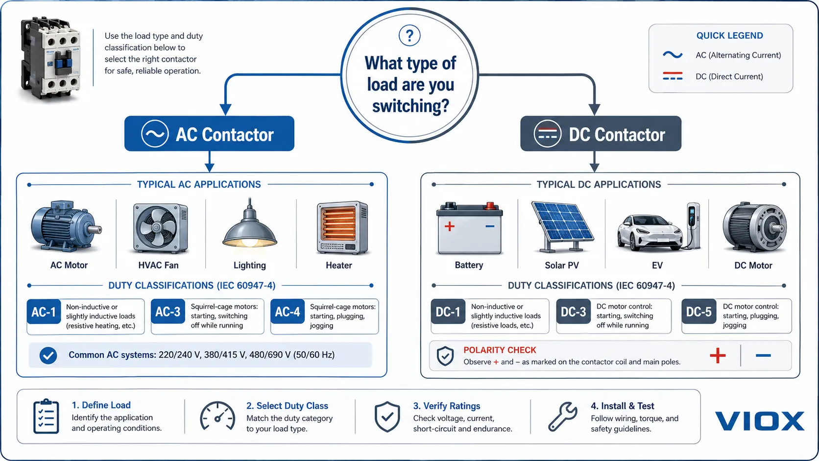
The main difference between an AC contactor and a DC contactor is how each device handles the current it switches. An AC contactor is designed for alternating current, where the current naturally passes through zero many times per second. A DC contactor is designed for direct current, where the arc has no natural zero-crossing and is much harder to extinguish.
This difference affects almost every important part of the contactor: the coil, magnetic core, contact gap, arc chute, contact material, polarity marking, and utilization category. A contactor should never be selected by amperage alone. The load type, voltage type, coil voltage, switching duty, and IEC utilization category must all match the application.
For standard AC motor control, HVAC, lighting, and resistive AC loads, an AC contactor is usually the correct choice. For batteries, solar PV, electric vehicles, DC motors, DC drives, and energy storage systems, a DC-rated contactor is normally required.
AC vs DC Contactor: Quick Comparison
| Feature | AC Contactor | DC Contactor |
|---|---|---|
| Current type | Alternating current (AC) | Direct current (DC) |
| Arc behavior | Arc naturally weakens at each zero crossing | Arc is continuous and harder to extinguish |
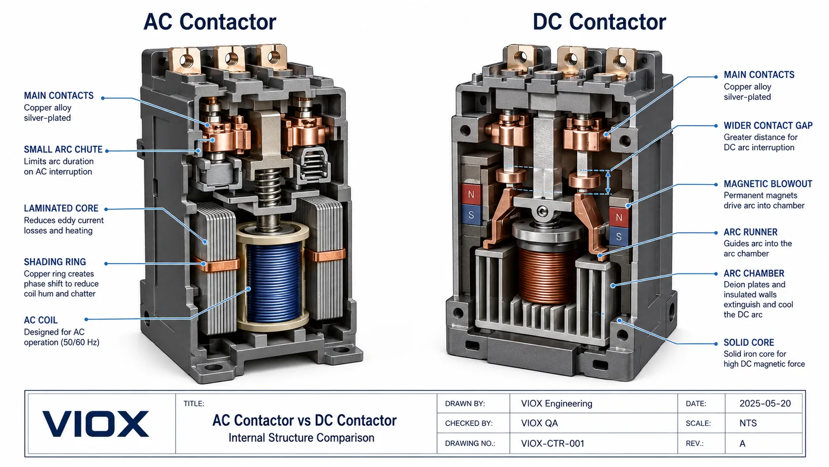
| Magnetic core | Laminated core to reduce eddy-current heating | Solid core is common because flux is steady |
| Shading ring | Usually required to reduce hum and chatter | Not required in a normal DC magnetic system |
| Coil behavior | Coil current is affected by impedance and armature position | Coil current is mainly limited by winding resistance or an economizer circuit |
| Arc suppression | Relies partly on AC zero crossing plus arc chute | Requires stronger arc chute, wider contact gap, magnetic blowout, or sealed arc chamber |
| Polarity sensitivity | Usually not polarity-sensitive on the load side | Some DC contactors are polarity-sensitive due to magnetic arc blowout |
| Typical loads | AC motors, HVAC, pumps, fans, lighting, heaters | Batteries, EVs, solar PV, BESS, forklifts, DC motors, rail and marine DC systems |
| Common IEC categories | AC-1, AC-3, AC-4 | DC-1, DC-3, DC-5 |
| Interchangeability | Do not use for DC unless datasheet permits it | May be usable for some AC loads only if the coil and contact ratings match, but often uneconomical |
What Is an AC Contactor?
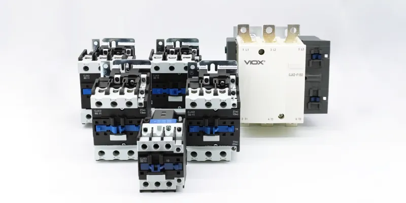
An AC contactor is an electromechanical switching device designed to control AC loads remotely. It uses a coil to create a magnetic field that pulls in an armature, closing the main contacts and allowing current to flow to the load.
AC contactors are widely used in:
- three-phase induction motor control
- HVAC compressors and fans
- pumps and blowers
- lighting circuits
- resistive heating loads
- capacitor banks, when a capacitor-duty contactor is specified
- general industrial control panels
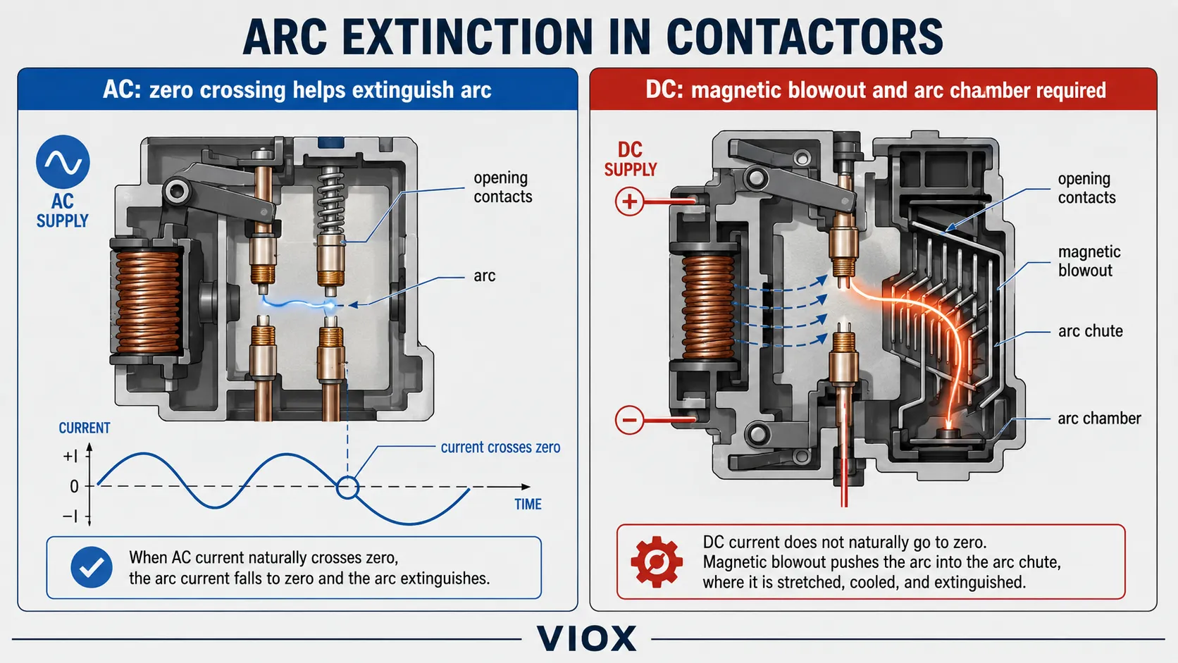
The key design point is that AC current crosses zero every half cycle. In a 50 Hz system, there are 100 zero crossings per second. In a 60 Hz system, there are 120 zero crossings per second. This helps the contactor extinguish the arc when the contacts open.
That does not mean AC arcs are harmless. Contactors still need correct utilization ratings, proper contact materials, and suitable arc chambers. But AC switching is usually less demanding than DC switching at the same voltage and current because the current naturally helps the arc die out.
For AC motor control products, see the VIOX AC contactor product range.
What Is a DC Contactor?
A DC contactor is a contactor designed to switch direct current loads. Since DC current does not pass through zero naturally, a DC arc can continue after the contacts open unless the contactor is designed to force the arc to stretch, cool, split, or move into an arc chamber.
DC contactors are commonly used in:
- battery energy storage systems (BESS)
- electric vehicles and EV charging systems
- solar PV DC circuits
- DC motors and DC drives
- forklifts and automated guided vehicles (AGVs)
- railway and marine DC power systems
- telecom DC power distribution
- emergency DC control and backup systems
DC contactors are becoming more important as solar, battery, EV, and DC distribution systems grow. However, a DC contactor is not just an AC contactor with a different label. The internal arc-control design is different.
AC Coil vs DC Coil
The coil is one of the easiest places to make a selection mistake.
AC Contactor Coil
An AC coil is powered by alternating current. Its current is limited by both winding resistance and inductive reactance. When the armature is open, the magnetic air gap is large and the coil can draw higher inrush current. After the armature closes, the magnetic circuit improves and the holding current drops.
Most AC contactors use a laminated magnetic core and a shading ring. The laminated core reduces eddy-current heating. The shading ring helps maintain magnetic pull during the moments when AC current passes through zero, reducing hum and chatter.
DC Contactor Coil
A DC coil is powered by direct current. Since steady DC does not create the same alternating magnetic flux as AC, the magnetic core is often solid rather than laminated. The coil current is mainly limited by winding resistance or by an electronic economizer circuit in larger contactors.
Many larger DC contactors use a pickup-and-hold strategy. The contactor may need higher power to pull in, then lower power to stay closed. An economizer reduces coil heating and energy consumption after the contactor has closed.
Coil Surge Suppression: Back-EMF and Inductive Kickback
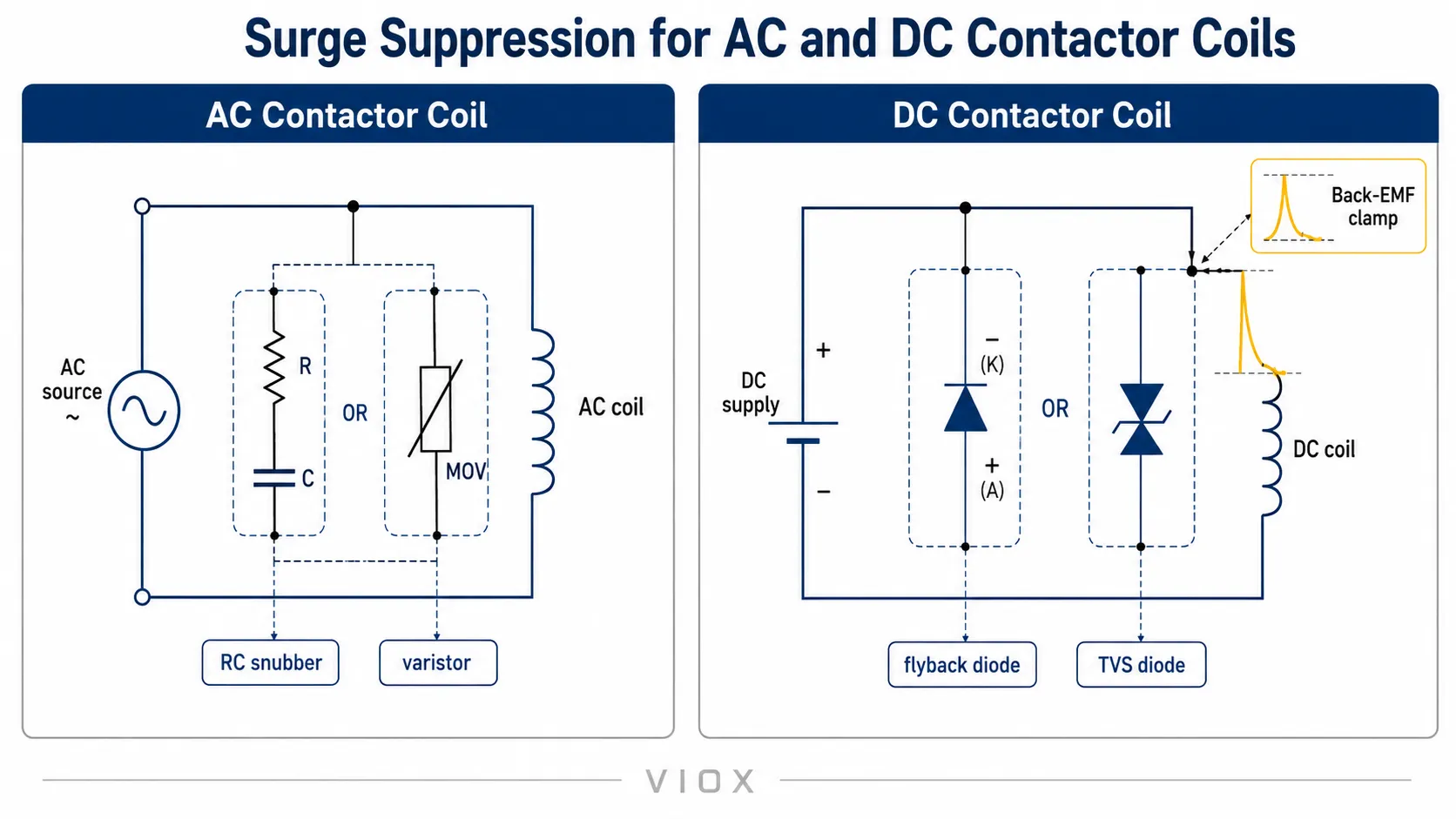
The coil itself is an inductive load. When the control circuit turns the coil off, the collapsing magnetic field can generate a voltage spike known as back electromotive force (Back-EMF) or inductive kickback. If this spike is not controlled, it can damage PLC outputs, relay contacts, timer contacts, sensors, or electronic control boards.
For AC coils, suppression is often handled with an RC snubber or varistor module, depending on the control circuit and manufacturer accessory range. For DC coils, a flyback diode is common in simple circuits, while a transient voltage suppressor (TVS) diode or dedicated surge suppressor may be preferred when faster release time is required.
This detail matters in automation panels. A flyback diode clamps the voltage spike effectively, but it can slow the release of the contactor because the coil current decays more slowly. In emergency stop, safety, or high-speed sequencing circuits, always check the contactor release time and the approved suppression accessory in the datasheet.
What Happens If the Coil Voltage Is Wrong?
Applying the wrong coil supply can cause immediate problems:
- A DC coil connected to AC may chatter, overheat, or fail to close correctly.
- An AC coil connected to DC may overheat because it lacks the intended AC impedance behavior.
- A 24 V coil cannot be assumed to accept both 24 V AC and 24 V DC unless the datasheet explicitly says so.
- A universal AC/DC coil is a special design, not a default feature.
Always check the coil voltage and current type on the contactor label or datasheet.
Laminated Core vs Solid Core
The magnetic core is another major difference.
| Core Feature | AC Contactor | DC Contactor |
|---|---|---|
| Magnetic flux | Alternating | Steady |
| Eddy current risk | Higher | Much lower |
| Typical core construction | Laminated silicon steel | Solid iron or steel is common |
| Shading ring | Common | Not normally needed |
| Common failure symptom | Buzzing, chatter, overheating if coil or shading ring fails | Coil overheating if voltage or economizer is wrong |
In an AC contactor, the magnetic field is constantly changing. A solid core would allow circulating eddy currents and generate heat. Laminated sheets interrupt those circulating current paths.
In a DC contactor, the magnetic field is steady after energization, so eddy-current heating is less of a problem. A solid core can be used efficiently.
This is why the training-style question “AC contactor assemblies are made of laminated ___, while DC assemblies are solid” points to the magnetic core difference.
Why DC Contactors Need Stronger Arc Suppression
When a contactor opens under load, the contacts separate but current may continue through an arc. The difficulty is not only opening the contacts; it is safely extinguishing the arc.
AC Arc Extinction
In an AC circuit, the current naturally crosses zero. At that moment, the arc loses energy. If the contact gap and arc chamber have recovered enough dielectric strength, the arc does not re-strike.
AC contactors still use arc chutes and proper contact geometry, but the zero-crossing gives them a major advantage.
DC Arc Extinction
In a DC circuit, there is no natural zero-crossing. Once the arc forms, it can continue burning if the contactor cannot force it to extinguish. This can lead to contact erosion, contact welding, insulation damage, or failure to interrupt the load safely.
DC contactors may use:
- wider contact gaps
- magnetic blowout structures
- arc runners
- stronger arc chutes
- sealed arc chambers
- gas-filled or vacuum designs in some high-performance contactors
- polarity-specific arc control
For a deeper explanation of electric arcs and arc chambers, see VIOX’s guide on what an arc is in a circuit breaker.
Are DC Contactors Polarity Sensitive?
Some DC contactors are polarity-sensitive, especially those using permanent magnets for arc blowout. The magnetic field is designed to push the arc in a specific direction into the arc chute. If the current direction is reversed, the arc may be pushed away from the intended arc path.
This is why DC contactor terminals may be marked with polarity or line/load direction. Do not ignore those markings. In battery and PV systems, reverse current, charging/discharging direction, and bidirectional operation must be considered during selection.
If the application requires bidirectional current flow, confirm that the contactor is rated for that use. Do not assume every DC contactor is bidirectional.
Contact Materials and Contact Wear
AC and DC switching can stress contact surfaces differently.
AC contactors commonly use silver alloy contacts designed for AC motor and resistive load switching. DC contactors may require contact materials and structures that better resist DC arc erosion and material transfer.
Important contact-related checks include:
- rated operational voltage
- rated operational current
- utilization category
- electrical life curve
- contact gap
- arc chute design
- polarity marking
- load inductance
- expected switching frequency
- short-circuit protection coordination
Contact welding is often caused by excessive inrush, wrong utilization category, short-circuit events, DC misapplication, or insufficient arc suppression for the load.
IEC Utilization Categories: AC-1, AC-3, DC-1, DC-3, DC-5
The same physical contactor frame can have different current ratings depending on the load category. This is one of the most important selection rules.
IEC utilization categories are used to describe the type of load and switching duty. For contactors and motor starters, these categories are associated with the IEC 60947-4-1 framework.
| Category | Typical Load | Practical Meaning |
|---|---|---|
| AC-1 | Non-inductive or slightly inductive AC loads, such as resistive heating | Easier AC switching duty |
| AC-3 | Squirrel-cage motors, starting and switching off during running | Common motor contactor duty |
| AC-4 | Plugging, inching, reversing motor duty | Much harsher motor switching duty |
| DC-1 | Non-inductive or slightly inductive DC loads | Easier DC switching duty |
| DC-3 | Shunt DC motors, starting, plugging, inching, dynamic braking | More demanding DC motor duty |
| DC-5 | Series DC motors, starting, plugging, inching, dynamic braking | Heavy DC motor duty |
This is why a contactor rated for a high current in AC-1 may have a much lower rating in AC-3 or DC categories. The label current alone is not enough.
Can You Use an AC Contactor for DC?
In general, do not use an AC contactor for a DC load unless the manufacturer’s datasheet explicitly permits it for that DC voltage, current, and utilization category.
The risk is not that the coil cannot pull in. The bigger risk is that the main contacts cannot safely interrupt the DC arc. At low DC voltage and low current, some manufacturers may allow special pole-series wiring or derating. But this must come from the datasheet, not guesswork.
High-current battery, solar PV, EV, and DC motor circuits should use contactors specifically rated for DC switching.
Can You Use a DC Contactor for AC?
Sometimes a DC contactor may be physically capable of interrupting an AC load, but it is not automatically the correct choice.
You must check:
- whether the main contacts are rated for the AC voltage and load category
- whether the coil supply matches the control circuit
- whether the contactor is over-sized or uneconomical for the job
- whether the application needs an AC utilization category such as AC-1 or AC-3
In many ordinary AC motor applications, a standard AC contactor is simpler, cheaper, and more appropriate.
Application Guide: When to Use Each Type
| Application | Recommended Contactor Type | Reason |
|---|---|---|
| Three-phase induction motor | AC contactor | Designed for AC motor utilization categories such as AC-3 |
| HVAC compressor or fan | AC contactor | Common definite-purpose or motor contactor application |
| Resistive AC heater | AC contactor | AC-1 duty may apply depending on design |
| Lighting bank | AC contactor | Use suitable lighting duty rating |
| Solar PV DC switching | DC contactor | Requires DC arc interruption capability |
| Battery energy storage | DC contactor | High DC current and possible polarity/bidirectional concerns |
| EV battery disconnect | DC contactor | Safety-critical DC switching application |
| Forklift or AGV DC motor | DC contactor | DC motor duty may require DC-3 or DC-5 consideration |
| DC drive system | DC contactor | Must match voltage, current, inductance, and duty |
Contactor Types: Where AC and DC Fit
The phrase contactor types can mean several things. AC vs DC is only one classification.
Common contactor types include:
- AC contactor
- DC contactor
- modular contactor
- capacitor-duty contactor
- definite-purpose contactor
- reversing contactor
- safety contactor
- vacuum contactor
- contactor relay
For building automation and DIN rail distribution applications, a modular contactor may be more suitable than a standard motor contactor. For motor protection, the contactor is often used together with an overload relay or motor starter, not by itself.
Selection Checklist for AC and DC Contactors
Before choosing a contactor, confirm the following:
| Selection Item | What to Check |
|---|---|
| Load current type | AC or DC |
| Main contact voltage | Rated operational voltage for the load |
| Main contact current | Rated operational current under the correct utilization category |
| Coil voltage | Control voltage and AC/DC coil type |
| Load type | Motor, heater, battery, PV, lighting, capacitor, DC drive |
| Utilization category | AC-1, AC-3, AC-4, DC-1, DC-3, DC-5, or other relevant category |
| Switching frequency | Expected operations per hour or duty cycle, checked against datasheet |
| Arc suppression | AC zero-crossing design or DC magnetic/arc-chute design |
| Polarity | Required for many DC contactors |
| Short-circuit protection | Fuse, MCB, MCCB, or upstream protection coordination |
| Environment | Temperature, vibration, dust, humidity, enclosure type |
| Accessories | Auxiliary contacts, interlocks, suppressors, economizers |
For a broader contactor overview, see VIOX’s guide on what a contactor is.
Engineer’s Field Note: The Failure Is Usually Not Subtle
In field troubleshooting, a misapplied AC contactor on a DC circuit usually does not fail like a small signal relay with a slightly blackened contact. The common pattern is much more obvious: the contacts weld closed, the arc chute is burned, the plastic body is discolored, or the upstream protection trips after the contactor can no longer interrupt the load.
One useful rule of thumb is this: if the load is a battery string, DC motor, PV string, charger, or energy storage circuit, do not start from the AC motor contactor catalog and “derate by guesswork.” Start from the DC voltage, current direction, load inductance, utilization category, and manufacturer DC breaking data. That is the path that avoids most expensive contactor failures.
Common Mistakes
Mistake 1: Selecting by Amps Only
A 100 A rating does not mean the contactor can switch 100 A in every application. The usable rating depends on voltage, AC/DC type, load category, switching duty, and manufacturer data.
Mistake 2: Ignoring Coil Type
A 24 V AC coil and a 24 V DC coil are not the same unless the product has a universal AC/DC coil. Wrong coil supply can cause chattering, overheating, or failure to close.
Mistake 3: Forgetting Coil Surge Suppression
When a coil is de-energized, back-EMF can damage PLC outputs, timer contacts, or relay contacts. Use the suppression method recommended by the manufacturer, and check whether the suppressor changes release time.
Mistake 4: Using an AC Contactor on a DC Battery Circuit
Battery systems can deliver high fault current and sustain DC arcs. Use a contactor rated for the DC voltage, current, polarity, and duty.
Mistake 5: Ignoring DC Polarity
If a DC contactor uses magnetic arc blowout, polarity may determine whether the arc moves into the arc chute correctly. Always follow terminal markings and datasheet diagrams.
Mistake 6: Forgetting Load Inductance
DC motors, coils, solenoids, and long cable runs can increase switching stress. Inductive DC loads are much harder to interrupt than simple resistive loads.
FAQ
What is a DC contactor used for?
A DC contactor is used for switching DC loads such as batteries, solar PV circuits, EV systems, DC motors, forklifts, energy storage systems, and DC power distribution.
Can I use an AC contactor for DC?
Only if the manufacturer datasheet explicitly permits the contactor for that DC voltage, current, and load category. Otherwise, using an AC contactor for DC can cause sustained arcing, contact welding, or failure to interrupt the circuit.
Do contactor coils need surge suppression?
Often, yes. AC coils commonly use RC snubbers or varistors, while DC coils often use flyback diodes, TVS diodes, or dedicated surge suppressors. The correct accessory depends on the control circuit and the required release time.
Does a flyback diode slow down a DC contactor?
It can. A flyback diode clamps the inductive voltage spike effectively, but it may slow coil current decay and increase contactor release time. For faster release, a TVS diode or manufacturer-approved suppressor may be a better option.
Why do AC contactors hum?
AC contactors can hum because the magnetic field changes with the AC waveform. A shading ring helps reduce chatter, but loose laminations, low voltage, dirt, or a damaged shading ring can increase noise.
Are DC contactors polarity sensitive?
Some DC contactors are polarity-sensitive, especially when they use permanent magnets for arc blowout. Always check the terminal markings and datasheet.
What is AC-3 in contactor ratings?
AC-3 is an IEC utilization category commonly used for squirrel-cage motor starting and switching off during running. It is one of the most common AC motor contactor categories.
What is DC-1 in contactor ratings?
DC-1 is a utilization category for non-inductive or slightly inductive DC loads. It is easier duty than DC motor categories such as DC-3 or DC-5.
Is a relay the same as a contactor?
No. A relay is usually used for lower-power control or signal circuits, while a contactor is designed for switching higher-power loads. For a deeper comparison, see VIOX’s contactor vs relay guide.
Conclusion
AC and DC contactors may look similar from the outside, but they are built for different electrical physics. AC contactors rely partly on natural zero-crossing and use laminated cores, shading rings, and AC utilization ratings. DC contactors must deal with continuous arcs, polarity concerns, wider contact gaps, stronger arc suppression, and DC utilization categories.
For safe selection, start with the load type and current type, then verify the coil voltage, contact voltage, utilization category, polarity, switching frequency, and short-circuit protection. If the application involves batteries, solar PV, EV systems, DC motors, or energy storage, use a contactor specifically rated for DC switching rather than assuming an AC contactor can be adapted.
