
Installing a circuit breaker pan assembly requires precise attention to safety protocols, electrical codes, and proper connection techniques. This comprehensive guide covers everything you need to know about safely and correctly installing integrated busbar pan assemblies that comply with IEC/EN 60947-7-1 standards.
What is a Circuit Breaker Pan Assembly?
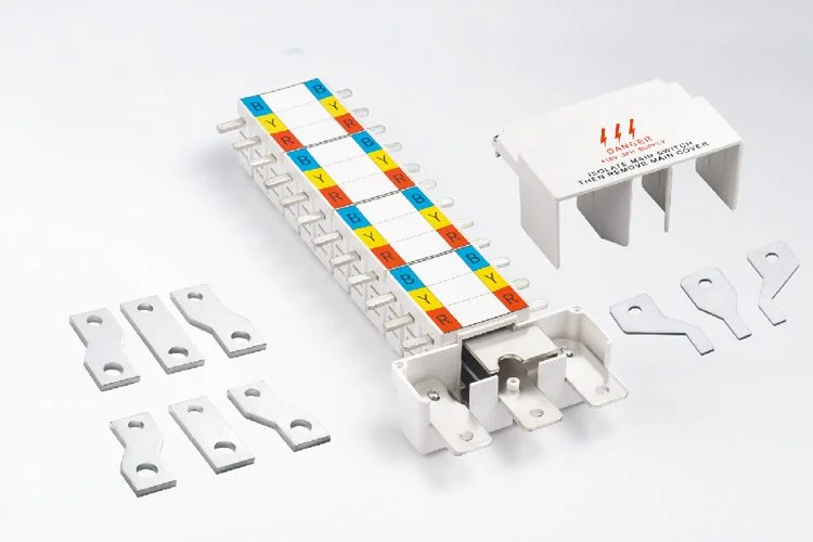
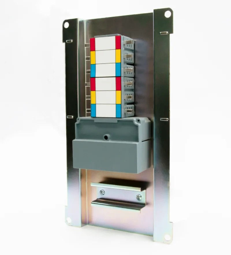
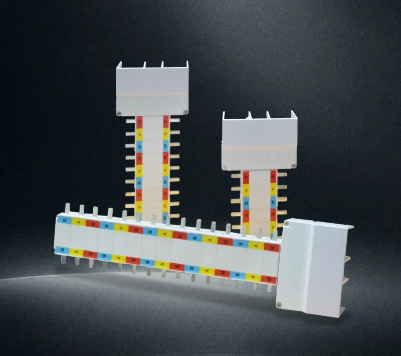
A circuit breaker pan assembly (also called an integrated busbar pan assembly) is a pre-fabricated electrical distribution system that combines the main busbar, circuit breaker mounting bases, and connection terminals in a single unit. These assemblies streamline electrical panel installation while ensuring reliable connections and reducing installation time by approximately 30% compared to traditional wiring methods.
Safety Warning: Professional Installation Required
⚠️ CRITICAL SAFETY NOTICE: Circuit breaker pan assembly installation involves high-voltage electrical work that can cause serious injury or death. This work should only be performed by licensed electricians familiar with local electrical codes. Always disconnect power at the main breaker and verify zero energy state before beginning any electrical work.
Pre-Installation Requirements and Planning
Code Compliance and Standards
- Must comply with IEC/EN 60947-7-1 standards
- Follow local electrical codes (NEC, CEC, or applicable regional standards)
- Obtain proper electrical permits before installation
- Schedule required inspections with local authorities
Required Tools and Materials
- Safety Equipment: Insulated gloves, safety glasses, voltage tester, arc flash protection
- Installation Tools: Torque wrench, wire strippers, screwdrivers, level, measuring tape
- Testing Equipment: Multimeter, insulation resistance tester, phase rotation meter
- Hardware: Appropriate screws, anchors, grounding equipment, wire nuts
Pan Assembly Selection Guide
| Current Rating | Application | Maximum MCB Size | Wire Capacity |
|---|---|---|---|
| 100A-125A | Residential/Small Commercial | 1P-4P MCBs up to 63A | 50mm² main, 16mm² branch |
| 160A | Commercial Applications | 1P-4P MCBs up to 63A | 50mm² main, 16mm² branch |
| 200A | Industrial/Large Commercial | 1P-4P MCBs up to 63A | 50mm² main, 16mm² branch |
| 225A | Heavy Industrial | 1P-4P MCBs up to 63A | 50mm² main, 70mm² ground |
Step-by-Step Installation Process
Step 1: Power Isolation and Verification
- Turn off main power at the service entrance
- Lock out and tag out the main disconnect
- Test with voltage meter to confirm zero energy state
- Verify testing equipment is functioning properly
- Post warning signs to prevent accidental energization
Step 2: Panel Preparation and Mounting
- Location Assessment: Ensure adequate clearance (minimum 3 feet working space in front)
- Wall Mounting: Use appropriate anchors rated for panel weight plus 25% safety factor
- Leveling: Install panel perfectly level using precision level
- Grounding: Install equipment grounding conductor per code requirements
- Enclosure: Verify enclosure is properly sealed and meets IP rating requirements
Step 3: Busbar Installation and Connection
- Busbar Alignment: Verify copper busbar is properly seated in mounting bases
- Torque Specifications: Tighten busbar connections to manufacturer specifications (typically 25-35 Nm)
- Phase Identification: Apply appropriate phase labels (L1/L2/L3 or regional equivalent)
- Insulation: Ensure proper insulation barriers between phases
- Connection Verification: Visually inspect all connections for proper contact
Step 4: MCB Mounting and Configuration
- MCB Selection: Verify MCB ratings match circuit requirements
- Mounting Procedure:
- Align MCB with busbar connections
- Press firmly until positive engagement click
- Verify mechanical and electrical connection
- Test MCB operation (on/off function)
- Phase Configuration: Install single-pole, two-pole, three-pole, or four-pole MCBs as required
- Spacing Verification: Ensure proper spacing between MCBs for heat dissipation
Step 5: Wire Connections and Terminations
Main Line Connections
- Neutral Wire: Connect to neutral bar using appropriate termination (up to 50mm²)
- Ground Wire: Connect to ground bar using appropriate termination (up to 35mm²)
- Phase Conductors: Connect to main lugs with proper torque specifications
Branch Circuit Connections
- Load Wires: Connect branch circuits to MCB load terminals
- Wire Management: Route wires neatly to prevent interference with MCB operation
- Labeling: Apply circuit identification labels per code requirements
Step 6: Testing and Verification
- Insulation Resistance: Test insulation between phases and to ground (minimum 1MΩ)
- Continuity Testing: Verify all connections have proper continuity
- Phase Rotation: Confirm correct phase sequence for three-phase installations
- Ground Fault: Test GFCI/RCD devices if installed
- Load Testing: Gradually apply loads to verify proper operation
Troubleshooting Common Installation Issues
Connection Problems
- Loose Connections: Retorque to specification, check for proper wire preparation
- Overheating: Verify proper wire size, check for loose connections
- Arcing: Ensure clean connections, proper torque, adequate wire capacity
MCB Installation Issues
- Poor Contact: Verify MCB is fully seated, check busbar alignment
- Mechanical Binding: Check for obstructions, verify proper MCB spacing
- Electrical Faults: Test MCB independently, verify proper voltage ratings
System Performance
- Voltage Drop: Check connection integrity, verify wire sizing
- Ground Faults: Test insulation resistance, check for moisture ingress
- Phase Imbalance: Verify equal loading, check connection quality
Maintenance and Inspection Schedule
Monthly Visual Inspections
- Check for signs of overheating or discoloration
- Verify all connections remain tight
- Inspect for moisture or contamination
- Test MCB operation
Annual Professional Inspection
- Thermographic scanning of connections
- Insulation resistance testing
- Connection torque verification
- Complete electrical safety audit
Frequently Asked Questions
Q: Can I install different MCB brands in the same pan assembly?
A: Only use MCBs specifically certified for your pan assembly model. Mixing brands can create safety hazards and void certifications.
Q: What wire types are compatible with these assemblies?
A: Use copper conductors only, with appropriate insulation ratings. Wire capacity varies by model: typically 50mm² for main connections and 16mm² for branch circuits.
Q: How do I determine the correct pan assembly size?
A: Calculate total load requirements, add 25% safety factor, and select the next larger standard size. Consider future expansion needs.
Q: Are these assemblies suitable for outdoor installation?
A: Only when installed in appropriate weatherproof enclosures. The pan assembly itself requires protection from moisture and environmental elements.
Q: What certifications should I look for?
A: Ensure IEC/EN 60947-7-1 compliance, CE marking, and relevant local certifications (UL, CSA, etc.).
Q: How often should connections be retightened?
A: Initial retightening after 6 months of operation, then annually or per manufacturer recommendations.
Professional Installation Best Practices
Expert Safety Tips
- Always use appropriate PPE including arc flash protection
- Implement lockout/tagout procedures religiously
- Double-check all connections before energizing
- Maintain detailed installation records for future reference
Quality Assurance Checklist
- ✓ All connections torqued to specification
- ✓ Proper phase identification and labeling
- ✓ Insulation resistance tests passed
- ✓ Ground fault protection functional
- ✓ Load distribution balanced across phases
- ✓ Documentation complete and filed
When to Call a Professional
Contact a licensed electrician immediately if you encounter:
- Any signs of electrical arcing or burning
- Uncertainty about code compliance requirements
- Complex three-phase installations
- Integration with existing electrical systems
- Any safety concerns during installation
Remember: Proper installation of circuit breaker pan assemblies ensures safe, reliable electrical distribution for years to come. When in doubt, always consult with qualified electrical professionals and local code authorities to ensure compliance and safety.
