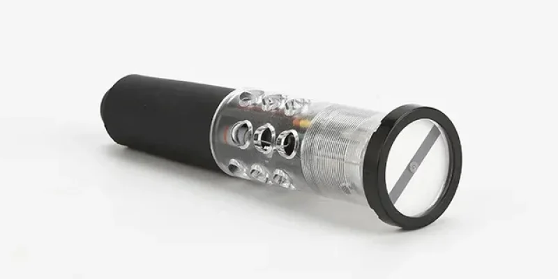
Switch position indicators are essential components in electrical installations, providing visual feedback on the status of valves, actuators, and switches. Installing these devices typically involves mounting the indicator, aligning it with the associated equipment, and making proper electrical connections to ensure accurate position signaling.

VIOX Switch Position Indicators
Preparation and Safety
Before beginning the installation process, prioritize safety by ensuring all power to the circuit is turned off to prevent electrical shock or equipment damage. Gather necessary tools such as screwdrivers, wire strippers, and potentially a drill for mounting holes. Carefully review the installation manual specific to your switch position indicator model, as requirements may vary depending on the type and manufacturer. This preparation step is crucial for a smooth and safe installation process, allowing you to familiarize yourself with any unique specifications or requirements for your particular indicator.
Mounting the Indicator
Begin by selecting an appropriate location for the indicator that ensures visibility and accessibility. Align the indicator’s shaft with the valve or actuator shaft for accurate position readings. Depending on the model, you may need to use a mounting bracket, which should be securely attached to both the indicator and the valve/actuator. Fasten the indicator to the mounting surface using screws and washers, ensuring it’s firmly in place to prevent movement during operation. For specific models like the Elektrogas valves or actuators, an adapting rod may be pre-mounted to simplify installation. When installing on soft-seated butterfly valves, mount the indicator assembly onto the valve stem and secure it with screws and washers.
Electrical Connections
When making electrical connections for switch position indicators, follow these key steps:
- Identify the correct terminals on the indicator for power input and signal output. Most models have screw terminals that can accommodate wire cross-sections up to 1.5 mm².
- Connect the power supply, ensuring it matches the indicator’s voltage requirements. Many indicators operate on a wide range, such as 24-230V AC or DC.
- Wire the output signals to the control system or display panel as specified in the device manual.
- Use appropriate cable glands or conduit entrances to maintain the indicator’s IP54 rating and protect against environmental factors.
- Always verify connections and test the indicator’s functionality before finalizing the installation. For safety, ensure the power is off during wiring and adhere to local electrical codes and manufacturer guidelines.
Testing and Maintenance
After completing the installation, restore power to the circuit and test the switch position indicator by operating the associated valve or actuator. The indicator should accurately reflect the equipment’s position, such as open/closed for valves or extended/retracted for actuators. If discrepancies are observed, recheck wiring connections and alignment. Regular maintenance is crucial for ensuring continued accurate operation. Periodically inspect the indicator for proper functionality, checking that it remains securely mounted and correctly aligned with the equipment it monitors. This ongoing maintenance helps to identify and address any potential issues before they impact the reliability of the position indication system.


