
Samlingsskenor spelar en avgörande roll i elektriska kraftdistributionssystem genom att ansluta effektbrytare och ge effektiv kraftdistribution samtidigt som de ger tillförlitligt skydd mot överbelastning i motorkretsar. Dessa viktiga komponenter har en rad olika strömstyrkor, från 63A till 160A, och innehåller olika skyddsmekanismer för att skydda elektriska system och utrustning.

Specifikationer för samlingsskenor för effektbrytare
Samlingsskenor för effektbrytare är konstruerade för att hantera olika elektriska parametrar och konfigurationer:
- Strömkapaciteten sträcker sig från 63 A för 10 mm² samlingsskenor till 160 A för 35 mm² versioner, lämpliga för tunga belastningar och höga omgivningstemperaturer.
- Nominell driftspänning 400 V AC med 4 kV impulsspänning och 6,2 kV testpulsspänning.
- Finns i enfas-, tvåfas-, trefas- och fyrfasutförande.
- Nominell villkorlig kortslutningsström på 25 kA.
- Flexibla installationsalternativ med fasta längder eller system för kapning till längd och olika stegavstånd (45 mm, 54 mm och 63 mm).
Dessa specifikationer säkerställer effektiv kraftdistribution och skydd i elcentraler och motorkretsar.
Samlingsskenans materialsammansättning
Samlingsskenor för kretsbrytare tillverkas vanligtvis av högkvalitativa ledande material, där koppar är det vanligaste valet på grund av dess utmärkta elektriska egenskaper. Kopparskenor har överlägsen ledningsförmåga, näst efter silver, och har exceptionell styrka och termiska expansionsegenskaper. De uppvisar också hög korrosionsbeständighet, vilket gör dem idealiska för långvarig användning i elektriska system.
Aluminium är ett annat material som används för samlingsskenor och som erbjuder ett lättare alternativ till koppar. Även om aluminium har ungefär 62% av kopparens ledningsförmåga ger det kostnadsbesparingar vid transport och installation. I vissa skensystem används en kombination av olika material, t.ex. kopparledare med isolering av ABS-plast. Isoleringen, som ofta är tillverkad av värmebeständiga material som Cycoloy 3600, ökar säkerheten genom att vara flamskyddad och självsläckande. Kombinationen av ledande metaller och isolerande plaster säkerställer effektiv kraftdistribution samtidigt som höga säkerhetsstandarder upprätthålls i applikationer med effektbrytare.
Applikationer och tillverkarkompatibilitet
Samlingsskenor används ofta i anslutningar till motorskyddsbrytare, i elcentraler och för strömfördelning i kontrollpaneler och har många användningsområden i elsystem. De är kompatibla med enheter från stora tillverkare som ABB, Allen Bradley, Eaton, Siemens och Schneider Electric. Systemets snabba och tidsbesparande kabeldragning, tillsammans med dess utdragbara design, ger flexibilitet för olika industriella och kommersiella miljöer. Inom anläggningsteknik är samlingsskenor utmärkta för att ansluta kraftkontaktorer, vilket förbättrar systemets totala effektivitet och tillförlitlighet.
Skyddsmekanismer för överbelastning
Termiskt skydd är en viktig egenskap hos samlingsskenesystem, med bimetallremsor som böjs som svar på överdriven värme som genereras av höga strömmar. Denna mekanism övervakar kontinuerligt strömflödet och utlöser en utlösning när förinställda gränser överskrids, vilket förhindrar motorskador. För ökad säkerhet och effektivitet är skyddsanordningarna strategiskt placerade nära motorn, vilket möjliggör ett decentraliserat skydd. Kopplingsdosor innehåller termomagnetiska kretsbrytare och motoriserade brytare, vilket underlättar effektiv systemhantering och samordning mellan skyddskomponenter. Detta integrerade tillvägagångssätt säkerställer ett omfattande överbelastningsskydd samtidigt som onödig stilleståndstid i motorkretsar minimeras.
Integrering av MCB-samlingsskenor
Miniatyrbrytare (MCB) integreras sömlöst med samlingsskenor genom innovativa snap-on-fästsystem och specialkonstruerade samlingsskenor. Denna integration ger flera fördelar:
- Snabb och enkel installation: MCB:er kan snabbt monteras på strömskenor med hjälp av snap-on-teknik, vilket sparar upp till 50% i monteringstid jämfört med traditionella ledningsmetoder.
- Utrymmesbesparande design: Samlingsskenesystemens kompakta konstruktion gör det möjligt att utnyttja panelutrymmet effektivt, och vissa konstruktioner rymmer upp till 57 MCB-poler i en enda enhet.
- Förbättrad säkerhet: Integrerade beröringsskydd, t.ex. fingersäkra plintskydd, garanterar operatörens säkerhet vid installation och underhåll.
- Flexibilitet: Samlingsskenesystem kan enkelt förlängas eller modifieras, vilket möjliggör enkla konfigurationsändringar och byte av enheter utan verktyg.
Integrationsprocessen innebär vanligtvis att MCB:n riktas in mot samlingsskenans stiftanslutningar och snäpps fast på plats. Den här metoden säkerställer korrekt fasinriktning och konsekventa anslutningar i hela enheten, vilket minskar sannolikheten för kabeldragningsfel och förbättrar systemets övergripande tillförlitlighet.
Anslutningsmetoder för samlingsskenor
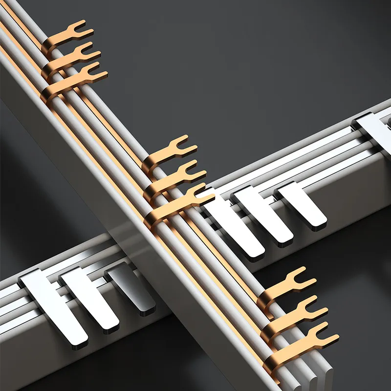
Samlingsskenans anslutningar för effektbrytare är utformade för effektiv och säker strömfördelning i elsystem. Dessa anslutningar har vanligtvis en stift- eller kamliknande struktur som gör det möjligt att snabbt och enkelt installera effektbrytare på samlingsskenan. Samlingsskenesystemet har specialdesignade fingrar eller stift som sträcker sig utåt från den ledande skenan och är placerade så att de matchar centrumavståndet för effektbrytare.Viktiga egenskaper hos anslutningar till samlingsskenor för effektbrytare är bl.a:
- Quick-release-teknik för enkel installation och demontering av effektbrytare
- No-miss busbar-teknik för att säkerställa korrekt inriktning och anslutning
- Kompatibilitet med olika typer av effektbrytare, inklusive MCB, RCBO och RCCB
- Finns i flera polkonfigurationer (1P, 2P, 3P, 4P) för att tillgodose olika kretsbehov
- Strömklassningar från 63A till 400A, beroende på det specifika samlingsskenesystemet
- Isolering och skyddskåpor för att garantera säkerheten under installation och drift
Dessa anslutningssystem minskar installationstiden avsevärt jämfört med traditionella kabeldragningsmetoder, samtidigt som de förbättrar systemets tillförlitlighet och säkerhet.
Säkerhetsrutiner för samlingsskenor
Samlingsskenorna har flera säkerhetsfunktioner för att skydda arbetarna vid installation och underhåll:
- Beröringsskydd förhindrar oavsiktlig kontakt med spänningsförande ledare. Dessa skydd kan förlängas eller justeras för att passa olika samlingsskenekonfigurationer.
- Korrekt märkning av spänning, fas och polaritet förhindrar förvirring och misstag vid installation eller service.
- Isolationsmotståndstest och visuella inspektioner utförs för att identifiera potentiella faror som sprickor i isoleringen eller felaktiga anslutningar innan arbetet påbörjas.
- Personlig skyddsutrustning, inklusive långärmad jacka, handskar och skyddsglasögon, krävs vid hantering av strömskenor.
- Låsning/taggning säkerställer att strömmen är helt bortkopplad före underhåll, och att huvudströmmen återställs först när arbetet är klart och åtkomstdörrarna är stängda.
- Regelbundet underhåll, inklusive åtdragning av anslutningar, rengöring av korrosion och applicering av korrosionsskyddsmedel, förbättrar ytterligare den långsiktiga säkerheten och tillförlitligheten hos samlingsskenesystem.
Installationsprocess för MCB-samlingsskenor
Installation av en MCB-samlingsskena kräver noggrann uppmärksamhet på detaljer och efterlevnad av säkerhetsprotokoll. Här är de viktigaste stegen:
- Samla ihop nödvändiga verktyg, t.ex. borrmaskin, måttband och säkerhetsutrustning som handskar och skyddsglasögon.
- Mät och kapa samlingsskenan till önskad längd, så att den passar avståndet mellan anslutningspunkterna.
- Rengör monteringsytan noggrant för att avlägsna smuts och fett.
- Rikta in samlingsskenan mot monteringsytan och fäst den med lämpliga bultar eller skruvar.
- Lossa alla skruvar på luftväxlarna innan du sätter i strömskenans tänder.
- För försiktigt in samlingsskenan i MCB:n och se till att den är korrekt inriktad mot anslutningsterminalerna.
- Dra åt alla skruvar enligt tillverkarens rekommenderade åtdragningsmoment.
- Dubbelkontrollera att alla foglock är ordentligt fastsatta och att avtappningslådorna är korrekt installerade.
Se alltid tillverkarens anvisningar och lokala elföreskrifter för specifika krav. Om du är osäker, kontakta en behörig elektriker för att säkerställa en säker och korrekt installation.

Procedur för inkoppling av MCB-samlingsskenor
Följ dessa steg för att koppla en MCB-samlingsskena på rätt sätt:
- Se till att strömmen är avstängd och använd lämplig säkerhetsutrustning.
- Identifiera linje- (ingång) och lastterminalerna (utgång) på MCB:n. Linjeterminalen är vanligtvis märkt "LINE" eller har en pil som pekar mot den.
- Anslut den ingående strömförsörjningen till MCB:ns linjeterminal.
- Anslut samlingsskenan till MCB:ns lastterminal. De flesta moderna MCB:er har ett "no miss"-anslutningssystem för samlingsskenor för enkel installation.
- För flera MCB:er, rikta in dem på DIN-skenan och skjut samlingsskenan på plats och se till att den ansluts till varje MCB:s lastplint.
- Säkra samlingsskenan genom att dra åt skruvarna till tillverkarens rekommenderade vridmoment (vanligtvis cirka 3 Newtonmeter).
- Anslut de utgående kretsledningarna till lämpliga plintar på samlingsskenan.
- Dubbelkolla alla anslutningar innan strömmen återställs.
Kom ihåg att felaktig kabeldragning kan leda till MCB-fel eller till att MCB inte löser ut när det behövs. Om du är osäker, kontakta en behörig elektriker för att säkerställa en säker och korrekt installation.
Utmaningar vid installation av MCB-samlingsskenor
Vid installation av MCB-samlingsskenor stöter elektriker ofta på flera vanliga problem:
- Felaktig inriktning av samlingsskenans stift: De krökta eller förskjutna stiften i änden av flexibla samlingsskenor kan göra att MCB:erna skjuts ur linje med RCD:er eller DIN-skenan när de dras åt. Denna felaktiga inriktning kan leda till felaktiga anslutningar och potentiella säkerhetsrisker.
- Inkompatibla MCB-modeller: Olika tillverkare kan ha olika MCB-design, vilket leder till problem med anpassning till befintliga samlingsskenesystem. Denna inkompatibilitet kan göra det nödvändigt att byta ut flera komponenter eller hitta alternativa kabeldragningslösningar.
- Felaktig placering av samlingsskenor: Felaktigt placerade samlingsskenor i MCB:er kan generera värme, vilket påskyndar termiska utlösningsegenskaper och orsakar frekventa brytarutlösningar. Det här problemet kan vara svårt att upptäcka visuellt och kräver noggrann installation och testning.
- Användning av kabel istället för samlingsskena: Vissa installatörer försöker använda kabelbitar som ersättning för korrekta samlingsskenor, vilket kan leda till flimrande lampor och potentiell ljusbåge på grund av felaktiga anslutningar. Denna metod är osäker och överensstämmer inte med elektriska standarder.
För att minska dessa problem är det viktigt att använda kompatibla komponenter, säkerställa korrekt inriktning under installationen och undvika provisoriska lösningar som äventyrar säkerheten och tillförlitligheten.
Förebyggande av strömgenomgång i skenor
Ljusbågar i effektbrytarskenor kan utgöra en betydande säkerhetsrisk och skada elektrisk utrustning. Detta fenomen uppstår när elektricitet hoppar över ett mellanrum mellan ledare, vilket skapar en farlig elektrisk urladdning. Vanliga orsaker till ljusbågar i strömskenor är bl.a:
- Lösa anslutningar eller skadade kontakter mellan effektbrytaren och samlingsskenan
- Överbelastade kretsar som drar mer ström än vad systemet kan hantera
- Försämring av isoleringen på grund av ålder, fukt eller fysiska skador
- Felaktiga brytartyper eller felriktade anslutningar orsakar dålig kontakt
För att minska risken för ljusbågar använder elsystem ofta lösningar för skydd mot ljusbågsfel. Dessa kan omfatta dedikerade skyddsreläer för ljusbågar eller optiska detekteringssystem som avsevärt minskar tiden för ljusbågar. Regelbundet underhåll, korrekta installationstekniker och användning av kompatibla komponenter är avgörande för att förhindra ljusbågsfel och säkerställa lång livslängd och säkerhet för samlingsskenesystem.
Tekniker för värmeavledning i samlingsskenor
Effektiv värmeavledning är avgörande för att bibehålla prestanda och livslängd hos samlingsskenesystem. Flera tekniker används för att hantera termiska belastningar:
- Naturlig konvektion: För samlingsskenor med lägre effektavledning (10-100 W) kan naturlig luftkylning vara tillräcklig. Vertikal placering av samlingsskenor kan öka värmeöverföringskoefficienten med 20% jämfört med horisontell placering, vilket förbättrar kylningseffektiviteten.
- Kylning med forcerad luft: Fläktar kan öka värmeavledningen med 5-10 gånger jämfört med naturlig konvektion, vilket möjliggör 2-3 gånger högre strömmar. Den här metoden är effektiv för värmeflöden på cirka 50 W/dm².
- Vattenkylning: För högeffektsapplikationer som IGBT/SiC-moduler kan forcerad vattenkylning hantera värmeflöden på upp till 5 kW/dm².
- Val av material: Samlingsskenor innehåller termiskt ledande material för att förbättra värmeavledningen. Samlingsskenor av koppar har t.ex. utmärkt värmeledningsförmåga.
- Ytbehandlingar: Genom att applicera beläggningar som kolnanorör (CNT) eller bornitrid (BN) kan värmeavledningsegenskaperna förbättras.
Korrekt värmehantering säkerställer optimal prestanda för samlingsskenor, förhindrar överhettning och förlänger livslängden för elektriska system. Valet av kylmetod beror på den specifika applikationen, effektkraven och den tillåtna temperaturökningen.
Relaterad artikel
Samlingsskena av stifttyp VS Samlingsskena av gaffeltyp
Förståelse för samlingsskenor: Ryggraden i kommersiell eldistribution
