
Professionell tillverkare av DC- och AC-SPD | VIOX Electric
VIOX Electric är en ledande SPD-tillverkare specialiserat på högkvalitativa DC-strömförsörjningshastighet och AC-hastighetsreglering Överspänningsskydd. Med över 15 års erfarenhet av tillverkningsexpertis erbjuder vi heltäckande överspänningsskyddslösningar för solcellssystem, bostäder, kommersiella och industriella tillämpningar.
Vår ISO 9001:2015-certifierade anläggning tillverkar överspänningsskydd av typ 1, typ 2 och typ 1+2 som uppfyller internationella standarder, inklusive IEC 61643-11, IEC 61643-31, CE och CSA-certifieringar. Som en betrodd SPD-tillverkare, vi betjänar fler än 500 företag världen över med pålitlig överspänningsskyddsteknik.
Certifierad av


DC SPD-produktsortiment - Solcells- och industriella applikationer
Typ 2 DC SPD för solcellssystem

VSPDN40-DC 500V 2P T2

VSPDN40-DC 600V 2P T2

VSPDN40-DC 800V 2P T2

VSPDN40-DC 1200V 3P T2

VSPDN40-DC 1500V 3P T2
Typ 1+2 DC SPD för förbättrat skydd

VSPDH6.25-DC T1+T2 800V

VSPDH6.25-DC T1+T2 1000V
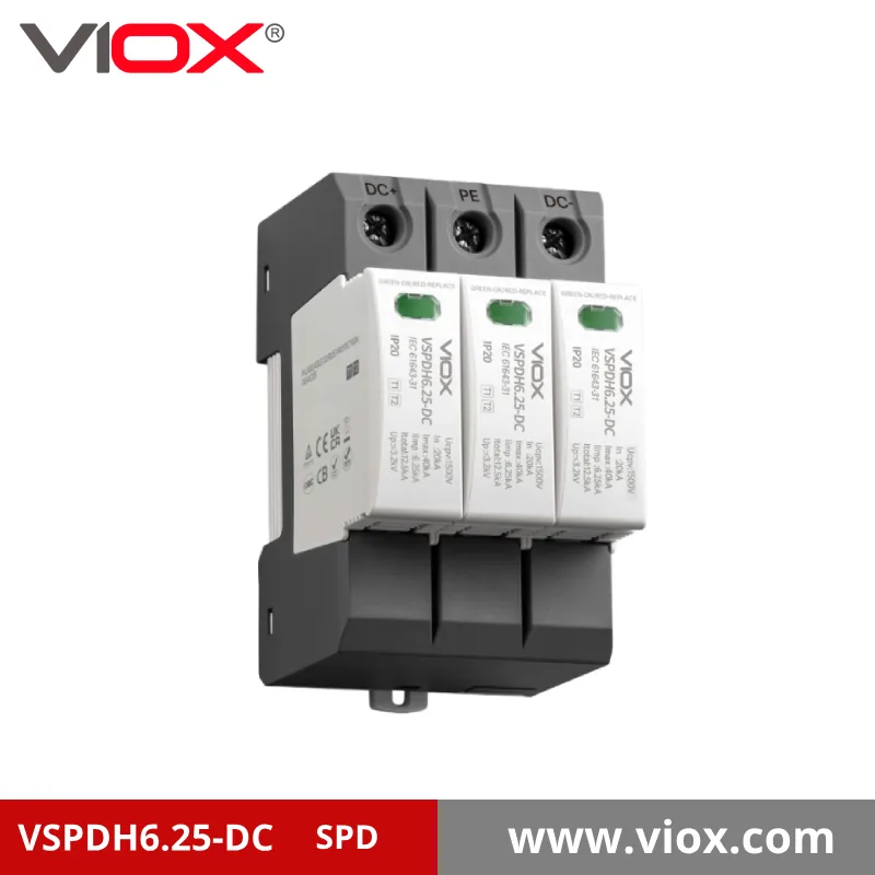
VSPDH6.25-DC T1+T2 1500V

VSPDN40-DC 1200V 3P T2
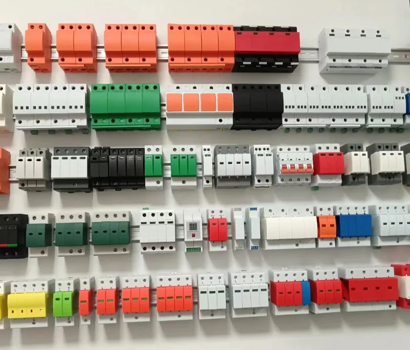
AC SPD-lösningar - Skydd för bostäder och företag
Typ 1 AC SPD för åskskydd

VSPDN40-AC 1P 275V

VSPDN40-AC 2P 275V
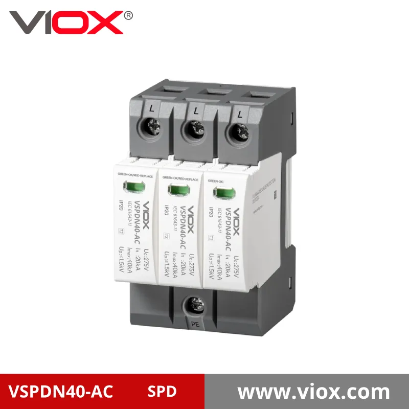
VSPDN40-AC 3P 275V

VSPDN40-AC 4P 275V
Typ 2 AC SPD för överspänningsskydd

VSPDH12.5-AC 275V 1P T1+T2

VSPDH12.5-AC 255V 2P T1+T2

VSPDH12.5-AC 275V 3P T1+T2

VSPDH12.5-AC 275V 4P T1+T2
Överlägsen DC SPD-teknik
Våra överspänningsskydd är konstruerade för att ge maximal säkerhet och tillförlitlighet för solcellssystem
En kort självnominering: Varför välja VIOX Electric?
VIOX Electric är en professionell tillverkare av överspänningsskydd med ISO 9001:2015-certifierade anläggningar där varje överspänningsskydd genomgår rigorös kvalitetsvalidering. Vårt engagemang för excellens har gjort oss till en betrodd partner för elinstallatörer, solcellsinstallatörer och OEM-tillverkare över hela världen.

- Branschledande testerVarje VIOX SPD genomgår rigorösa 100%-tester enligt internationella säkerhetsstandarder.
- Material av högsta kvalitet: Förstklassiga komponenter ger längre livslängd och tillförlitlig prestanda
- Teknisk innovationVårt forsknings- och utvecklingsteam förbättrar kontinuerligt SPD-tekniken för förbättrat skydd
- Global certifieringIEC-, CE-, UL-, CCC-, CB-, TUV- och SAA-certifieringar för hela vårt SPD-sortiment
- Omfattande stöd: Från vägledning vid val till utbildning i installation och service efter försäljning
VIOX SPD-kopplingsschema i PV-system
Korrekt installation av SPD i solcellssystem kräver strategisk placering och korrekt kabeldragning för att säkerställa maximalt skydd. Våra kopplingsscheman visar bästa praxis för integration av DC SPD i solcellsinstallationer.
PV-panel → DC-kombinationsbox → DC-spolargivare → Växelriktare → AC-spolargivare → Elpanel

VIOX SPD Teknisk prestanda


VIOX SPD Teknisk prestanda
| Parameter | Symbol | VSPDN40-DC500 | VSPDN40-DC600 | VSPDN40-DC800 | VSPDN40-DC1000 | VSPDN40-DC1200 | VSPDN40-DC1500 |
|---|---|---|---|---|---|---|---|
| Maximal kontinuerlig driftspänning för likström | Ucpv | 500V likström | 600Vdc | 800Vdc | 1000Vdc | 1200Vdc | 1500Vdc |
| Nominell urladdningsström [8/20 μs] | I | 20kA | 20kA | 20kA | 20kA | 20kA | 20kA |
| Maximal urladdningsström [8/20 μs] | Imax | 40kA | 40kA | 40kA | 40kA | 40kA | 40kA |
| Skyddsnivå för spänning | Upp | ≤2,2 kV | ≤2,8 kV | ≤3,2 kV | ≤3,8 kV | ≤4,5 kV | ≤5,2 kV |
| Kortslutningsströmklassning | Iscpv | 10 kA | 10 kA | 10 kA | 10 kA | 10 kA | 10 kA |
| Svarstid | tA | ≤25ns | ≤25ns | ≤25ns | ≤25ns | ≤25ns | ≤25ns |
| Termisk frånkopplingsenhet | – | Införande | Införande | Införande | Införande | Införande | Införande |
| Max. Reservsäkring | – | 63A gPV-säkring | 63A gPV-säkring | 63A gPV-säkring | 63A gPV-säkring | 63A gPV-säkring | 63A gPV-säkring |
| Skyddsläge | – | +/- → PE | +/- → PE | +/- → PE | +/- → PE | +/- → PE | +/- → PE |
| Konfiguration | – | 2+0 | 2+0 | 2+0 | 3+0 | 3+0 | 3+0 |
| Metod för kabeldragning | – | Skruvterminal 2,5–25 mm² | Skruvterminal 2,5–25 mm² | Skruvterminal 2,5–25 mm² | Skruvterminal 2,5–25 mm² | Skruvterminal 2,5–25 mm² | Skruvterminal 2,5–25 mm² |
| Normal/Fel-visning | – | Grön/Röd | Grön/Röd | Grön/Röd | Grön/Röd | Grön/Röd | Grön/Röd |
| Fjärrsignal | – | Frivillig | Frivillig | Frivillig | Frivillig | Frivillig | Frivillig |
| Maximal fjärrsignalbelastning | – | 250V/0,5A[AC], 30V/3A[DC] | 250V/0,5A[AC], 30V/3A[DC] | 250V/0,5A[AC], 30V/3A[DC] | 250V/0,5A[AC], 30V/3A[DC] | 250V/0,5A[AC], 30V/3A[DC] | 250V/0,5A[AC], 30V/3A[DC] |
| Maximal tvärsnittsarea | – | 1,5 mm² | 1,5 mm² | 1,5 mm² | 1,5 mm² | 1,5 mm² | 1,5 mm² |
| Installation | – | 35 mm DIN-skena | 35 mm DIN-skena | 35 mm DIN-skena | 35 mm DIN-skena | 35 mm DIN-skena | 35 mm DIN-skena |
| Driftstemperaturområde | Tis | -40°C till +85°C | -40°C till +85°C | -40°C till +85°C | -40°C till +85°C | -40°C till +85°C | -40°C till +85°C |
| Skyddsnivå | – | IP20 | IP20 | IP20 | IP20 | IP20 | IP20 |
| Material för kapsling | – | Termoplast (UL94-V0) | Termoplast (UL94-V0) | Termoplast (UL94-V0) | Termoplast (UL94-V0) | Termoplast (UL94-V0) | Termoplast (UL94-V0) |
| Produktstorlek (L×B×H) | – | 90 mm × 49 mm × 67 mm | 90 mm × 49 mm × 67 mm | 90 mm × 49 mm × 67 mm | 90 mm × 49 mm × 67 mm | 90 mm × 49 mm × 67 mm | 90 mm × 49 mm × 67 mm |
| Överensstämmelse med standarder | – | IEC 61643-31, EN 61643-31, GB/T 18802.31 | IEC 61643-31, EN 61643-31, GB/T 18802.31 | IEC 61643-31, EN 61643-31, GB/T 18802.31 | IEC 61643-31, EN 61643-31, GB/T 18802.31 | IEC 61643-31, EN 61643-31, GB/T 18802.31 | IEC 61643-31, EN 61643-31, GB/T 18802.31 |
Anteckningar:
- Alla modeller är DC-överspänningsskydd av typ 2
- Alla modeller använder varistorspänningsbegränsande teknik med låg restspänning
- Alla modeller har en inkopplingsbar design och interna termiska frånkopplingsenheter
- Modellerna VSPDC500, VSPDC600, VSPDC800 använder 2+0-konfiguration
- Modellerna VSPDC1000, VSPDC1200, VSPDC1500 använder 3+0-konfiguration
- Alla modeller är RoHS- och REACH-kompatibla
| Parameter | Symbol | VSPDN40-275 | VSPDN40-320 | VSPDN40-385 | VSPDN40-440 | VSPDN40-275/1+0 | VSPDN40-320/1+0 | VSPDN40-385/1+0 | VSPDN40-440/1+0 | VSPDN40-275/2+0 | VSPDN40-320/2+0 | VSPDN40-385/2+0 | VSPDN40-440/2+0 | VSPDN40-275/3+1 | VSPDN40-320/3+1 | VSPDN40-385/3+1 | VSPDN40-440/3+1 |
|---|---|---|---|---|---|---|---|---|---|---|---|---|---|---|---|---|---|
| AC-driftsspänning | Fn | 230 V AC | 280 V AC | 335 V AC | 400Vac | 230 V AC | 280 V AC | 335 V AC | 400Vac | 230 V AC | 280 V AC | 335 V AC | 400Vac | 230 V AC | 280 V AC | 335 V AC | 400Vac |
| Maximal kontinuerlig driftspänning | UC | 275 V AC | 320 V AC | 385 VAC | 440Vac | 275 V AC | 320 V AC | 385 VAC | 440Vac | 275 V AC | 320 V AC | 385 VAC | 440Vac | 275 V AC | 320 V AC | 385 VAC | 440Vac |
| Tillfälligt överspänningstestvärde TOV [50Hz/Frånkoppling] | Ut | 355Vac | 415Vac | 500Vac | 575Vac | 355Vac | 415Vac | 500Vac | 575Vac | 355Vac | 415Vac | 500Vac | 575Vac | 355Vac | 415Vac | 500Vac | 575Vac |
| Tillfälligt överspänningstestvärde TOV+30min[Frånkoppling] | Ut | 440Vac | 440Vac | 650Vac | 770Vac | 440Vac | 440Vac | 650Vac | 770Vac | 440Vac | 440Vac | 650Vac | 770Vac | 440Vac | 440Vac | 650Vac | 770Vac |
| Nominell urladdningsström [8/20 μs] | I | 20kA | 20kA | 20kA | 20kA | 20kA | 20kA | 20kA | 20kA | 20kA | 20kA | 20kA | 20kA | 20kA | 20kA | 20kA | 20kA |
| Maximal urladdningsström [8/20 μs] | Imax | 40kA | 40kA | 40kA | 40kA | 40kA | 40kA | 40kA | 40kA | 40kA | 40kA | 40kA | 40kA | 40kA | 40kA | 40kA | 40kA |
| Skyddsnivå för spänning | Upp | ≤1,4 kV | ≤1,6 kV | ≤1,8 kV | ≤2,0 kV | ≤1,5 kV | ≤1,5 kV | ≤1,8 kV | ≤2,0 kV | ≤1,6 kV | ≤1,6 kV | ≤1,8 kV | ≤2,0 kV | ≤1,5 kV | ≤1,5 kV | ≤1,8 kV | ≤2,0 kV |
| Kortslutningsströmstyrka backup SCR eller FUSE | Iscpv | 25kA | 25kA | 25kA | 25kA | 25kA | 25kA | 25kA | 25kA | 25kA | 25kA | 25kA | 25kA | 25kA | 25kA | 25kA | 25kA |
| Svarstid | tA | ≤25ns | ≤25ns | ≤25ns | ≤25ns | ≤25ns | ≤25ns | ≤25ns | ≤25ns | ≤25ns | ≤25ns | ≤25ns | ≤25ns | ≤25ns | ≤25ns | ≤25ns | ≤25ns |
| Termisk frånkopplingsenhet | – | Införande | Införande | Införande | Införande | Införande | Införande | Införande | Införande | Införande | Införande | Införande | Införande | Införande | Införande | Införande | Införande |
| Max. Reservsäkring | – | 63A gL/gG-säkring | 63A gL/gG-säkring | 63A gL/gG-säkring | 63A gL/gG-säkring | 63A gL/gG-säkring | 63A gL/gG-säkring | 63A gL/gG-säkring | 63A gL/gG-säkring | 63A gL/gG-säkring | 63A gL/gG-säkring | 63A gL/gG-säkring | 63A gL/gG-säkring | 63A gL/gG-säkring | 63A gL/gG-säkring | 63A gL/gG-säkring | 63A gL/gG-säkring |
| Skyddsläge | – | L/N→PE | L/N→PE | L/N→PE | L/N→PE | L→N→PE | L→N→PE | L→N→PE | L→N→PE | L/N→PE | L/N→PE | L/N→PE | L/N→PE | L→N→PE | L→N→PE | L→N→PE | L→N→PE |
| Konfiguration | – | 2+0 | 2+0 | 2+0 | 2+0 | 1+0 | 1+0 | 1+0 | 1+0 | 2+0 | 2+0 | 2+0 | 2+0 | 3+1 | 3+1 | 3+1 | 3+1 |
| Produktstorlek (L×B×H) | – | Som foto | Som foto | Som foto | Som foto | Som foto | Som foto | Som foto | Som foto | Som foto | Som foto | Som foto | Som foto | Som foto | Som foto | Som foto | Som foto |
| Metod för kabeldragning | – | Skruvterminal 2,5–25 mm² | Skruvterminal 2,5–25 mm² | Skruvterminal 2,5–25 mm² | Skruvterminal 2,5–25 mm² | Skruvterminal 2,5–25 mm² | Skruvterminal 2,5–25 mm² | Skruvterminal 2,5–25 mm² | Skruvterminal 2,5–25 mm² | Skruvterminal 2,5–25 mm² | Skruvterminal 2,5–25 mm² | Skruvterminal 2,5–25 mm² | Skruvterminal 2,5–25 mm² | Skruvterminal 2,5–25 mm² | Skruvterminal 2,5–25 mm² | Skruvterminal 2,5–25 mm² | Skruvterminal 2,5–25 mm² |
| Normal/Fel-visning | – | Grön/Röd | Grön/Röd | Grön/Röd | Grön/Röd | Grön/Röd | Grön/Röd | Grön/Röd | Grön/Röd | Grön/Röd | Grön/Röd | Grön/Röd | Grön/Röd | Grön/Röd | Grön/Röd | Grön/Röd | Grön/Röd |
| Fjärrsignal | – | Frivillig | Frivillig | Frivillig | Frivillig | Frivillig | Frivillig | Frivillig | Frivillig | Frivillig | Frivillig | Frivillig | Frivillig | Frivillig | Frivillig | Frivillig | Frivillig |
| Maximal fjärrsignalbelastningsspänning/ström | – | 250V/0,5A[AC]/30V/3A[DC] | 250V/0,5A[AC]/30V/3A[DC] | 250V/0,5A[AC]/30V/3A[DC] | 250V/0,5A[AC]/30V/3A[DC] | 250V/0,5A[AC]/30V/3A[DC] | 250V/0,5A[AC]/30V/3A[DC] | 250V/0,5A[AC]/30V/3A[DC] | 250V/0,5A[AC]/30V/3A[DC] | 250V/0,5A[AC]/30V/3A[DC] | 250V/0,5A[AC]/30V/3A[DC] | 250V/0,5A[AC]/30V/3A[DC] | 250V/0,5A[AC]/30V/3A[DC] | 250V/0,5A[AC]/30V/3A[DC] | 250V/0,5A[AC]/30V/3A[DC] | 250V/0,5A[AC]/30V/3A[DC] | 250V/0,5A[AC]/30V/3A[DC] |
| Maximal tvärsnittsarea för fjärrsignalanslutningsledning | – | 1,5 mm² | 1,5 mm² | 1,5 mm² | 1,5 mm² | 1,5 mm² | 1,5 mm² | 1,5 mm² | 1,5 mm² | 1,5 mm² | 1,5 mm² | 1,5 mm² | 1,5 mm² | 1,5 mm² | 1,5 mm² | 1,5 mm² | 1,5 mm² |
| Installation | – | 35 mm DIN-skena | 35 mm DIN-skena | 35 mm DIN-skena | 35 mm DIN-skena | 35 mm DIN-skena | 35 mm DIN-skena | 35 mm DIN-skena | 35 mm DIN-skena | 35 mm DIN-skena | 35 mm DIN-skena | 35 mm DIN-skena | 35 mm DIN-skena | 35 mm DIN-skena | 35 mm DIN-skena | 35 mm DIN-skena | 35 mm DIN-skena |
| Driftstemperaturområde | Tis | -40°C till +85°C | -40°C till +85°C | -40°C till +85°C | -40°C till +85°C | -40°C till +85°C | -40°C till +85°C | -40°C till +85°C | -40°C till +85°C | -40°C till +85°C | -40°C till +85°C | -40°C till +85°C | -40°C till +85°C | -40°C till +85°C | -40°C till +85°C | -40°C till +85°C | -40°C till +85°C |
| Skyddsnivå | – | IP20 | IP20 | IP20 | IP20 | IP20 | IP20 | IP20 | IP20 | IP20 | IP20 | IP20 | IP20 | IP20 | IP20 | IP20 | IP20 |
| Material för kapsling | – | Termoplast (UL94-V0) | Termoplast (UL94-V0) | Termoplast (UL94-V0) | Termoplast (UL94-V0) | Termoplast (UL94-V0) | Termoplast (UL94-V0) | Termoplast (UL94-V0) | Termoplast (UL94-V0) | Termoplast (UL94-V0) | Termoplast (UL94-V0) | Termoplast (UL94-V0) | Termoplast (UL94-V0) | Termoplast (UL94-V0) | Termoplast (UL94-V0) | Termoplast (UL94-V0) | Termoplast (UL94-V0) |
| Överensstämmelse med standarder | – | IEC 61643-11, EN 61643-11, GB/T 18802.11 | IEC 61643-11, EN 61643-11, GB/T 18802.11 | IEC 61643-11, EN 61643-11, GB/T 18802.11 | IEC 61643-11, EN 61643-11, GB/T 18802.11 | IEC 61643-11, EN 61643-11, GB/T 18802.11 | IEC 61643-11, EN 61643-11, GB/T 18802.11 | IEC 61643-11, EN 61643-11, GB/T 18802.11 | IEC 61643-11, EN 61643-11, GB/T 18802.11 | IEC 61643-11, EN 61643-11, GB/T 18802.11 | IEC 61643-11, EN 61643-11, GB/T 18802.11 | IEC 61643-11, EN 61643-11, GB/T 18802.11 | IEC 61643-11, EN 61643-11, GB/T 18802.11 | IEC 61643-11, EN 61643-11, GB/T 18802.11 | IEC 61643-11, EN 61643-11, GB/T 18802.11 | IEC 61643-11, EN 61643-11, GB/T 18802.11 | IEC 61643-11, EN 61643-11, GB/T 18802.11 |
Anteckningar:
- Alla modeller är överspänningsskydd av typ 2 för AC
- Alla modeller använder varistorspänningsbegränsande teknik med låg restspänning
- Alla modeller har en inkopplingsbar design och interna termiska frånkopplingsenheter
- Olika konfigurationer tillgängliga: 1+0, 2+0 och 3+1
- Alla modeller är RoHS- och REACH-kompatibla
- Samlingsskenekopplingsmetoden kan användas för alla modeller
| Parameter | Symbol | VSPDH6.25-DC600 | VSPDH6.25-DC800 | VSPDH6.25-DC1000 | VSPDH6.25-DC1200 | VSPDH6.25-DC1500 |
|---|---|---|---|---|---|---|
| Maximal kontinuerlig driftspänning för likström | Ucpv | 600Vdc | 800Vdc | 1000Vdc | 1200Vdc | 1500Vdc |
| Nominell urladdningsström [8/20 μs] | I | 20kA | 20kA | 20kA | 20kA | 20kA |
| Maximal urladdningsström [8/20 μs] | Imax | 50kA | 50kA | 50kA | 50kA | 50kA |
| Impulsurladdningsström [10/350 μs] | Iimp | 6,25 kA | 6,25 kA | 6,25 kA | 5kA | 3kA |
| Total urladdningsström [10/350 μs] | Totalt | 12,5 kA | 12,5 kA | 12,5 kA | 10 kA | 6kA |
| Skyddsnivå för spänning | Upp | ≤2,6 kV | ≤3,2 kV | ≤3,8 kV | ≤4,5 kV | ≤5,2 kV |
| Kortslutningsströmklassning | Iscpv | 10 kA | 10 kA | 10 kA | 10 kA | 10 kA |
| Svarstid | tA | ≤2,6 ns | ≤2,6 ns | ≤2,6 ns | ≤2,6 ns | ≤2,6 ns |
| Termisk frånkopplingsenhet | – | Införande | Införande | Införande | Införande | Införande |
| Max. Reservsäkring | – | 125A gPV-säkring | 125A gPV-säkring | 125A gPV-säkring | 125A gPV-säkring | 125A gPV-säkring |
| Skyddsläge | – | +/- → PE | +/- → PE | +/- → PE | +/- → PE | +/- → PE |
| Konfiguration | – | 3+0 | 3+0 | 3+0 | 3+0 | 3+0 |
| Produktstorlek | – | Som foto | Som foto | Som foto | Som foto | Som foto |
| Metod för kabeldragning | – | Skruvterminal 2,5–25 mm² | Skruvterminal 2,5–25 mm² | Skruvterminal 2,5–25 mm² | Skruvterminal 2,5–25 mm² | Skruvterminal 2,5–25 mm² |
| Normal/Fel-visning | – | Grön/Röd | Grön/Röd | Grön/Röd | Grön/Röd | Grön/Röd |
| Fjärrsignal | – | Frivillig | Frivillig | Frivillig | Frivillig | Frivillig |
| Maximal fjärrsignalbelastningsspänning/ström | – | 250V/0,5A[AC]/30V/3A[DC] | 250V/0,5A[AC]/30V/3A[DC] | 250V/0,5A[AC]/30V/3A[DC] | 250V/0,5A[AC]/30V/3A[DC] | 250V/0,5A[AC]/30V/3A[DC] |
| Maximal tvärsnittsarea för fjärrsignalanslutningsledning | – | 1,5 mm² | 1,5 mm² | 1,5 mm² | 1,5 mm² | 1,5 mm² |
| Installation | – | 35 mm DIN-skena | 35 mm DIN-skena | 35 mm DIN-skena | 35 mm DIN-skena | 35 mm DIN-skena |
| Driftstemperaturområde | Tis | -40°C till +85°C | -40°C till +85°C | -40°C till +85°C | -40°C till +85°C | -40°C till +85°C |
| Skyddsnivå | – | IP20 | IP20 | IP20 | IP20 | IP20 |
| Material för kapsling | – | Termoplast (UL94-V0) | Termoplast (UL94-V0) | Termoplast (UL94-V0) | Termoplast (UL94-V0) | Termoplast (UL94-V0) |
| Överensstämmelse med standarder | – | IEC 61643-31, EN 61643-31, GB/T 18802.31 | IEC 61643-31, EN 61643-31, GB/T 18802.31 | IEC 61643-31, EN 61643-31, GB/T 18802.31 | IEC 61643-31, EN 61643-31, GB/T 18802.31 | IEC 61643-31, EN 61643-31, GB/T 18802.31 |
Anteckningar:
- Alla modeller är DC-överspänningsskydd av typ 1+2
- Alla modeller använder varistorspänningsbegränsande teknik med låg restspänning
- Alla modeller har en inkopplingsbar design och interna termiska frånkopplingsenheter
- Alla modeller använder 3+0-konfiguration
- Impulsströmskapacitet (Iimp 6,25 kA) för typ 1-skydd
- Alla modeller är RoHS- och REACH-kompatibla
- Samlingsskenekopplingsmetoden kan användas för alla modeller
| Parameter | Symbol | VSPDH12.5-275 | VSPDH12.5-320 | VSPDH12.5-385 | VSPDH12.5-440 | VSPDH12.5-275/1+0 | VSPDH12.5-320/1+0 | VSPDH12.5-385/1+0 | VSPDH12.5-440/1+0 | VSPDH12.5-275/2+0 | VSPDH12.5-320/2+0 | VSPDH12.5-385/2+0 | VSPDH12.5-440/2+0 | VSPDH12.5-275/3+1 | VSPDH12.5-320/3+1 | VSPDH12.5-385/3+1 | VSPDH12.5-440/3+1 |
|---|---|---|---|---|---|---|---|---|---|---|---|---|---|---|---|---|---|
| AC-driftsspänning | Fn | 230 V AC | 280 V AC | 335 V AC | 400Vac | 230 V AC | 280 V AC | 335 V AC | 400Vac | 230 V AC | 280 V AC | 335 V AC | 400Vac | 230 V AC | 280 V AC | 335 V AC | 400Vac |
| Maximal kontinuerlig driftspänning | UC | 275 V AC | 320 V AC | 385 VAC | 440Vac | 275 V AC | 320 V AC | 385 VAC | 440Vac | 275 V AC | 320 V AC | 385 VAC | 440Vac | 275 V AC | 320 V AC | 385 VAC | 440Vac |
| Tillfälligt överspänningstestvärde TOV [50Hz/Referens] | Ut | 355Vac | 415Vac | 500Vac | 575Vac | 355Vac | 415Vac | 500Vac | 575Vac | 355Vac | 415Vac | 500Vac | 575Vac | 355Vac | 415Vac | 500Vac | 575Vac |
| Tillfälligt överspänningstestvärde TOV+30min[Frånkoppling] | Ut | 440Vac | 440Vac | 650Vac | 770Vac | 440Vac | 440Vac | 650Vac | 770Vac | 440Vac | 440Vac | 650Vac | 770Vac | 440Vac | 440Vac | 650Vac | 770Vac |
| Nominell urladdningsström [8/20 μs] | I | 50kA (50kA) | 50kA (50kA) | 50kA (50kA) | 50kA (50kA) | 12,5 kA | 12,5 kA | 12,5 kA | 12,5 kA | 12,5 kA | 12,5 kA | 12,5 kA | 12,5 kA | 12,5 kA | 12,5 kA | 12,5 kA | 12,5 kA |
| Maximal urladdningsström [8/20 μs] | Imax | 50kA (50kA) | 50kA (50kA) | 50kA (50kA) | 50kA (50kA) | 25kA | 25kA | 25kA | 25kA | 25kA | 25kA | 25kA | 25kA | 25kA | 25kA | 25kA | 25kA |
| Impulsurladdningsström [10/350 μs] | Iimp | 12,5 kA | 12,5 kA | 12,5 kA | 10 kA | 37,5 kA | 37,5 kA | 37,5 kA | 30kA | 25kA | 25kA | 25kA | 20kA | 37,5 kA | 37,5 kA | 37,5 kA | 30kA |
| Skyddsnivå | Upp | ≤1,5 kV (1,8 kA) | ≤1,6 kV (1,8 kA) | ≤1,8 kV (2,3 kA) | ≤2,0 kV (2,3 kA) | ≤1,5 kV | ≤1,5 kV | ≤1,8 kV | ≤1,8 kV | ≤1,6 kV | ≤1,6 kV | ≤1,8 kV | ≤1,8 kV | ≤1,5 kV | ≤1,5 kV | ≤1,6 kV | ≤1,6 kV |
| Kortslutningsström Märkströmsbackup SCR eller FUSE | Iscpv | 25kA | 25kA | 25kA | 25kA | 25kA | 25kA | 25kA | 25kA | 25kA | 25kA | 25kA | 25kA | 25kA | 25kA | 25kA | 25kA |
| Svarstid | tA | ≤2,6 ns | ≤2,6 ns | ≤2,6 ns | ≤2,6 ns | ≤2,6 ns | ≤2,6 ns | ≤2,6 ns | ≤2,6 ns | ≤2,6 ns | ≤2,6 ns | ≤2,6 ns | ≤2,6 ns | ≤2,6 ns | ≤2,6 ns | ≤2,6 ns | ≤2,6 ns |
| Termisk frånkopplingsenhet | – | Införande | Införande | Införande | Införande | Införande | Införande | Införande | Införande | Införande | Införande | Införande | Införande | Införande | Införande | Införande | Införande |
| Max. Reservsäkring | – | 125A gL/gG-säkring | 125A gL/gG-säkring | 125A gL/gG-säkring | 125A gL/gG-säkring | 125A gL/gG-säkring | 125A gL/gG-säkring | 125A gL/gG-säkring | 125A gL/gG-säkring | 125A gL/gG-säkring | 125A gL/gG-säkring | 125A gL/gG-säkring | 125A gL/gG-säkring | 125A gL/gG-säkring | 125A gL/gG-säkring | 125A gL/gG-säkring | 125A gL/gG-säkring |
| Skyddsläge | – | L/N→PE | L/N→PE | L/N→PE | L/N→PE | L→PE | L→PE | L→PE | L→PE | L→N→PE | L→N→PE | L→N→PE | L→N→PE | L→N→PE | L→N→PE | L→N→PE | L→N→PE |
| Konfiguration | – | 1+0 | 1+0 | 1+0 | 1+0 | 1+0 | 1+0 | 1+0 | 1+0 | 2+0 | 2+0 | 2+0 | 2+0 | 3+1 | 3+1 | 3+1 | 3+1 |
| Produktstorlek | – | Som foto | Som foto | Som foto | Som foto | Som foto | Som foto | Som foto | Som foto | Som foto | Som foto | Som foto | Som foto | Som foto | Som foto | Som foto | Som foto |
| Metod för kabeldragning | – | Skruvterminal 2,5–25 mm² | Skruvterminal 2,5–25 mm² | Skruvterminal 2,5–25 mm² | Skruvterminal 2,5–25 mm² | Skruvterminal 2,5–25 mm² | Skruvterminal 2,5–25 mm² | Skruvterminal 2,5–25 mm² | Skruvterminal 2,5–25 mm² | Skruvterminal 2,5–25 mm² | Skruvterminal 2,5–25 mm² | Skruvterminal 2,5–25 mm² | Skruvterminal 2,5–25 mm² | Skruvterminal 2,5–25 mm² | Skruvterminal 2,5–25 mm² | Skruvterminal 2,5–25 mm² | Skruvterminal 2,5–25 mm² |
| Normal/Fel-visning | – | Grön/Röd | Grön/Röd | Grön/Röd | Grön/Röd | Grön/Röd | Grön/Röd | Grön/Röd | Grön/Röd | Grön/Röd | Grön/Röd | Grön/Röd | Grön/Röd | Grön/Röd | Grön/Röd | Grön/Röd | Grön/Röd |
| Fjärrsignal | – | Frivillig | Frivillig | Frivillig | Frivillig | Frivillig | Frivillig | Frivillig | Frivillig | Frivillig | Frivillig | Frivillig | Frivillig | Frivillig | Frivillig | Frivillig | Frivillig |
| Maximal fjärrsignalbelastningsspänning/ström | – | 250V/0,5A[AC]/30V/3A[DC] | 250V/0,5A[AC]/30V/3A[DC] | 250V/0,5A[AC]/30V/3A[DC] | 250V/0,5A[AC]/30V/3A[DC] | 250V/0,5A[AC]/30V/3A[DC] | 250V/0,5A[AC]/30V/3A[DC] | 250V/0,5A[AC]/30V/3A[DC] | 250V/0,5A[AC]/30V/3A[DC] | 250V/0,5A[AC]/30V/3A[DC] | 250V/0,5A[AC]/30V/3A[DC] | 250V/0,5A[AC]/30V/3A[DC] | 250V/0,5A[AC]/30V/3A[DC] | 250V/0,5A[AC]/30V/3A[DC] | 250V/0,5A[AC]/30V/3A[DC] | 250V/0,5A[AC]/30V/3A[DC] | 250V/0,5A[AC]/30V/3A[DC] |
| Maximal tvärsnittsarea för fjärrsignalanslutningsledning | – | 1,5 mm² | 1,5 mm² | 1,5 mm² | 1,5 mm² | 1,5 mm² | 1,5 mm² | 1,5 mm² | 1,5 mm² | 1,5 mm² | 1,5 mm² | 1,5 mm² | 1,5 mm² | 1,5 mm² | 1,5 mm² | 1,5 mm² | 1,5 mm² |
| Installation | – | 35 mm DIN-skena | 35 mm DIN-skena | 35 mm DIN-skena | 35 mm DIN-skena | 35 mm DIN-skena | 35 mm DIN-skena | 35 mm DIN-skena | 35 mm DIN-skena | 35 mm DIN-skena | 35 mm DIN-skena | 35 mm DIN-skena | 35 mm DIN-skena | 35 mm DIN-skena | 35 mm DIN-skena | 35 mm DIN-skena | 35 mm DIN-skena |
| Driftstemperaturområde | Tis | -40°C till +85°C | -40°C till +85°C | -40°C till +85°C | -40°C till +85°C | -40°C till +85°C | -40°C till +85°C | -40°C till +85°C | -40°C till +85°C | -40°C till +85°C | -40°C till +85°C | -40°C till +85°C | -40°C till +85°C | -40°C till +85°C | -40°C till +85°C | -40°C till +85°C | -40°C till +85°C |
| Skyddsnivå | – | IP20 | IP20 | IP20 | IP20 | IP20 | IP20 | IP20 | IP20 | IP20 | IP20 | IP20 | IP20 | IP20 | IP20 | IP20 | IP20 |
| Material för kapsling | – | Termoplast (UL94-V0) | Termoplast (UL94-V0) | Termoplast (UL94-V0) | Termoplast (UL94-V0) | Termoplast (UL94-V0) | Termoplast (UL94-V0) | Termoplast (UL94-V0) | Termoplast (UL94-V0) | Termoplast (UL94-V0) | Termoplast (UL94-V0) | Termoplast (UL94-V0) | Termoplast (UL94-V0) | Termoplast (UL94-V0) | Termoplast (UL94-V0) | Termoplast (UL94-V0) | Termoplast (UL94-V0) |
| Överensstämmelse med standarder | – | IEC 61643-11, EN 61643-11, GB/T 18802.11 | IEC 61643-11, EN 61643-11, GB/T 18802.11 | IEC 61643-11, EN 61643-11, GB/T 18802.11 | IEC 61643-11, EN 61643-11, GB/T 18802.11 | IEC 61643-11, EN 61643-11, GB/T 18802.11 | IEC 61643-11, EN 61643-11, GB/T 18802.11 | IEC 61643-11, EN 61643-11, GB/T 18802.11 | IEC 61643-11, EN 61643-11, GB/T 18802.11 | IEC 61643-11, EN 61643-11, GB/T 18802.11 | IEC 61643-11, EN 61643-11, GB/T 18802.11 | IEC 61643-11, EN 61643-11, GB/T 18802.11 | IEC 61643-11, EN 61643-11, GB/T 18802.11 | IEC 61643-11, EN 61643-11, GB/T 18802.11 | IEC 61643-11, EN 61643-11, GB/T 18802.11 | IEC 61643-11, EN 61643-11, GB/T 18802.11 | IEC 61643-11, EN 61643-11, GB/T 18802.11 |
Anteckningar:
- Alla modeller är överspänningsskydd av typ 1+2 för AC
- Alla modeller använder varistorspänningsbegränsande teknik med låg restspänning
- Alla modeller har en inkopplingsbar design och interna termiska frånkopplingsenheter
- Högre impulsströmskapacitet (Iimp 12,5 kA) för typ 1-skydd
- Olika konfigurationer tillgängliga: 1+0, 2+0 och 3+1
- Förbättrad reservsäkringsklassning: 125A gL/gG Säkring
- Ultrasnabb svarstid: ≤2,6 ns
- Alla modeller är RoHS- och REACH-kompatibla
- Samlingsskenekopplingsmetoden kan användas för alla modeller
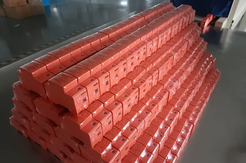
VIOX SPD-VERKSTAD

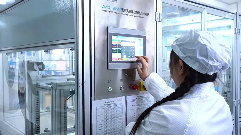
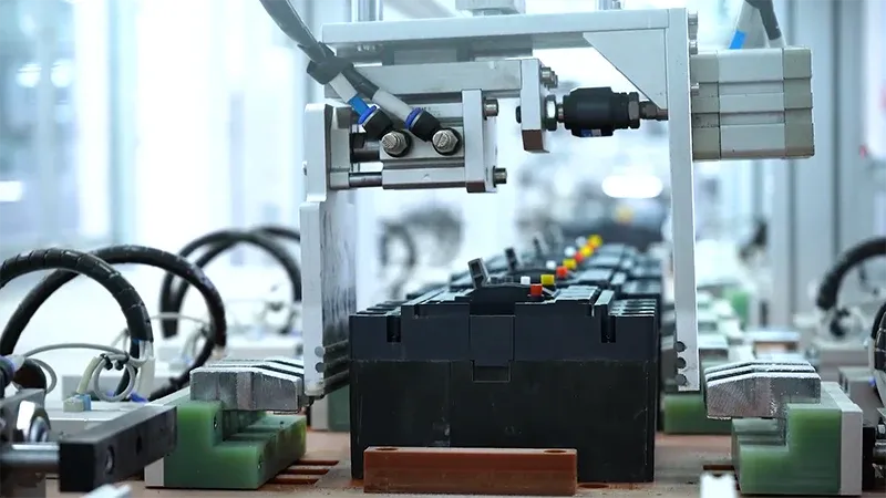
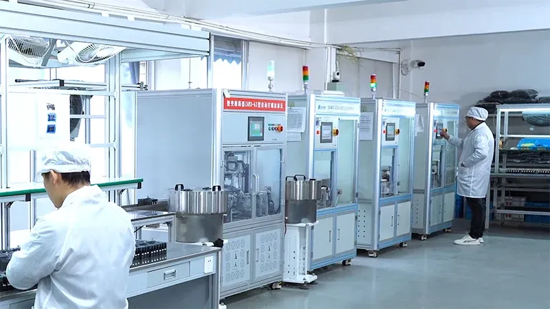
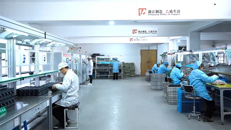

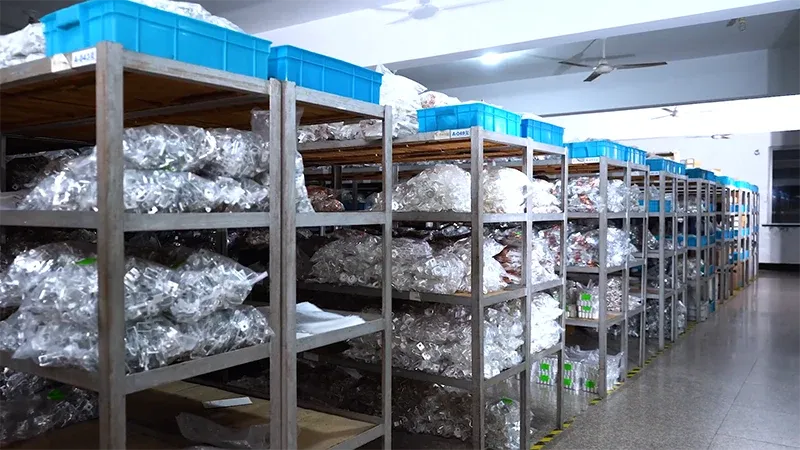
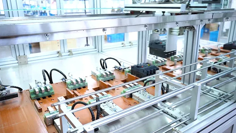
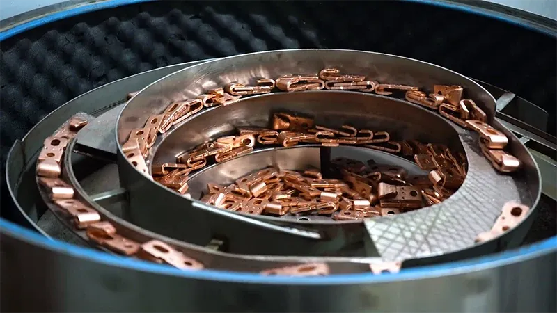
Mer än bara en SPD-tillverkare
På VIOX går vi bortom tillverkning av SPD genom att erbjuda en uppsättning mervärdestjänster skräddarsydda för att möta dina projektbehov. Vårt engagemang för excellens säkerställer att varje kund får personlig uppmärksamhet, expertvägledning och smidigt stöd under hela sin resa med oss.

Service Konsultation
Oavsett om dina SPD-krav är enkla eller komplexa, erbjuder vårt team expertråd och teknisk konsultation. För mer komplicerade projekt erbjuder vi djupgående teknisk support för att säkerställa optimalt produktval och tillämpning, vilket garanterar säkerhet och effektivitet i dina elsystem.
Rekommendationer för produkter
Är du osäker på vilken SPD som passar ditt system? Våra specialister ger kostnadsfria, anpassade rekommendationer baserade på dina specifika drifts- och miljökrav, vilket säkerställer att du får den perfekta lösningen för dina elektriska skyddsbehov.

Logistikstöd
Om du saknar en pålitlig speditör kan vi ordna transport från vår fabrik till din projektplats utan extra kostnad. Vårt logistikteam ser till att leveranserna sker i rätt tid och på ett säkert sätt så att ditt projekt kan hålla tidsplanen och minimera stillestånd och förseningar.
Stöd för installation
Behöver du hjälp med installationen? Vårt tekniska team finns tillgängligt för att svara på dina frågor eller ge praktisk support. För större projekt kan vi till och med skicka en ingenjör till din plats för assistans på plats, vilket säkerställer att dina SPD:er installeras korrekt och fungerar smidigt i ditt elnät.
Vanliga Frågor Och Svar
Vi har sammanställt några vanliga frågor från våra kunder. Om din fråga inte finns med här är vår kundtjänst alltid tillgänglig för att hjälpa till. Vi vill gärna prata med dig.
Hur kan jag få en offert på SPD-produkter?
För att få en offert för vår SPD produkter, kontakta vår kundtjänst. Vi är tillgängliga dygnet runt. Ange bara detaljerna för din beställning, såsom typ (DC SPD eller AC SPD), spänningsklassning, strömklassning och kvantitet. Vi guidar dig genom hela beställningsprocessen.
Vad är din MOQ för SPD-beställningar?
Vi har en låg MOQ eller minsta orderkvantitet. Du kan beställa så lite som en enhet, och vi kommer att leverera enligt dina specifikationer.
Vad är handläggningstiden för min SPD-beställning?
Standardleveranstiden för vår SPD Leveranstiden för produkter är 7 till 10 arbetsdagar. Leveranstiden kan förlängas med upp till 15 arbetsdagar på grund av transport. För specialbeställningar eller bulkbeställningar kan vi diskutera handläggningstiden innan vi slutför din beställning.
Kan jag få ett prov innan jag lägger beställningen?
Ja, vi tillhandahåller SPD prover för utvärdering och godkännande. Att skapa prover tar vanligtvis 3 till 7 arbetsdagar.
Kan ni tillverka anpassade SPD-produkter?
Ja, vi erbjuder kundanpassade SPD lösningar. Berätta dina krav för oss, så kommer vår expertkundtjänst att arbeta med dig genom designprocessen.
Vilken garanti har ni för SPD-produkter?
Vi erbjuder 3 års garanti på alla SPD produkter vi producerar. Detta säkerställer att vi levererar högkvalitativa produkter. Varje produkt testas noggrant före leverans.
Allt om SPD
Vad är SPD?
Ett överspänningsskydd (SPD) är en viktig elektrisk säkerhetsanordning som är utformad för att skydda mot spänningstoppar och elektriska transienter. Den fungerar genom att tillhandahålla en lågimpedansväg för stötströmmar och avleda dem bort från känslig utrustning. När SPD detekterar en spänningsstöt som överstiger den normala driftsnivån, leder den snabbt överskottsenergin till jord, vanligtvis inom nanosekunder.
SPD:er är viktiga komponenter i moderna elsystem och skyddar dyr utrustning från skador orsakade av blixtnedslag, strömbrytare och belastningsvariationer. I takt med att elsystem blir mer sofistikerade och känsliga fortsätter vikten av korrekt överspänningsskydd att öka.
SPD vs. andra skyddsenheter
Att förstå de olika typerna av överspänningsskydd är avgörande för att välja rätt skydd för din applikation:
- AC-hastighetsfördelning: Ger skydd mot växelströmsspänningstoppar och transienter i växelströmssystem
- DC-hastighetsfördelning: Speciellt utformad för likströmssystem och solcellsapplikationer, för att skydda solcellsinstallationer
- Typ 1 SPD: Blixtskydd för huvudfördelningscentraler och serviceingångar
- Typ 2 SPD: Överspänningsskydd för underfördelnings- och slutkretsar
- Typ 1+2 SPD: Kombinerat skydd som erbjuder både blixt- och överspänningsskydd i en enda enhet
- Typ 3 SPD: Skydd vid användningsstället för enskild utrustning och känsliga enheter
Hur SPD:er fungerar
Den grundläggande principen bakom SPD-drift är spänningsbegränsande teknik. SPD:er övervakar kontinuerligt det elektriska systemets spänningsnivåer och reagerar omedelbart på onormala förhållanden:
Detektionsmekanism: Metalloxidvaristorer (MOV) eller gasurladdningsrör detekterar spänningsvariationer över normala driftsnivåer. Dessa komponenter har variabel resistans som minskar dramatiskt när de utsätts för höga spänningar.
Aktiveringssvar: När spänningen överstiger skyddsnivån, SPD leder elektricitet och skapar en lågimpedansväg till jord. Denna åtgärd avleder den farliga stötströmmen bort från skyddad utrustning.
Energiomledning: Överskottsenergi leds säkert till jord, vilket skyddar ansluten utrustning från skador. SPDåtergår automatiskt till sitt högohmiga tillstånd när överspänningen är över.
Självskydd: Modern SPD:er inkludera termiska frånkopplingsanordningar som säkert kopplar bort enheten om den skadas, vilket förhindrar brandrisker och bibehåller systemets integritet.
Viktiga tekniska parametrar
- Maximal kontinuerlig driftspänning (Uc): Högsta spänning som SPD:n tål kontinuerligt
- Nominell urladdningsström (In): Ström som SPD:n kan hantera under testning
- Maximal urladdningsström (Imax): Högsta ström som SPD:n säkert kan leda
- Spänningsskyddsnivå (upp): Maximal spänning som uppträder över SPD-terminalerna
- Svarstid: Tid mellan överspänningsdetektering och aktivering av skydd
SPD-valguide
När du väljer rätt AC- eller DC-strömförsörjningsenhet för din applikation, tänk på dessa viktiga faktorer:
- Systemets spänning: Välj en SPD med lämplig spänningsklassning för ditt system
- Nuvarande betyg: Välj baserat på förväntade stötströmsnivåer i din applikation
- Skyddstyp: Typ 1 för åskskydd, Typ 2 för överspänningsskydd, Typ 1+2 för kombinerat skydd
- Ansökan: AC-spolar för växelströmssystem, DC-spolar för likström och solcellsapplikationer
- Miljöförhållanden: Tänk på driftstemperatur, luftfuktighet och installationsplats
Rådgör alltid med en kvalificerad elektriker för att säkerställa att SPD:n uppfyller dina specifika elsystemkrav och lokala föreskrifter.
Bästa praxis för SPD-installation
Korrekt installation är avgörande för effektiv SPD-prestanda:
Platsval: Installera SPD:er så nära den utrustning som skyddas som möjligt. Minimera ledningslängden för att minska spänningsfallet vid överspänningar.
Jordning: Säkerställ en stabil, lågimpedansanslutning till jordningssystemet. Dålig jordning kan orsaka SPDskyddet ineffektivt.
Ledlängd: Hålla SPD Anslutningskablarna ska vara så korta som möjligt (vanligtvis kortare än 30 cm). Längre ledningar minskar skyddets effektivitet.
Säkerhetskopieringsskydd: Installera lämpliga säkringar eller kretsbrytare för att skydda SPD enheter från överströmsförhållanden.
Flera nivåer: Använd samordnad SPD skydd på flera nivåer (serviceingång, distributionspaneler, utrustningsnivå) för heltäckande skydd.
SPD-underhåll och testning
Regelbundet underhåll säkerställer optimal SPD-prestanda:
Visuell inspektion: Kontrollera varje månad för fysiska skador, korrosion eller lösa anslutningar. Leta efter tecken på termisk stress eller försämring.
Statusindikatorer: Övervaka SPD Statusindikatorer (vanligtvis grönt för normalt, rött för fel). Byt ut trasiga enheter omedelbart.
Elektrisk provning: Utför årlig elektrisk kontroll för att verifiera SPD funktionalitet och skyddsnivåer. Använd lämplig testutrustning avsedd för SPD testning.
Dokumentation: Förvara register över SPD installation, testning och utbyte för att spåra systemets prestanda och planera underhåll.
Ersättningskriterier: Ersätta SPD:er som visar tecken på skador, misslyckas med testning eller når slutet av sin livslängd enligt tillverkarens anvisningar.
SPD-applikationer och industrier
SPD:er är viktiga i många tillämpningar:
Solcellssystem: DC-sPD:er skydda dyr solcellsutrustning från blixtar och överspänningar. Både strängnivåskydd och skydd för kombinationsboxar krävs vanligtvis.
Kommersiella byggnader: AC-spån skydda känslig utrustning som datorer, VVS-system och belysningskontroller från spänningstransienter.
Industriella anläggningar: Skydda motorer, drivenheter, PLC:er och processkontrollutrustning från överspänningar som kan orsaka produktionsavbrott.
Bostadsapplikationer: Hela huset SPD:er skydda apparater, elektronik och elektriska system från spänningsöverspänningar.
Telekommunikation: Specialiserad SPD:er skydda kommunikationsutrustning från blixtar och störningar i elsystemet.
Datacenter: Avgörande för att skydda servrar, nätverksutrustning och UPS-system från problem med elkvaliteten.
Framtiden för SPD-teknik
SPD-branschen fortsätter att utvecklas med avancerad teknik:
Smarta SPD:er: Integrering av övervaknings- och kommunikationsfunktioner möjliggör fjärrövervakning av status och förebyggande underhåll.
Förbättrade material: Utveckling av nya varistormaterial med förbättrad prestanda och längre livslängd.
Modulära konstruktioner: Utbytbara överspänningsmoduler minskar underhållskostnaderna och förbättrar systemets tillförlitlighet.
IoT-integration: SPD:er med funktioner för sakernas internet tillhandahåller övervakning och dataanalys i realtid.
Grön teknologi: Miljövänlig SPD design med minskad miljöpåverkan och förbättrad återvinningsbarhet.
Rådfråga alltid en behörig elektriker för att säkerställa SPD uppfyller dina specifika krav på elsystemet och lokala föreskrifter. SPD Val och installation är avgörande för effektivt överspänningsskydd och elsäkerhet.
Yueqing: SPD-tillverkningscentrum
Yueqing, en stad på länsnivå i Zhejiang-provinsen, Kina, är erkänd som en av världens största tillverkningshubbar för elektriska skyddsanordningar, inklusive överspänningsskydd (SPD). Denna stad i Wenzhou-regionen, känd som "Kinas elhuvudstad", har blivit framträdande tack vare sitt omfattande nätverk av tillverkare av elektriska komponenter och avancerade produktionskapacitet.
Stadens dominans i SPD-tillverkning drivs av sin höga koncentration av specialiserade fabriker, såsom VIOX Electric, som fokuserar på att producera högkvalitativa elektriska skyddsanordningar. Yueqing har toppmoderna tillverkningsanläggningar med automatiserade produktionslinjer och strikta kvalitetskontrollåtgärder. Närheten till stora transportknutpunkter som Wenzhou, Ningbo och Shanghais hamnar säkerställer effektiv global distribution. Dessutom betonar branschen forskning och utveckling och erbjuder skräddarsydda OEM/ODM-lösningar samtidigt som de följer internationella standarder som UL-, CE-, CSA-, IEC- och RoHS-certifieringar.
Begär ett VIOX SPD-prov
VIOX Electric är redo att hjälpa dig med dina OEM-avledarbehov. Vi erbjuder högkvalitativa och kostnadseffektiva lösningar.