
A trip curve is a graphical representation that shows the relationship between current magnitude and the time it takes for a strømbryter to trip and interrupt the circuit. This essential electrical engineering tool helps engineers select appropriate protective devices, coordinate protection systems, and ensure electrical safety in residential, commercial, and industrial applications.
Understanding trip curves is crucial for anyone working with electrical systems, as they directly impact equipment protection, system reliability, and personnel safety. This comprehensive guide will equip you with the knowledge to read, interpret, and apply trip curves effectively in your electrical projects.
What Are Trip Curves? Essential Definitions
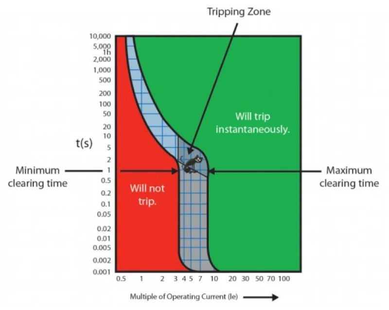
A turkurve (also called a time-current curve or characteristic curve) is a logarithmic graph that displays how long it takes for a circuit breaker to open under different fault current conditions. The horizontal axis represents current (in amperes), while the vertical axis shows time (in seconds).
Key Components of Trip Curves:
- Current Axis (X-axis): Shows fault current magnitude in amperes or multiples of rated current
- Time Axis (Y-axis): Displays tripping time in seconds on a logarithmic scale
- Trip Band: The shaded area between minimum and maximum trip times
- Instantaneous Trip Point: The current level where immediate tripping occurs
- Thermal Region: Lower current range where bimetallic elements provide protection
- Magnetic Region: Higher current range where magnetic elements provide rapid protection
Trip Curve Types: Complete Comparison Guide
Different circuit breakers utilize various trip curve characteristics to match specific protection requirements. Here’s a comprehensive comparison of standard trip curve types:
| Kurvetype | Søknad | Kjennetegn | Typical Use |
|---|---|---|---|
| Type B | Bolig/Lett næringsbygg | Trips at 3-5x rated current | Lighting, outlets, small motors |
| Type C | Kommersiell/industriell | Trips at 5-10x rated current | Motors, transformers, fluorescent lighting |
| Type D | Industrial/High Inrush | Trips at 10-20x rated current | Large motors, welding equipment |
| Type K | Motorbeskyttelse | Trips at 8-12x rated current | Motorstyringskretser |
| Type Z | Electronic Protection | Trips at 2-3x rated current | Sensitivt elektronisk utstyr |
⚠️ SAFETY WARNING: Always consult NEC (National Electrical Code) and local electrical codes when selecting circuit breakers. Incorrect selection can lead to equipment damage, fire hazards, or personal injury.
How to Read Trip Curves: Step-by-Step Process
Step 1: Identify the Current Level
- Locate your fault current value on the horizontal axis
- Use either actual amperes or multiples of rated current
Step 2: Find the Intersection Point
- Draw a vertical line from your current value upward
- Note where it intersects with the trip curve band
Step 3: Determine Trip Time
- Read the corresponding time value on the vertical axis
- Account for the trip band range (minimum to maximum)
Step 4: Consider Environmental Factors
- Ambient temperature affects trip times
- Altitude and humidity can influence performance
- Account for tolerance variations (typically ±20%)
Trip Curve Applications and Use Cases
Bruksområder i boliger:
- Belysningskretser: Type B curves provide appropriate protection for standard incandescent and LED lighting
- Outlet Circuits: Type B or C curves protect against overloads and short circuits
- Small Appliances: Type C curves handle motor starting currents
Kommersielle applikasjoner:
- Kontorbygg: Type C curves for general distribution and motor loads
- Retail Spaces: Type B for lighting, Type C for HVAC equipment
- Datasentre: Type Z curves for sensitive electronic equipment protection
Industrielle bruksområder:
- Motorstyringssentraler: Type D curves for high-inrush motors
- Welding Operations: Type D curves handle high starting currents
- Produksjonsutstyr: Custom curves for specialized machinery
Circuit Breaker Selection Criteria
Primary Selection Factors:
- Load Type Analysis
- Resistive loads: Lower trip curves (Type B)
- Inductive loads: Higher trip curves (Type C, D)
- Electronic loads: Specialized curves (Type Z)
- Fault Current Calculations
- Maximum available fault current
- Koordinering med oppstrøms enheter
- Krav til selektiv koordinering
- Overholdelse av lover og regler
- NEC Article 240 requirements
- Local electrical code provisions
- Industry standards (IEEE, NEMA)
💡 EXPERT TIP: Use coordination software to verify that your trip curve selection provides proper selective coordination throughout your electrical system.
Common Trip Curve Problems and Solutions
Problem: Nuisance Tripping
- Forårsake: Trip curve too sensitive for load type
- Løsning: Select higher trip curve (B to C, C to D)
- Forebygging: Proper load analysis during design
Problem: Inadequate Protection
- Forårsake: Trip curve too high for application
- Løsning: Lower trip curve selection with load compatibility check
- Forebygging: Comprehensive fault current study
Problem: Coordination Issues
- Forårsake: Overlapping trip curves between devices
- Løsning: Implement time-current coordination study
- Forebygging: Professional coordination analysis
Professional Standards and Compliance
Required Certifications:
- UL 489: Standard for molded case circuit breakers
- IEEE C37.17: Standard for trip devices
- NEMA AB-1: Standards for molded case circuit breakers
Code Requirements:
- NEC Article 240: Overcurrent protection requirements
- NEC 240.86: Series combination ratings
- Local Amendments: Regional code modifications
Quick Reference: Trip Curve Selection Guide
For Residential Use:
- General lighting: Type B
- Small motors (1/2 HP or less): Type C
- Electric heat: Type B or C
For Commercial Use:
- Fluorescent lighting: Type C
- Motor loads: Type C or D
- Electronic equipment: Type Z
For Industrial Use:
- Large motors: Type D
- Welding equipment: Type D
- Sensitive controls: Type Z
Ofte stilte spørsmål
Q: How do I determine the right trip curve for my application?
A: Analyze your load type, calculate fault currents, and consult NEC requirements. For motor loads, use Type C or D curves. For lighting and general use, Type B is typically appropriate.
Q: Can I use a higher trip curve than required?
A: While possible, this may reduce protection sensitivity and create coordination issues. Always verify that higher curves still provide adequate protection for your conductors and equipment.
Q: What happens if I select the wrong trip curve?
A: Wrong selection can cause nuisance tripping (too sensitive) or inadequate protection (not sensitive enough), potentially leading to equipment damage or safety hazards.
Q: How do temperature changes affect trip curves?
A: Higher temperatures cause faster tripping, while lower temperatures delay tripping. Standard curves are based on 40°C ambient temperature.
Q: Do I need different trip curves for different phases?
A: No, all phases of a multi-pole breaker use the same trip curve. However, different circuits may require different trip curves based on their specific loads.
Faglige anbefalinger
When to Consult a Professional:
- Complex coordination studies
- High-fault current applications
- Critical system protection
- Verifisering av samsvar med koden
Best Practices:
- Always perform load analysis before selection
- Use manufacturer’s coordination software
- Document all calculations and selections
- Regular testing and maintenance of protective devices
⚠️ SAFETY REMINDER: Electrical work involving circuit breakers should only be performed by qualified electricians following proper safety procedures and code requirements.
Understanding trip curves is fundamental to electrical system design and safety. By following this guide and consulting with qualified professionals when needed, you can ensure proper protection device selection for your specific applications while maintaining code compliance and system reliability.
Relatert
Hva er en støpt sikringsbryter (MCCB)
Hvordan vite om sikringsbryteren er dårlig
How Circuit Breaker Poles Affect Voltage
Hva er forskjellen mellom MCB, MCCB, RCB, RCD, RCCB og RCBO? Fullfør 2025
