
Pendahuluan: Klik yang Tidak Pernah Datang
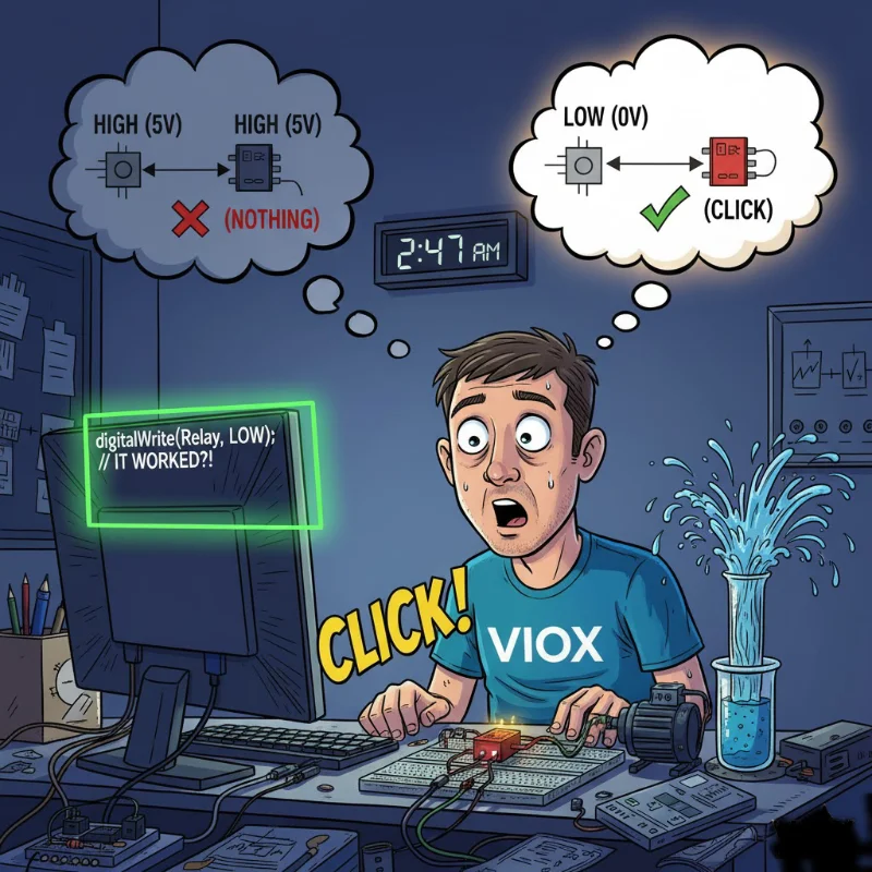
PUKUL 2:47 PAGI. Anda sudah melakukan ini selama tiga jam.
Proyek Arduino Anda terlihat sempurna. Modul relai ada di papan tempat memotong roti Anda, disambungkan persis seperti yang ditunjukkan tutorial. Anda telah memeriksa tiga kali: VCC ke 5V, GND ke GND, IN1 ke pin digital 7. Kode dikompilasi. Anda mengunggahnya. Pin 7 menjadi TINGGI.
Tidak ada.
Tidak ada klik. Tidak ada LED. Relai hanya ... duduk di sana. Mengejekmu.
Anda menukar modul relai. Masih belum ada. Anda mencoba pin Arduino yang berbeda. Tidak. Anda menulis ulang kode untuk memastikan Anda menyetel pin dengan benar. Ini menegaskan: TINGGI. 5 volt. Multimeter setuju.
Dan relay masih tidak akan memicu.
Kemudian, karena putus asa atau rasa ingin tahu yang disebabkan oleh kafein, Anda mengubah satu baris kode:
digitalWrite(relayPin, LOW); / / Berubah dari TINGGIKlik.
Relai aktif. LED menyala. Pompa Anda mulai bekerja. Semuanya bekerja.
Tunggu ... apa? Relai terpicu saat Anda menyetel pin RENDAH, bukan TINGGI? Itu mundur. Itu salah. Itu dia—
Sebenarnya, begitulah cara kerja relai pemicu tingkat rendah. Dan begitu Anda memahami alasannya, Anda akan menyadari bahwa itu tidak aneh—sebenarnya itu adalah desain yang lebih cerdas.
Biar kujelaskan.
Apa arti sebenarnya dari "Pemicu Tingkat Rendah" (dalam bahasa Inggris sederhana)
Relai pemicu tingkat rendah aktif ketika pin kontrolnya menerima sinyal RENDAH (0V/GND) alih-alih sinyal TINGGI (5V).
Dalam istilah logika digital:
- Sinyal RENDAH (0V) = Relai HIDUP
- Sinyal TINGGI (5V) = Relai MATI
Ini juga disebut logika aktif-rendah atau logika terbalik.
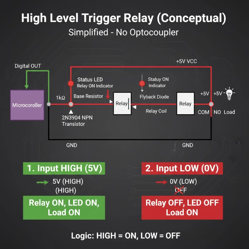
Bandingkan ini dengan relai pemicu tingkat tinggi:
- Sinyal TINGGI (5V) = Relay MENYALA
- Sinyal RENDAH (0V) = Relai MATI
Itu saja. Itulah perbedaan intinya. Tapi di sinilah hal itu menjadi menarik: mengapa modul relai menggunakan pendekatan yang tampaknya terbelakang ini?
Mengapa Modul Relai Menggunakan Pemicu Tingkat Rendah (Rahasianya Adalah optocoupler)
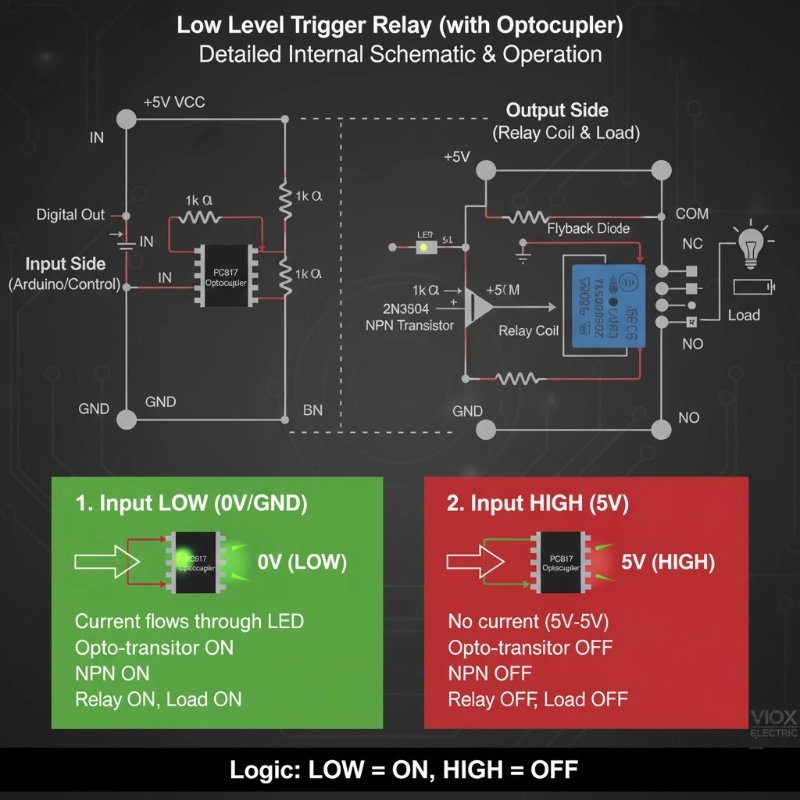
Sebagian besar modul relai tidak hanya memiliki relai—mereka memiliki rangkaian driver lengkap yang terpasang. Inti dari rangkaian ini adalah optocoupler (juga disebut opto-isolator), biasanya PC817 atau sejenisnya.
Desain Sirkuit Optocoupler
Inilah yang sebenarnya ada di dalam modul relai Anda:
Sisi Input (Sinyal Kontrol):
- Pin digital Arduino Anda terhubung ke "DALAM"
- IN terhubung ke LED di dalam optocoupler (melalui resistor)
- Katoda LED terhubung ke GND
Sisi Keluaran (Kumparan Relai):
- Sebuah fototransistor (di dalam optocoupler) mendeteksi cahaya LED
- Transistor ini menggerakkan transistor NPN (seperti 2N3904)
- Transistor NPN memberi energi pada koil relai
Detail Penting: LED optocoupler disambungkan antara VCC dan pin IN. Ini adalah kunci untuk memahami pemicu tingkat rendah.
Cara Kerja Pemicu Tingkat Rendah
Saat DALAM pin = TINGGI (5V):
- Perbedaan tegangan pada LED = 5V-5V = 0V
- Tidak ada arus yang mengalir melalui LED
- LED tetap MATI
- Fototransistor tetap MATI
- Relay coil tidak mendapat daya
- Relai tetap MATI
Saat DALAM pin = RENDAH (0V / GND):
- Perbedaan tegangan pada LED = 5V-0V = 5V
- Arus mengalir melalui LED (dibatasi oleh resistor)
- Lampu LED menyala
- Fototransistor menyala (ON)
- Transistor NPN menghantar
- Kumparan relai memberi energi
- Relay berbunyi "klik" menyala (ON)
“Momen Aha”: Rangkaian menarik arus dari VCC ke GND melalui pin IN. Ketika pin Arduino Anda LOW, ia menyediakan jalur ke ground, menyelesaikan rangkaian. Ketika HIGH, tidak ada perbedaan tegangan, jadi tidak ada arus yang mengalir.
Mengapa Desain Ini Sebenarnya Brilian
- Perilaku Aman-Gagal (Fail-Safe): Jika kabel kontrol Anda putus atau terputus, pin IN secara efektif mengambang HIGH (ditarik ke atas secara internal oleh jaringan resistor). Ini menjaga relay dalam keadaan OFF secara default—lebih aman daripada menyala (ON) secara tidak sengaja.
- Perlindungan Terhadap Pin Mengambang: Selama boot-up Arduino, pin berada dalam keadaan tidak terdefinisi selama beberapa milidetik. Dengan pemicu level rendah, ini biasanya menghasilkan relay OFF (aman) daripada relay ON (berpotensi berbahaya untuk beban berdaya tinggi).
- Penarikan Arus Lebih Rendah dari Mikrokontroler: Ketika relay OFF (keadaan paling umum untuk banyak aplikasi), pin mikrokontroler HIGH dan memasok hampir nol arus. Ketika Anda perlu mengaktifkan relay, pin menjadi LOW dan menyerap arus—yang biasanya lebih baik ditangani oleh pin mikrokontroler daripada memasok.
- Kompatibilitas 3.3V: ESP32 dan perangkat 3.3V serupa kesulitan untuk menggerakkan modul relay 5V secara andal dalam konfigurasi level tinggi. Tetapi dalam mode level rendah, pin 3.3V dapat menyerap arus ke ground dengan baik, bahkan ketika VCC adalah 5V. Ini membuat modul pemicu level rendah lebih kompatibel secara universal.
Tip Pro: Inilah mengapa sebagian besar modul relay komersial secara default menggunakan pemicu level rendah—ini adalah desain yang lebih kuat, kompatibel, dan aman-gagal.
Cara Menyambungkan Relay Pemicu Level Rendah (Langkah demi Langkah)
Pengkabelan Dasar untuk Arduino Uno (Logika 5V)
Koneksi Daya:
- Relay VCC → Arduino 5V
- Relay GND → Arduino GND
Sinyal Kontrol:
- Relay IN → Pin Digital Arduino (mis., Pin 7)
Contoh Kode:
const int relayPin = 7;Apa yang Terjadi:
- HIGH (5V) menjaga relay OFF
- LOW (0V) menyalakan relay ON
Pengkabelan untuk ESP32 (Logika 3.3V)
ESP32 mengeluarkan 3.3V pada HIGH, yang dapat menyebabkan masalah dengan beberapa modul relay 5V. Berikut adalah pendekatan yang andal:
Koneksi Daya:
- Relay VCC → Catu daya 5V eksternal (atau pin 5V ESP32 jika menggunakan daya USB)
- Relay GND → Ground bersama dengan ESP32
Sinyal Kontrol:
- Relay IN → Pin GPIO ESP32 (mis., GPIO 23)
Contoh Kode:
const int relayPin = 23; // ESP32 GPIO23Mengapa Ini Bekerja dengan 3.3V:
Ketika pin ESP32 menjadi LOW (0V), ia menyediakan jalur ground. LED optocoupler ditenagai oleh catu daya VCC 5V, sehingga penurunan tegangan 5V penuh terjadi di seluruh LED—cukup untuk menyalakannya dan memicu relay.
Tip Pro: Jika modul relay Anda memiliki jumper untuk JD-VCC (daya relay) yang terpisah dari VCC (daya logika), lepaskan jumper dan beri daya JD-VCC dari 5V sambil menjaga VCC pada 3.3V. Ini memberikan isolasi lengkap dan keandalan yang lebih baik dengan mikrokontroler 3.3V.
Level Rendah vs Level Tinggi: Mana yang Harus Anda Pilih?
Sebagian besar modul relay dilengkapi dengan jumper atau sakelar untuk memilih antara mode pemicu level rendah dan level tinggi. Berikut adalah kapan menggunakan masing-masing:
Pilih Pemicu Level Rendah Ketika:
- ✅ Menggunakan mikrokontroler 3.3V (ESP32, ESP8266, Raspberry Pi)
- ✅ Anda menginginkan perilaku aman-gagal (relay default OFF jika kabel kontrol gagal)
- ✅ Bekerja dengan modul relay yang tidak dikenal atau belum diuji (ini adalah mode yang lebih umum/kompatibel)
- ✅ Aplikasi Anda membutuhkan beban untuk OFF sebagian besar waktu
- ✅ Anda seorang pemula (kemungkinan kecil mengalami masalah kompatibilitas)
Contoh Aplikasi:
- Otomasi rumah (lampu OFF secara default)
- Sistem alarm (sirene OFF secara default)
- Kontrol pompa (pompa OFF kecuali dipicu secara aktif)
- Interlock keselamatan (peralatan dinonaktifkan kecuali diaktifkan secara aktif)
Pilih Pemicu Level Tinggi Ketika:
- ✅ Anda membutuhkan relay ON selama reset/boot Arduino (kasus penggunaan yang jarang tetapi spesifik)
- ✅ Bekerja dengan beban normally-closed (NC) di mana Anda menginginkan perilaku terbalik
- ✅ Logika kode Anda lebih sederhana dengan “HIGH = ON” (preferensi pribadi)
- ✅ Berinteraksi dengan sistem kontrol active-high (PLC, pengontrol industri)
Contoh Aplikasi:
- Pencahayaan darurat (tetap ON selama pemadaman listrik)
- Kipas pendingin (ON secara default untuk keselamatan)
- Sistem pemutus baterai (persyaratan aman-gagal spesifik)
Kebenaran yang Jujur: Untuk 95% proyek Arduino/ESP32, pemicu level rendah adalah pilihan yang lebih baik.
Ini lebih kompatibel, lebih andal, dan lebih aman. Jangan terlalu memikirkannya.
Kesalahan Umum dan Cara Memperbaikinya
Kesalahan #1: “Relay Saya Selalu ON!”
Gejala: Relay berbunyi "klik" ON segera setelah Anda menghidupkan Arduino, bahkan sebelum kode Anda berjalan.
Penyebab: Selama boot, pin Arduino berada dalam keadaan tidak terdefinisi (mengambang). Jika pin mengambang LOW, relay akan terpicu.
Perbaikan:
void setup() {Mengatur keadaan pin sebelum mengaturnya sebagai OUTPUT memastikan pin dimulai dalam keadaan OFF.
Kesalahan #2: “Berfungsi... Tapi Kemudian Memicu Secara Acak”
Gejala: Relay kadang-kadang berbunyi "klik" ON (hidup) padahal seharusnya tidak, terutama dengan kabel panjang atau lingkungan yang bising.
Penyebab: Derau listrik atau kondisi pin yang mengambang.
Perbaikan #1 – Tambahkan Resistor Pull-Up Eksternal:
Hubungkan resistor 10kΩ antara pin IN dan VCC. Ini menjaga IN tetap HIGH (relay OFF/mati) ketika Arduino Anda tidak secara aktif menariknya ke LOW (rendah).
Perbaikan #2 – Aktifkan Pull-Up Internal:
void setup() {Kesalahan #3: “Relay ESP32 Tidak Berbunyi ”Klik' Secara Konsisten”
Gejala: Relay berfungsi kadang-kadang, gagal di lain waktu. LED pada board relay menyala tetapi relay tidak berbunyi "klik".
Penyebab: Arus yang tidak mencukupi dari GPIO 3.3V untuk menggerakkan LED optocoupler dengan andal.
Perbaikan – Gunakan Modul Relay 3.3V Khusus:
Cari modul relay yang secara khusus dinilai untuk tegangan pemicu 3.3V (bukan hanya kompatibel 3.3V). Ini memiliki sirkuit optocoupler yang dioptimalkan dengan persyaratan tegangan maju LED yang lebih rendah.
Atau – Beri Daya VCC Modul Relay pada 5V:
Meskipun ESP32 adalah 3.3V, Anda dapat memberi daya VCC modul relay dari 5V (pin 5V ESP32 atau catu daya eksternal) sementara GPIO ESP32 menenggelamkan arus ke GND. Ini memberikan arus LED yang lebih kuat melalui optocoupler.
Kesalahan #4: “Saya Salah Memasang Jumper”
Gejala: Perilaku relay berlawanan dengan yang diharapkan oleh kode Anda.
Penyebab: Modul relay memiliki jumper yang diatur ke mode pemicu level tinggi.
Perbaikan:
Cari jumper 3-pin di dekat terminal sekrup, biasanya berlabel:
- H (Pemicu level Tinggi)
- COM (Umum)
- L (Pemicu level Rendah)
Pindahkan jumper untuk menghubungkan COM dan L untuk mode pemicu level rendah.
Jika Tidak Ada Jumper: Beberapa modul relay diperbaiki hanya pada level rendah. Periksa deskripsi produk atau uji: jika LOW menghidupkannya (ON), itu adalah pemicu level rendah.
Kesalahan #5: “Relay Berbunyi ”Klik' Tetapi Beban Tidak Menyala”
Gejala: Anda mendengar relay berbunyi "klik", LED menyala, tetapi lampu/motor/pompa Anda tidak aktif.
Penyebab: Ini bukan masalah pemicu—ini adalah masalah perkabelan di sisi tegangan tinggi.
Perbaikan – Periksa Perkabelan Beban:
COM (Umum) terhubung ke sumber daya (mis., 12V+ atau saluran AC)
NO (Biasanya Terbuka) terhubung ke terminal positif beban
Negatif beban kembali ke negatif sumber daya
Untuk beban AC (seperti lampu):
- COM ke kabel panas AC
- NO ke lampu
- Terminal lampu lainnya ke netral AC
Catatan Keamanan Kritis:
Jika bekerja dengan tegangan listrik AC (110V/220V), matikan daya di pemutus sirkuit sebelum melakukan perkabelan. Jika Anda tidak nyaman dengan perkabelan AC, gunakan teknisi listrik yang berkualifikasi.
Aplikasi Praktis: Kapan Anda Sebenarnya Membutuhkan Relay Pemicu Level Rendah
1. Proyek Otomasi Rumah
Skenario: Stopkontak pintar yang dikendalikan ESP32 untuk lampu.
Mengapa Pemicu Level Rendah:
- ESP32 adalah 3.3V (kompatibilitas lebih baik)
- Lampu harus OFF (mati) secara default (aman jika terjadi kegagalan)
- Pemicu acak selama koneksi ulang WiFi akan mengganggu
Implementasi:
const int relayPin = 23;2. Pengontrol Irigasi Taman
Skenario: Pompa air berwaktu Arduino untuk bedengan taman.
Mengapa Pemicu Level Rendah:
- Pompa OFF (mati) secara default (mencegah banjir jika Arduino crash)
- Kabel panjang ke relay luar ruangan (kekebalan terhadap derau dengan pull-up)
- Aman jika terjadi kegagalan: kabel putus = tidak ada air = tanaman bertahan hidup
Implementasi:
void waterGarden(int minutes) {3. Manajemen Daya Printer 3D
Skenario: Secara otomatis menghidupkan printer sebelum pekerjaan pencetakan, mematikan saat selesai.
Mengapa Pemicu Level Rendah:
- Printer OFF (mati) saat tidak mencetak (menghemat daya, mengurangi risiko kebakaran)
- OctoPrint (Raspberry Pi) menggunakan GPIO 3.3V
- Aman jika terjadi kegagalan: sistem crash = printer tetap OFF (mati)
4. Pengontrol Akuarium
Skenario: Kontrol pemanas berbasis suhu dengan Arduino.
Mengapa Pemicu Level Rendah:
- Pemanas OFF (mati) secara default (mencegah ikan terlalu panas jika sensor gagal)
- Kompatibilitas Arduino 5V atau ESP32 3.3V
- Beberapa relay (lampu, filter, pemanas) semua membutuhkan perilaku aman jika terjadi kegagalan yang terkoordinasi
Apa Artinya Ini untuk Proyek Anda Berikutnya
Relay pemicu level rendah tidak aneh—itu adalah standar. Setelah Anda menghayati logika (“LOW = ON, HIGH = OFF”), itu menjadi kebiasaan. Dan manfaatnya—perilaku aman jika terjadi kegagalan, kompatibilitas yang lebih baik, kekebalan terhadap derau—menjadikannya pilihan cerdas untuk sebagian besar proyek Arduino dan ESP32.
Panduan Keputusan Cepat:
Gunakan Relay Pemicu Level Rendah Jika:
- ✅ Anda menggunakan ESP32, ESP8266, atau mikrokontroler 3.3V apa pun
- ✅ Beban Anda harus dalam keadaan MATI secara default (pompa, pemanas, alarm)
- ✅ Anda menginginkan perilaku fail-safe (kabel putus = relay MATI)
- ✅ Anda sedang membuat proyek pemula
- ✅ Anda menghargai kompatibilitas daripada berdebat dengan level logika
Gunakan Relay Pemicu Level Tinggi Jika:
- ✅ Aplikasi spesifik Anda memerlukan relay ON selama boot mikrokontroler
- ✅ Anda berinteraksi dengan sistem kontrol industri (PLC)
- ✅ Anda memiliki alasan yang sangat spesifik (dan Anda tahu apa itu)
Pro Tip:
Saat membeli modul relay, cari yang mendukung pemicuan level tinggi dan rendah dengan jumper. Ini memberi Anda fleksibilitas untuk memilih mode terbaik untuk setiap proyek.
Memilih Modul Relay yang Tepat
Saat berbelanja modul relay, inilah yang perlu diperiksa:
Untuk Arduino Uno / Mega (5V):
- Tegangan operasi: 5V DC
- Tegangan pemicu: Kompatibel 5V
- Arus pemicu: <15mA (Pin Arduino sumber maks 20-40mA)
- Isolasi Optocoupler: Ya (PC817 atau serupa)
Untuk ESP32 / ESP8266 (3.3V):
- Tegangan operasi: 5V DC (untuk daya koil relay)
- Tegangan pemicu: Kompatibel 3.3V ATAU mode pemicu level rendah
- Arus pemicu: <12mA (Pin ESP32 sumber maks 12mA)
- Isolasi Optocoupler: Diperlukan
- VCC/JD-VCC terpisah: Disarankan
Spesifikasi Umum:
- Rating kontak: 10A @ 250VAC atau 10A @ 30VDC (tipikal)
- Jumlah saluran: 1, 2, 4, 8 (berdasarkan kebutuhan Anda)
- Pemasangan: Terminal sekrup untuk pemasangan kabel yang mudah
- Indikator: LED untuk daya dan status relay
VIOX Electric menawarkan rangkaian lengkap modul relay yang dioptimalkan untuk aplikasi Arduino, ESP32, dan kontrol industri. Modul relay kami memiliki fitur:
- Kompatibilitas 3.3V/5V sejati dengan desain pemicu level rendah
- Isolasi optocoupler berkualitas tinggi (PC817)
- Koneksi terminal sekrup untuk pemasangan kabel yang aman
- Indikator Dual-LED (daya + status relay)
- Mode pemicu yang dapat dipilih (jumper untuk level tinggi/rendah)
Jelajahi Modul Relay VIOX → atau Hubungi tim teknis kami untuk rekomendasi khusus aplikasi.
