
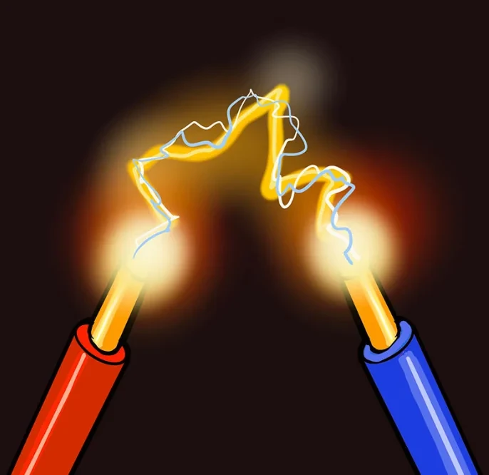
Sebuah busur dalam pemutus sirkuit adalah pelepasan listrik bercahaya—saluran plasma yang mencapai suhu 20.000°C (36.000°F)—yang terbentuk di antara kontak yang memisah ketika pemutus arus menginterupsi arus dalam kondisi berbeban. Busur ini mewakili salah satu fenomena paling keras dan intensif energi dalam teknik elektro, mampu menghancurkan kontak, memicu kebakaran, dan menyebabkan kegagalan peralatan katastrofik jika tidak dikendalikan dengan benar melalui kontak busur dan sistem pemadaman busur.
Di VIOX Electric, tim teknik kami merancang dan menguji pemutus sirkuit setiap hari, menyaksikan secara langsung bagaimana busur berperilaku di berbagai jenis pemutus—dari pemutus sirkuit miniatur (MCB) perumahan hingga pemutus sirkuit berkasur cetak (MCCB) industri dan pemutus sirkuit udara berkapasitas tinggi (ACB). Memahami pembentukan busur, peran kritis kontak busur dalam melindungi kontak utama, dan fisika yang mengatur pemadaman busur sangat penting bagi insinyur listrik, manajer fasilitas, dan siapa pun yang bertanggung jawab untuk menentukan atau memelihara peralatan proteksi sirkuit.
Panduan komprehensif ini menjelaskan fenomena busur dari perspektif manufaktur VIOX, mencakup fisika busur (titik katoda, fenomena anoda, dinamika plasma), bagaimana kontak busur mengorbankan diri untuk melindungi kontak utama, karakteristik tegangan busur, metode pemadaman di berbagai jenis pemutus, dan kriteria seleksi praktis untuk proteksi gangguan busur.
Apa itu Busur Listrik pada Pemutus Sirkuit?
Definisi Teknis Busur Listrik
Busur listrik dalam pemutus sirkuit adalah pelepasan listrik berkelanjutan melalui udara terionisasi (plasma) yang terjadi ketika kontak terpisah dalam kondisi berbeban. Berbeda dengan percikan singkat, busur adalah saluran plasma kontinu yang mandiri yang membawa arus sirkuit penuh melalui celah udara yang seharusnya bersifat isolasi.
Busur terbentuk karena arus berusaha mempertahankan jalurnya bahkan ketika gaya mekanis menarik kontak terpisah. Saat pemisahan kontak menciptakan celah udara, medan listrik intens (seringkali melebihi 3 juta volt per meter pada pemisahan awal) mengionisasi molekul udara, memecahnya menjadi elektron bebas dan ion positif. Gas terionisasi ini—plasma—menjadi konduktif secara listrik, memungkinkan arus terus mengalir melalui celah sebagai busur putih-biru yang cemerlang.
Menurut data pengujian VIOX, busur tipikal dalam MCCB 600V yang menginterupsi 10.000 ampere mencapai:
- Suhu inti: 15.000-20.000°C (lebih panas dari permukaan matahari pada 5.500°C)
- Tegangan busur: 20-60 volt (bervariasi dengan panjang busur dan besaran arus)
- Kepadatan arus: Hingga 10^6 A/cm² pada titik katoda
- Kecepatan plasma: 100-1.000 meter per detik saat digerakkan secara magnetis
- Disipasi energi: 200-600 joule per milidetik untuk gangguan arus tinggi
Konsentrasi energi ekstrem ini menjadikan pengendalian busur sebagai tantangan utama dalam rekayasa pemutus sirkuit.
Mengapa Busur Terbentuk: Fisika di Balik Pemisahan Kontak
Busur adalah konsekuensi tak terhindarkan dari membuka sirkuit pembawa arus. Proses pembentukan busur mengikuti prinsip-prinsip fisika mendasar ini:
1. Prinsip Kontinuitas Arus: Arus listrik yang mengalir melalui sirkuit induktif (yang mencakup hampir semua sistem listrik dunia nyata) tidak dapat turun ke nol secara instan. Ketika kontak mulai terpisah, arus harus menemukan jalur—busur menyediakan jalur tersebut.
2. Penyempitan Kontak dan Pemanasan Lokal: Bahkan ketika kontak tampak bersentuhan di seluruh area permukaannya, konduksi arus sebenarnya terjadi melalui titik kontak mikroskopis (asperitas) di mana ketidakteraturan permukaan bersentuhan. Kepadatan arus pada titik-titik ini sangat tinggi, menyebabkan pemanasan lokal dan pengelasan mikro.
3. Emisi Medan dan Ionisasi Awal: Saat kontak terpisah (biasanya pada 0,5-2 meter per detik dalam pemutus sirkuit), berkurangnya area kontak menyebabkan kepadatan arus melonjak. Ini memanaskan titik kontak yang tersisa hingga 2.000-4.000°C, menguapkan material kontak. Secara bersamaan, celah yang melebar menciptakan medan listrik intens yang mengionisasi uap logam dan udara di sekitarnya.
4. Pembentukan Saluran Plasma: Setelah saluran plasma konduktif terbentuk, ia menjadi mandiri melalui ionisasi termal. Arus yang mengalir melalui plasma memanaskannya lebih lanjut (pemanasan Joule: I²R), yang meningkatkan ionisasi, yang meningkatkan konduktivitas, yang mempertahankan arus. Lingkar umpan balik positif ini mempertahankan busur hingga pendinginan dan pemanjangan eksternal memadamkannya.
Dalam studi kamera kecepatan tinggi VIOX tentang busur pada pemutus sirkuit berkasur cetak, kami mengamati pembentukan busur terjadi dalam 0,1-0,5 milidetik setelah pemisahan kontak, dengan busur segera mulai bergerak di bawah gaya elektromagnetik menuju saluran busur dan ruang pemadaman.
Busur vs Percikan: Memahami Perbedaannya
Profesional listrik terkadang bingung antara busur dan percikan, tetapi keduanya adalah fenomena yang fundamentally berbeda:
| Karakteristik | Percikan | Busur |
| Durasi | Sementara (mikrodetik hingga milidetik) | Sustained (milliseconds to seconds or longer) |
| Energy | Low energy discharge | High continuous energy |
| Aliran Arus | Brief pulse, typically <1 ampere | Continuous, carries full circuit current (hundreds to thousands of amperes) |
| Suhu | Hot but brief | Extremely hot (15,000-20,000°C) |
| Self-Sustaining | No—collapses immediately | Yes—continues until external interruption |
| Potensi Kerusakan | Minimal surface erosion | Severe contact erosion, equipment damage, fire risk |
| Contoh | Static electricity discharge, switch opening light load | Circuit breaker interrupting fault current |
The distinction matters because spark suppression (such as RC snubbers across relay contacts) and kepunahan busur (as in circuit breakers) require entirely different engineering approaches.
Arcing Contacts vs Main Contacts: The Protection Mechanism
One of the most important but least understood components in modern circuit breakers is the arcing contact—a specialized contact designed to protect the breaker’s primary (main) current-carrying contacts from arc damage.
What Are Arcing Contacts?
Arcing contacts (also called arc horns or arc runners in larger breakers) are secondary electrical contacts specifically engineered to:
- Bear the arc first when contacts open under load
- Draw the arc away from main contacts through mechanical and electromagnetic means
- Withstand erosion from repeated arcing through specialized refractory materials
- Guide the arc toward extinction chambers and arc chutes
In a circuit breaker contact system, you have two distinct contact pairs:
Main Contacts (Primary Contacts):
- Large contact surface area optimized for low resistance during normal current carrying
- Materials selected for electrical conductivity and mechanical durability (typically silver-cadmium oxide, silver-tungsten, or silver-nickel alloys)
- Designed to carry rated current continuously without overheating
- Close first when breaker closes; open last when breaker opens under no-load or low-current conditions
- Expensive and difficult to replace if damaged
Arcing Contacts (Secondary Contacts):
- Smaller contact area sufficient for brief arc-carrying duty
- Materials selected for high-temperature resistance and arc erosion resistance (copper-tungsten, tungsten-carbide, or specialized arc-resistant alloys)
- Designed to withstand intense, short-duration arcing
- Open first when breaker trips under load, initiating the arc away from main contacts
- Often integrated with arc runners that physically move the arc toward extinction zones
- Considered sacrificial—designed to erode gradually and be replaced during major maintenance
How Arcing Contacts Protect the Breaker
The protection mechanism works through carefully timed sequential operation. In VIOX MCCB designs, the contact sequence follows this pattern:
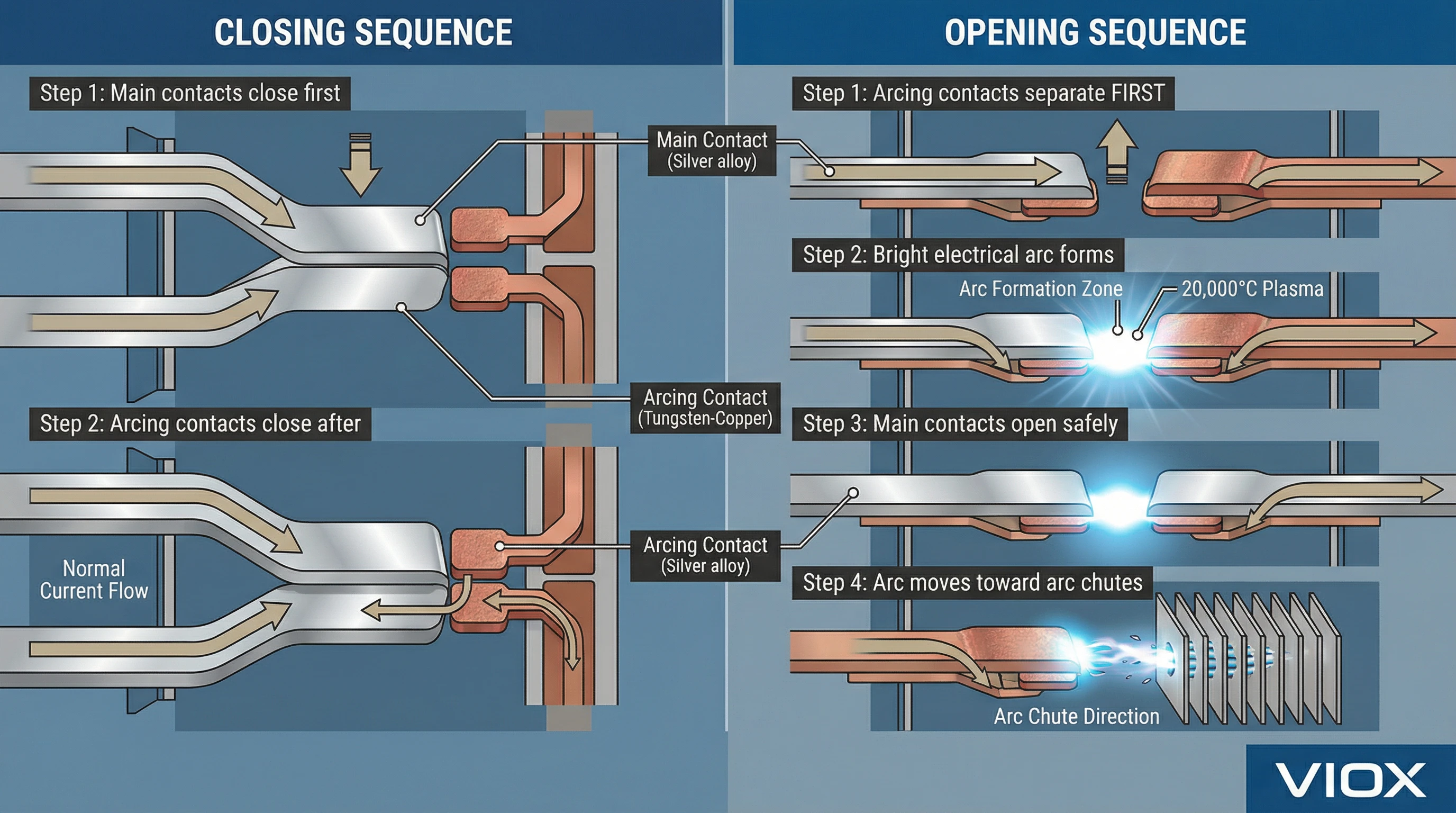
Closing Sequence (Energizing the Circuit):
- Main contacts close first, establishing the current path
- Arcing contacts close afterward (they make-last)
- During normal operation, both contact sets carry current, but main contacts carry the majority due to their lower resistance
Opening Sequence Under Load (Interrupting Current):
- Trip mechanism activates
- Arcing contacts begin to separate first (they break-first), while main contacts remain closed
- As arcing contact gap widens, an arc forms between them—but the main contacts are still closed, carrying current through the metallic path
- Main contacts open immediately after, but by this time, the arc is already established on the arcing contacts, not the main contacts
- Arcing contacts continue separating, lengthening the arc
- Electromagnetic forces (Lorentz force from arc’s own magnetic field) push the arc onto arc runners
- Arc moves into arc chutes or extinction chambers where it is cooled, lengthened, and extinguished
- Main contacts remain undamaged because they never experienced arcing
This break-first/make-last operation means main contacts only handle normal load current and open under arc-free conditions, while arcing contacts absorb all the destructive energy of arc formation and interruption.
Real-World Impact: VIOX Field Experience
In VIOX’s analysis of returned breakers that failed to interrupt faults properly, we find that roughly 60% of catastrophic failures involve either:
- Missing or severely eroded arcing contacts allowing arcs to strike main contacts directly
- Misaligned arcing contact mechanisms causing main contacts to separate before arcing contacts
- Wrong material specifications where arcing contacts used standard silver alloys instead of arc-resistant tungsten compositions
Proper arcing contact design and maintenance extends circuit breaker operational life by 3-5x in high-duty applications. In critical facilities like data centers and hospitals where our breakers protect life-safety circuits, we specify enhanced arcing contact systems with thicker tungsten layers and more frequent inspection cycles (annually instead of every 3-5 years).
The Physics of Arc Formation: Cathode Spots, Anode Phenomena, and Plasma Dynamics
To truly understand how circuit breakers control arcs, we must examine the fundamental physics governing arc behavior. This section explores arc physics at a level beyond what competitors typically cover—giving electrical engineers the deep technical knowledge to specify and troubleshoot arc-related issues.
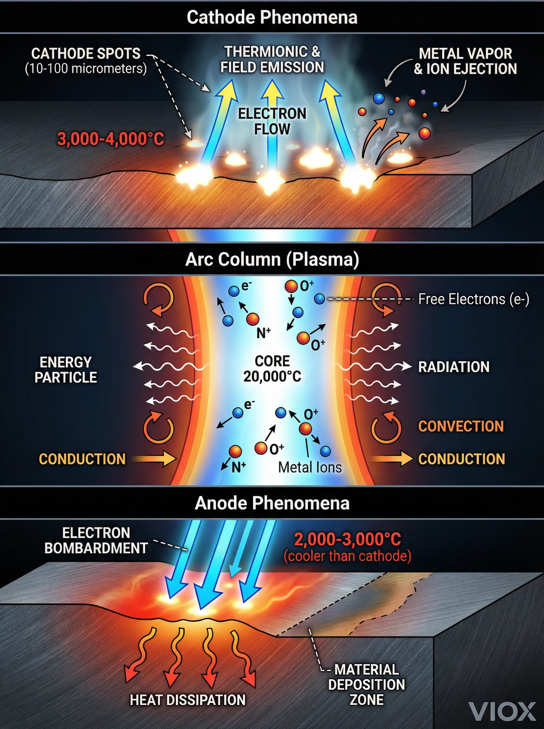
Cathode Phenomena: The Arc’s Power Source
The cathode (negative electrode) is where electrons originate in an electrical arc. Unlike steady-state conduction where current flows uniformly, arc cathodes concentrate enormous current density into tiny active regions called cathode spots.
Cathode Spot Characteristics (from VIOX laboratory measurements):
- Ukuran: 10-100 micrometers diameter
- Kepadatan arus: 10^6 to 10^9 A/cm² (million to billion amperes per square centimeter)
- Suhu: 3,000-4,000°C at the cathode surface
- Lifetime: Microseconds—spots extinguish and re-form rapidly, giving arcs their characteristic flickering appearance
- Material emission: Cathode spots vaporize electrode material, ejecting metal vapor, ions, and microdroplets into the arc column
The cathode spot operates through thermionic emission dan field emission:
- Thermionic emission: Intense heating at microscopic contact points provides thermal energy to free electrons from the metal’s surface, overcoming the work function (binding energy). For copper contacts, work function ≈ 4.5 eV, requiring temperatures >2,000 K for significant emission.
- Field emission: The intense electric field at the cathode surface (10^8 to 10^9 V/m) literally pulls electrons from the metal through quantum tunneling, even at lower temperatures. Field emission dominates in vacuum and SF6 breakers where high field strength can be maintained.
Material Selection Impact: Cathode erosion is the primary wear mechanism for arcing contacts. VIOX specifies tungsten-copper composites (typically 75% tungsten, 25% copper) for arcing contacts because:
- Tungsten’s high melting point (3,422°C) reduces vaporization rate
- Tungsten’s high work function (4.5 eV) reduces thermionic emission, stabilizing the cathode spot
- Copper provides electrical conductivity and thermal conductivity to dissipate heat
- The composite resists erosion 3-5x better than pure copper or silver contacts
Anode Phenomena: Heat Dissipation and Material Transfer
The anode (positive electrode) receives the electron flow from the cathode. Anode behavior differs fundamentally from cathode behavior:
Anode Characteristics:
- Heating mechanism: Bombardment by high-velocity electrons from the cathode, which convert kinetic energy to heat upon impact
- Suhu: Anode spots typically 500-1,000°C cooler than cathode spots
- Kepadatan arus: More diffuse than cathode—spreads over larger area
- Material transfer: In DC arcs, material erodes from cathode and deposits on anode, creating the characteristic “transferred metal” observed in arc-damaged contacts
Dalam AC circuits (the vast majority of circuit breaker applications), polarity reverses 50-60 times per second, so each contact alternates between cathode and anode. This alternating polarity explains why AC circuit breaker contacts show more uniform erosion patterns compared to DC breakers where cathode erosion dominates.
Arc Column: Plasma Physics in Action
The arc column is the luminous plasma channel connecting cathode and anode. This is where the bulk of arc energy dissipates.
Plasma Properties:
- Composition: Ionized metal vapor from electrode erosion + ionized air (nitrogen, oxygen become N+, O+ ions plus free electrons)
- Temperature profile: 15,000-20,000°C at core, decreasing radially toward edges
- Konduktivitas listrik: 10^3 to 10^4 siemens/meter—highly conductive, comparable to poor metals
- Thermal conductivity: High—plasma efficiently transfers heat to surrounding air
- Optical emission: Intense white-blue light from electronic excitation and recombination (electrons returning to ground states emit photons)
Energy Balance in the Arc Column:
The arc column must maintain thermal equilibrium between energy input (Joule heating: V_arc × I) and energy loss (radiation, convection, conduction):
- Energy Input: P_in = V_arc × I (typically 20-60V × 1,000-50,000A = 20 kW to 3 MW)
- Radiation losses: High-temperature plasma radiates UV and visible light (Stefan-Boltzmann: P ∝ T^4)
- Convection losses: Plasma rises due to buoyancy (hot gas) and is blown by magnetic forces
- Conduction losses: Heat conducted to electrodes, arc chamber walls, and surrounding gas
When energy loss exceeds energy input (such as when the arc is rapidly lengthened or cooled), plasma temperature drops, ionization decreases, resistance increases, and the arc extinguishes.
Arc Voltage Characteristics: The Key to Current Limitation
One of the most important arc parameters for circuit breaker performance is arc voltage—the voltage drop across the arc from cathode to anode.
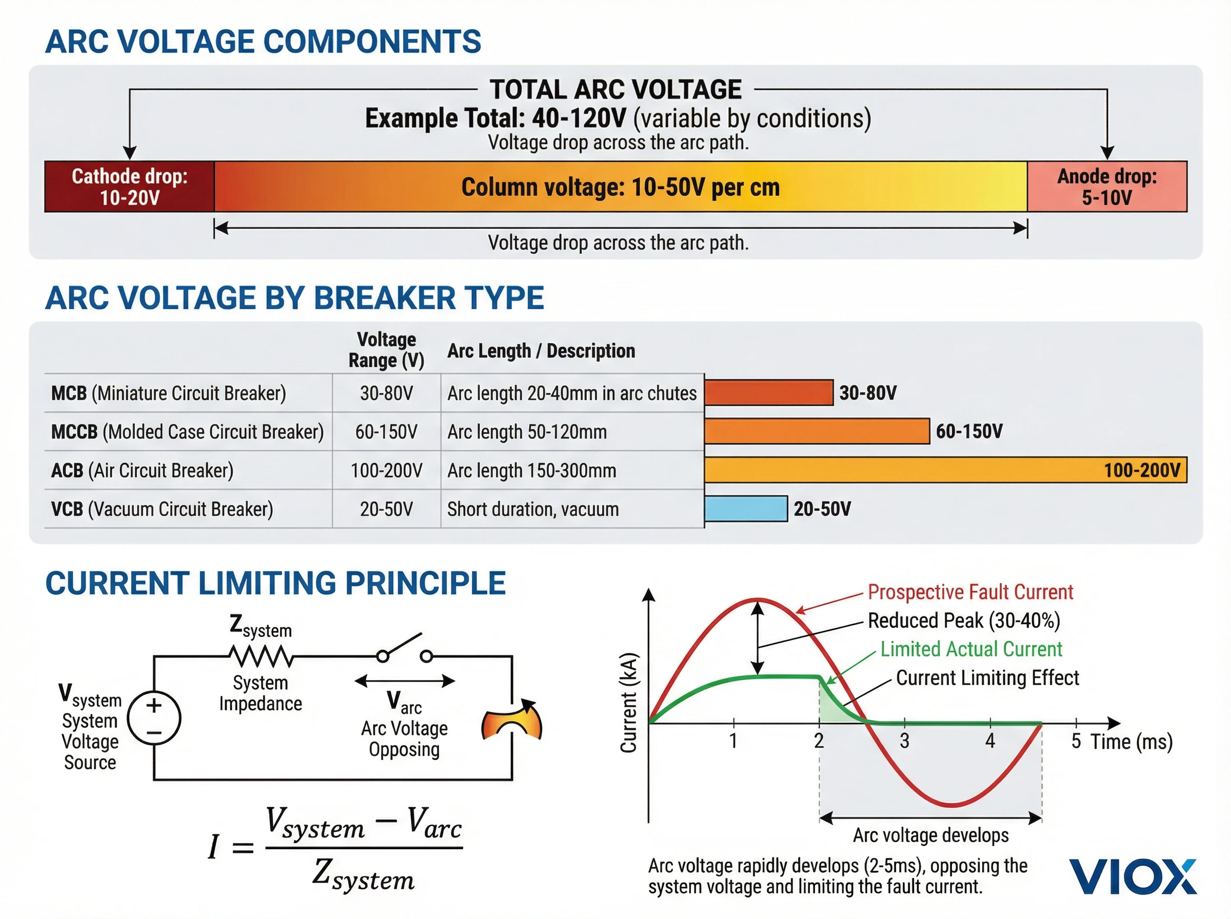
Arc Voltage Components:
V_arc = V_cathode + V_column + V_anode
Dimana:
- V_cathode: Cathode voltage drop (typically 10-20V)—energy required to extract electrons from cathode
- V_column: Column voltage drop (varies with arc length: ~10-50V per cm of arc length)
- V_anode: Anode voltage drop (typically 5-10V)—energy dissipated as electrons impact anode
Total tegangan busur in VIOX circuit breakers during fault interruption:
| Jenis Pemutus Sirkuit | Initial Arc Gap | Arc Length After Blowout | Typical Arc Voltage |
| MCB (miniature) | 2-4 mm | 20-40 mm (in arc chutes) | 30-80V |
| MCCB (molded case) | 5-10 mm | 50-120 mm (in arc chutes) | 60-150V |
| ACB (air circuit breaker) | 10-20 mm | 150-300 mm (extended arc horns) | 100-200V |
| VCB (vacuum) | 5-15 mm | No lengthening (vacuum) | 20-50V (low due to short duration) |
Arc Voltage and Current Limitation:
Arc voltage is the mechanism by which current-limiting circuit breakers reduce fault current below prospective levels. The system can be modeled as:
V_system = I × Z_system + V_arc
Rearranging:
I = (V_system – V_arc) / Z_system
By rapidly developing high arc voltage (through arc lengthening, cooling, and splitter plate interaction), the breaker reduces the net driving voltage, thereby limiting current. VIOX’s current-limiting MCCBs develop arc voltages of 120-180V within 2-3 milliseconds, reducing peak fault current to 30-40% of prospective values.
Arc Voltage Measurement: During short-circuit testing in VIOX’s 65 kA laboratory, we measure arc voltage using high-voltage differential probes and high-speed data acquisition (1 MHz sampling rate). Arc voltage waveforms show rapid rise as contacts separate, then characteristic fluctuations as the arc moves through arc chutes, then sudden collapse to zero at current zero when the arc extinguishes.
Arc Extinction Methods Across Circuit Breaker Types
Different circuit breaker technologies employ distinct arc extinction strategies, each optimized for specific voltage classes, current ratings, and application requirements.
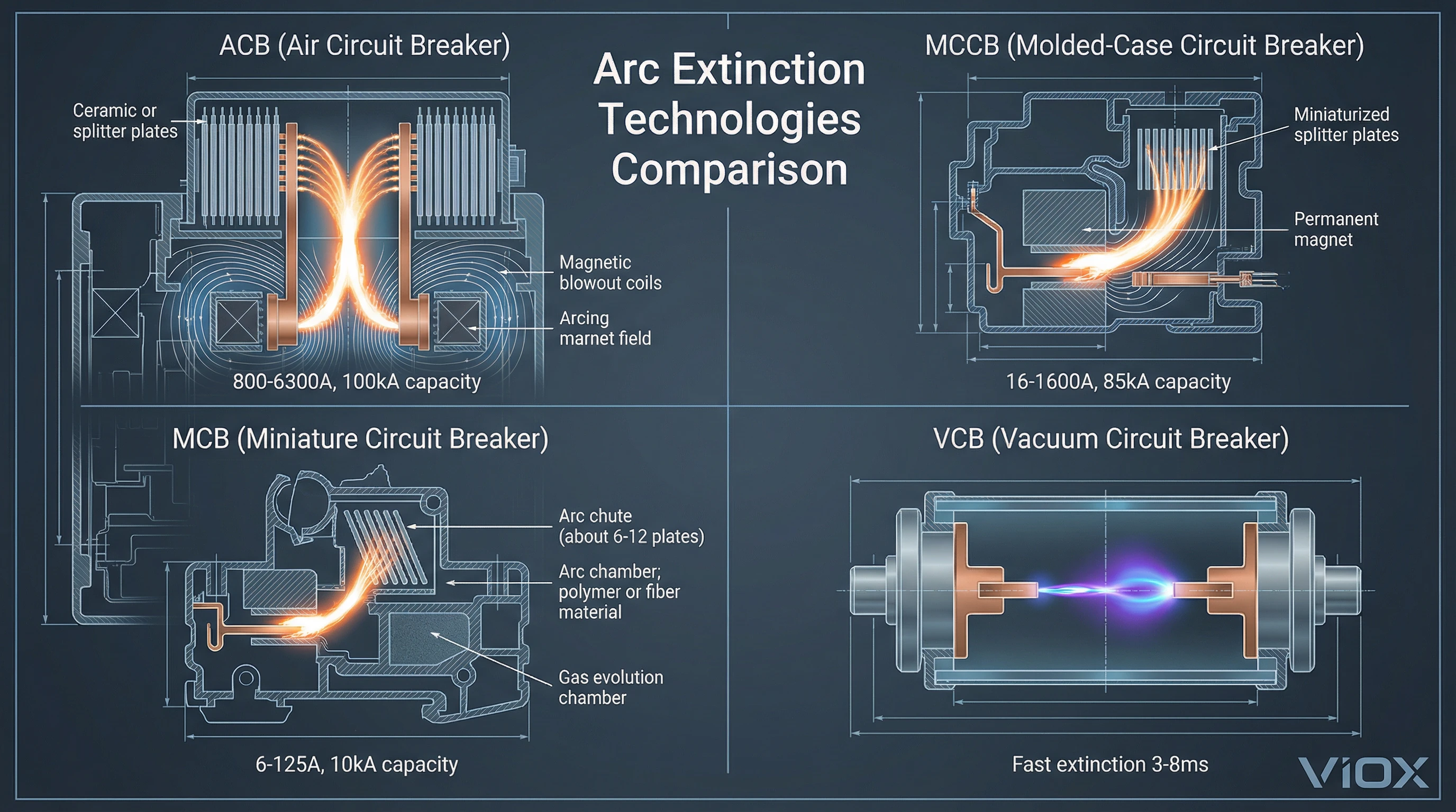
Air Circuit Breakers (ACBs): Magnetic Blowout and Arc Chutes
Pemutus sirkuit udara are the traditional workhorse for large industrial applications (800-6300A frame sizes, up to 100 kA interrupting capacity). They extinguish arcs in open air using mechanical and electromagnetic force.
Arc Extinction Mechanism:
- Ledakan Magnetik: Permanent magnets or electromagnetic coils create a magnetic field perpendicular to the arc path. The arc current interacts with this field, producing a Lorentz force: F = I × L × B
- Force direction: Perpendicular to both current and magnetic field (right-hand rule)
- Magnitude: Proportional to arc current—higher fault currents are blown faster
- Effect: Drives arc upward and away from contacts at velocities of 50-200 m/s
- Arc Runners: The arc is pushed onto extended copper or steel runners that lengthen the arc path, increasing arc voltage and resistance.
- Arc Chutes (Arc Splitters): The arc enters a chamber containing multiple parallel metal plates (typically 10-30 plates spaced 2-8mm apart). The arc is:
- Split into multiple series arcs (one between each pair of plates)
- Cooled by thermal contact with the metal plates
- Lengthened as it spreads across plate surfaces
- Each gap adds ~20-40V to arc voltage, so 20 plates = 400-800V total arc voltage
- Deionization: The combination of cooling and current zero crossing (in AC systems) allows the air to deionize, preventing arc re-strike.
VIOX ACB Design: Our VAB-series ACBs use optimized arc chute geometry with tightly spaced splitter plates (3-5mm) and high-strength permanent magnets generating 0.3-0.8 Tesla field strength. This design reliably extinguishes arcs up to 100 kA within 12-18 milliseconds.
Molded-Case Circuit Breakers (MCCBs): Compact Arc Chutes
MCCB are the most common industrial circuit breaker (16-1600A), requiring compact arc extinction systems suitable for enclosed molded cases.
Arc Extinction Strategy:
MCCBs use similar principles to ACBs but in miniaturized, optimized arc chambers:
- Arc chamber design: Integral molded arc-resistant housing (often glass-polyester composite) that contains the arc and directs gases
- Ledakan magnetik: Small permanent magnets or current-carrying blowout coils
- Compact arc chutes: 8-20 splitter plates in a confined volume
- Gas pressure venting: Controlled venting allows pressure relief while preventing external flaming
Current-Limiting MCCB: VIOX’s CLM series employs an enhanced arc chamber design:
- Tight spacing: Splitter plates spaced 2-3mm (vs. 4-6mm in standard MCCBs)
- Extended path: Arc forced to travel 80-120mm through serpentine arc chute
- Rapid voltage development: Arc voltage reaches 120-180V within 2ms
- Energi yang masuk: Reduced to 20-30% of prospective I²t
These current-limiting designs protect sensitive electronic equipment, reduce arc flash hazard, and minimize mechanical stress on bus bars and switchgear.
Miniature Circuit Breakers (MCBs): Thermal and Magnetic Arc Control
MCBs (6-125A residential/commercial breakers) use simplified arc extinction suitable for lower fault currents and compact single-pole construction.
Arc Extinction Features:
- Saluran busur: 6-12 splitter plates in a compact molded chamber
- Ledakan magnetik: Small permanent magnet or ferromagnetic arc runner
- Gas evolution: Arc heat vaporizes fiber or polymer arc chute components, generating deionizing gases (hydrogen from polymer decomposition) that help cool and extinguish the arc
VIOX MCB Design (VOB4/VOB5 series):
- Arc chutes tested to 10,000 interrupting operations per IEC 60898-1
- Arc extinguished within 8-15 ms for rated fault currents (6 kA or 10 kA)
- Internal arc containment validated to prevent external flaming
Vacuum Circuit Breakers (VCBs): Rapid Arc Extinction in Vacuum
Vacuum circuit breakers employ a radical different approach: eliminate the medium entirely. Contacts operate in a sealed vacuum bottle (10^-6 to 10^-7 Torr pressure).
Arc Extinction Mechanism:
In vacuum, there is no gas to ionize. When contacts separate:
- Metal vapor arc: Initial arc consists purely of ionized metal vapor from contact surfaces
- Rapid expansion: Metal vapor expands into vacuum and condenses on cold surfaces (shields and contacts)
- Fast deionization: At current zero, remaining ions and electrons recombine or deposit within microseconds
- High dielectric recovery: Vacuum gap regains full dielectric strength almost instantly
- Kepunahan busur: Typically within 3-8 milliseconds (1/2 to 1 cycle at 50/60 Hz)
Advantages of VCB:
- Minimal contact erosion (only metal vapor, no gas reactions)
- Very fast interruption (3-8 ms)
- Long contact life (100,000+ operations)
- No maintenance (sealed for life)
- Ukuran yang ringkas
Keterbatasan:
- More expensive than air breakers
- Voltage limited (typically 1-38 kV; not suitable for low-voltage applications)
- Potential for overvoltages (chopping currents) in some applications
VIOX manufactures VCBs (VVB-series vacuum contactors) for medium-voltage motor control and capacitor switching applications where their long life and minimal maintenance justify the cost premium.
SF6 Circuit Breakers: High-Pressure Arc Quenching
SF6 breakers use sulfur hexafluoride gas, which has exceptional arc-quenching properties:
- Kekuatan dielektrik: 2-3x air at same pressure
- Electronegativity: SF6 captures free electrons, rapidly deionizing the arc
- Thermal conductivity: Efficiently cools arc plasma
Kepunahan Busur:
Arc forms in pressurized SF6 (2-6 bar). At current zero, SF6 rapidly removes heat and captures electrons, allowing dielectric recovery within microseconds. Used primarily in high-voltage applications (>72 kV) and some medium-voltage breakers.
Pertimbangan Lingkungan: SF6 is a potent greenhouse gas (23,500× CO2 over 100 years), leading to industry transition toward vacuum and air-insulated alternatives. VIOX does not manufacture SF6 breakers, focusing instead on environmentally friendly air and vacuum technologies.
Circuit Breaker Arc Ratings and Standards
Selecting circuit breakers requires understanding standardized arc-related ratings that define the breaker’s ability to safely interrupt fault currents. These ratings vary between regions and standards organizations, but all address the same fundamental question: can this breaker safely extinguish the arc when interrupting the maximum available fault current?
Interrupting Capacity (Breaking Capacity)
Kapasitas interupsi is the maximum fault current a circuit breaker can safely interrupt without damage or failure. This rating represents the worst-case scenario: a dead short circuit (zero impedance fault) occurring at the breaker terminals.
IEC Standards (IEC 60947-2 for MCCBs):
- Icu (Ultimate Short-Circuit Breaking Capacity): The maximum fault current the breaker can interrupt once. After an Icu interruption, the breaker may require inspection or replacement. Expressed in kA (kiloamperes).
- Ics (Service Short-Circuit Breaking Capacity): The fault current the breaker can interrupt multiple times (typically 3 operations) and continue functioning normally. Usually 25%, 50%, 75%, or 100% of Icu.
UL/ANSI Standards (UL 489 for MCCBs):
- Interrupting Rating (IR or AIC): Single rating expressed in amperes (e.g., 65,000 A or “65kA”). The breaker must interrupt this current level and pass subsequent tests without failure. Generally comparable to IEC Icu.
VIOX Product Ranges:
| Jenis Pemutus Sirkuit | Typical Frame Sizes | VIOX Interrupting Capacity Range | Kepatuhan Standar |
| MCB | 6-63A | 6 kA, 10 kA | IEC 60898-1, EN 60898-1 |
| MCCB | 16-1600A | 35 kA, 50 kA, 65 kA, 85 kA | IEC 60947-2, UL 489 |
| ACB | 800-6300A | 50 kA, 65 kA, 80 kA, 100 kA | IEC 60947-2, UL 857 |
Selection Guidance: The breaker’s interrupting capacity must exceed the available fault current (also called prospective short-circuit current) at the installation point. This fault current is calculated based on utility transformer capacity, cable impedances, and source impedance. Installing a breaker with insufficient interrupting capacity results in catastrophic failure during faults—arc cannot be extinguished, breaker explodes, and fire/injury follow.
VIOX recommends safety margin: specify breakers rated at least 125% of calculated available fault current to account for utility system changes and calculation uncertainties.
Short-Time Withstand Current Ratings
Untuk selective coordination in cascaded protection systems, some breakers (especially ACBs and electronic-trip MCCBs) include short-time delay settings that intentionally withstand fault currents for brief periods (0.1-1.0 seconds) to allow downstream breakers to trip first.
Icw (IEC 60947-2): Short-time withstand current rating. The breaker can carry this fault current for a specified duration (e.g., 1 second) without tripping or damage, allowing coordination with downstream devices.
VIOX ACB models with LSI (Long-time, Short-time, Instantaneous) trip units offer adjustable short-time settings (0.1-0.4s) and Icw ratings of 30-85 kA, enabling selective coordination in industrial distribution systems.
Arc Flash Incident Energy and Labels
Beyond the breaker’s own ratings, arc flash hazard labeling requirements (per NEC 110.16, NFPA 70E, and IEEE 1584) mandate that electrical equipment display the available fault current dan waktu pembersihan to enable arc flash boundary and incident energy calculations.
VIOX ships all breakers with documentation to support arc flash labeling:
- Maximum available fault current rating
- Typical clearing times at various fault current levels (from time-current curves)
- Let-through I²t values for current-limiting breakers
Electrical contractors and engineers use this data with arc flash calculation software to determine incident energy (cal/cm²) and establish safe working distances and PPE requirements.
Pengujian dan Sertifikasi
All VIOX circuit breakers undergo third-party testing and certification to verify arc interruption performance:
Type Testing (per IEC 60947-2 and UL 489):
- Short-circuit test sequence: Breakers interrupt rated fault current multiple times (“O-t-CO” sequence: Open, time delay, Close-Open) to verify arcing contact and arc chamber durability
- Temperature rise test: Confirms arcing contacts and arc chambers don’t overheat during normal operation
- Endurance test: 4,000-10,000 mechanical operations plus rated electrical operations verify contact life
- Dielectric test: High-voltage testing confirms arc-damaged insulation maintains clearance
Routine Testing (every production unit):
- Trip current verification
- Pengukuran resistansi kontak
- Visual inspection of arcing contacts and arc chutes
- Hi-pot dielectric testing
VIOX’s quality management system (ISO 9001:2015 certified) requires batch sampling and testing per IEC 60947-2 Annex B, with full traceability from arc chamber components through final assembly.
Selecting Circuit Breakers for Arc Performance and Application
Proper circuit breaker selection considering arc behavior ensures safe, reliable interruption throughout the installation’s lifetime. Follow this systematic approach:
Step 1: Determine Available Fault Current
Calculate or measure the prospective short-circuit current at the breaker installation point. Methods:
Calculation Method:
- Obtain utility transformer kVA rating and impedance (typically 4-8%)
- Calculate transformer secondary fault current: I_fault = kVA / (√3 × V × Z%)
- Add cable impedance from transformer to breaker location
- Account for parallel sources (generators, other feeders)
Measurement Method:
Use a fault current analyzer or prospective short-circuit current tester at the installation point (requires de-energized testing or specialized live equipment).
Utility Data Method:
Request available fault current data from the electric utility for the service entrance.
For typical VIOX customer applications:
- Perumahan: 10-22 kA typical
- Bangunan komersial: 25-42 kA typical
- Fasilitas industri: 35-100 kA (up to 200 kA near large transformers)
Step 2: Select Interrupting Capacity with Safety Margin
Choose breaker Icu/AIC rating ≥ 1.25 × available fault current.
Example: Available fault current = 38 kA → specify breaker rated ≥ 48 kA → VIOX VPM1 series MCCB rated 50 kA is appropriate.
Step 3: Evaluate Arc Energy and Current Limitation
For sensitive equipment protection (electronics, variable frequency drives, control systems), consider current-limiting breakers that reduce let-through energy:
Current-Limiting Performance: VIOX CLM series MCCBs with current-limiting arc chutes achieve:
- Peak let-through current: 30-45% of prospective fault current
- I²t let-through: 15-25% of prospective I²t energy
- Limiting occurs within first 2-5 ms (less than 1/4 cycle at 60 Hz)
This dramatic energy reduction protects downstream cables, bus bars, and equipment from thermal and mechanical stress.
Step 4: Consider Arc Flash Safety and Accessibility
In locations where workers must access energized equipment:
- Specify breakers with arc-resistant enclosures or remote racking mechanisms
- Use electronic trip units with zone-selective interlocking (ZSI) for faster fault clearing
- Consider arc flash relays with optical detection for ultra-fast tripping (2-5 ms)
- Install arc flash warning labels and establish safety procedures per NFPA 70E
VIOX ACB models with draw-out mechanisms allow breaker removal while maintaining arc chamber alignment and safety—critical for maintenance in high-energy systems.
Step 5: Specify Arcing Contact Material and Maintenance Intervals
For high-duty applications (frequent switching, high fault current environments):
Enhanced arcing contacts: Specify tungsten-copper composition with increased mass
Inspection intervals: VIOX recommendations based on application:
| Duty Cycle | Inspections per Year | Arcing Contact Expected Life |
| Light (residential, commercial offices) | 0 (visual only) | 20-30 years |
| Medium (retail, light industrial) | Setiap 3-5 tahun | 10-20 tahun |
| Heavy (manufacturing, repetitive starting) | Setiap tahun | 5-10 tahun |
| Severe (primary switchgear, high fault exposure) | Every 6 months | 2-5 years or after major fault |
Step 6: Verify Coordination and Selectivity
Plot time-current curves to ensure proper arc-fault coordination:
- Upstream breaker should not trip before downstream breaker during faults
- Adequate time margin (typically 0.2-0.4 seconds) between curves
- Account for breaker arc time and current-limiting effects
VIOX provides TCC (time-current curve) data and coordination software to facilitate selectivity analysis.
Arc-Related Maintenance, Inspection, and Troubleshooting
Proper maintenance extends arcing contact life, maintains interrupting capability, and prevents arc-related failures.
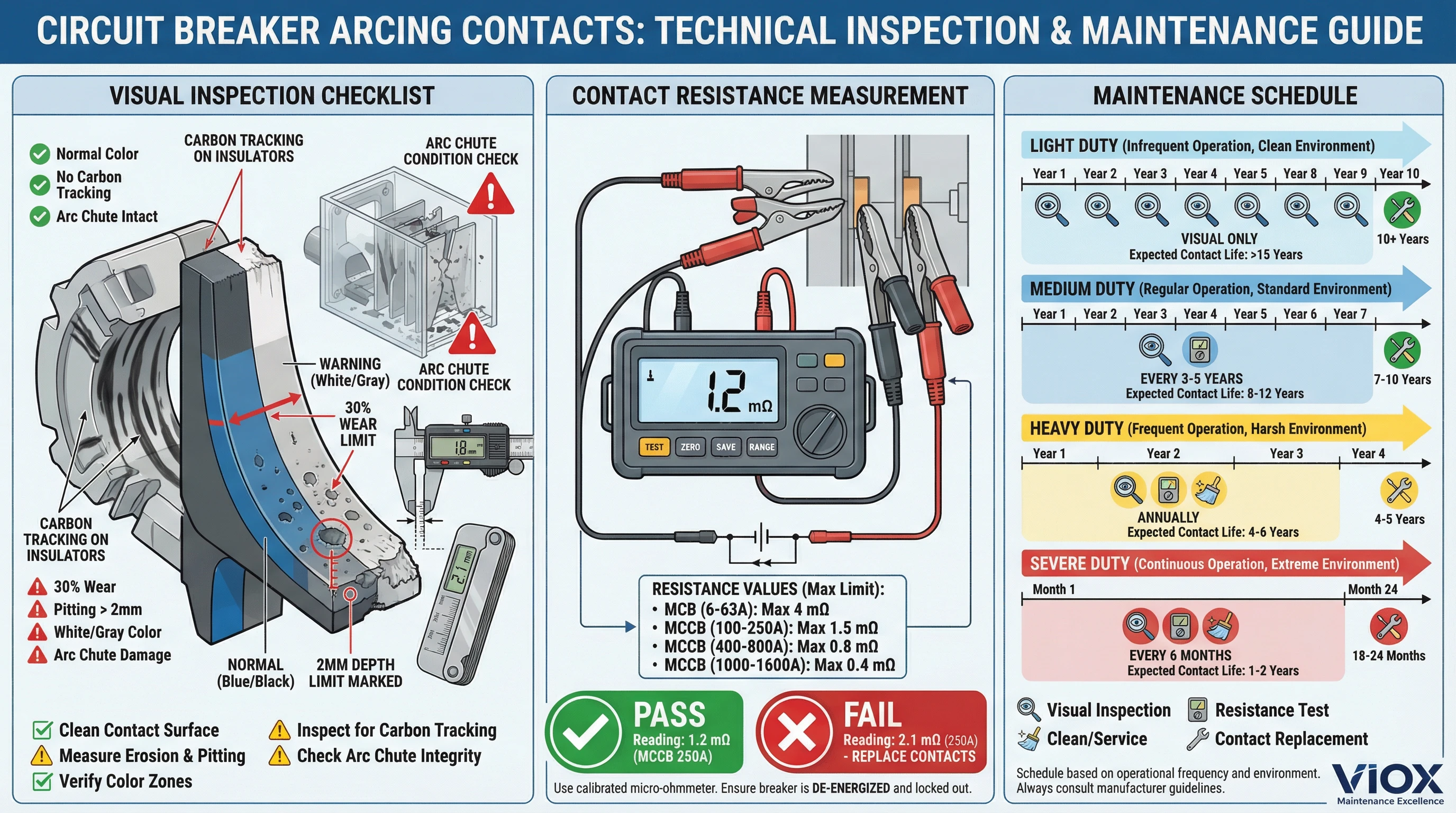
Visual Inspection of Arcing Contacts
Perform visual inspection during scheduled maintenance (breaker de-energized and withdrawn):
What to look for:
- Contact erosion: Material loss from arcing contact tips—acceptable if <30% original material remains
- Pitting and cratering: Deep craters indicate severe arcing; replace if crater depth >2mm
- Perubahan warna: Blue/black oxidation is normal; white/gray deposits suggest overheating
- Carbon tracking: Conductive carbon paths on insulators from arc plasma—clean or replace affected parts
- Warping or melting: Indicates excessive arc energy or failed arc extinction—replace breaker
- Arc chute damage: Broken splitter plates, melted barriers, or soot accumulation—clean or replace arc chamber
VIOX inspection tools: Contact thickness gauges and wear limit templates available for all MCCB/ACB models to quantify erosion.
Contact Resistance Measurement
Measure resistance across each pole using micro-ohmmeter (digital low-resistance ohm meter):
Acceptable values (VIOX breakers, per IEC 60947-2):
| Breaker Frame Size | New Contact Resistance | Maximum Allowable |
| MCB (6-63A) | 0.5-2 mΩ | 4 mΩ |
| MCCB (100-250A) | 0.1-0.5 mΩ | 1.5 mΩ |
| MCCB (400-800A) | 0.05-0.2 mΩ | 0.8 mΩ |
| MCCB (1000-1600A) | 0.02-0.1 mΩ | 0.4 mΩ |
| ACB (1600-3200A) | 0.01-0.05 mΩ | 0.2 mΩ |
Rising contact resistance indicates:
- Arcing contact erosion
- Main contact contamination or oxidation
- Reduced contact pressure (worn springs)
- Misalignment
If resistance exceeds maximum allowable, replace arcing contacts or entire breaker depending on model and repairability.
Troubleshooting Arc-Related Problems
Problem: Breaker trips immediately when closing onto load
- Kemungkinan Penyebabnya: Downstream short circuit (verify with megohmmeter testing), Instantaneous trip setting too low, Worn arcing contacts causing high initial resistance and inrush current
- Solusi: Isolate downstream load, test circuit continuity, inspect arcing contacts
Problem: Visible arcing during normal operation
- Kemungkinan Penyebabnya: Main contacts not closing properly (arcing contacts carrying continuous current), Loose connections at breaker terminals, Contact contamination reducing conductivity, Mechanical misalignment
- Solusi: Immediately de-energize and inspect. Arcing during normal operation indicates imminent failure—replace breaker.
Problem: Breaker fails to interrupt fault
- Kemungkinan Penyebabnya: Fault current exceeds interrupting rating (arc cannot be extinguished), Severe arcing contact erosion, Arc chamber damage or blockage, Contamination in arc chute (metal particles shorting splitter plates)
- Solusi: Replace breaker immediately. Failure to interrupt indicates critical safety hazard.
Problem: Burning smell or smoke from breaker during fault interruption
- Kemungkinan Penyebabnya: Normal arc by-products (ozone, NOx) if occurs once during fault clearing, Organic insulation pyrolysis if arc energy excessive, Internal component overheating
- Solusi: If single event during fault clearing, perform post-interruption inspection per IEC 60947-2 (visual, resistance, dielectric). If repeated or during normal operation, replace breaker.
When to Replace Breakers After Arc Exposure
VIOX recommends breaker replacement under these conditions:
- Interruption of ≥80% of rated Icu: Single interruption near capacity causes severe arcing contact erosion
- Multiple interruptions ≥50% Icu: Cumulative damage exceeds design life
- Visible contact erosion >30%: Insufficient material remaining for reliable future interruption
- Contact resistance exceeds maximum: Indicates degraded current path
- Arc chamber damage: Broken splitter plates, melted components
- Age >20 years in service: Even without faults, material aging affects arc extinction
Most VIOX commercial/industrial customers implement 25-year replacement cycles for critical MCCBs regardless of visible condition, ensuring reliable arc interruption when needed.
Frequently Asked Questions: Arcs in Circuit Breakers
Apa yang membuat busur listrik pada pemutus sirkuit begitu berbahaya?
Arcs in circuit breakers are dangerous because they reach temperatures of 20,000°C—hotter than the sun’s surface—creating extreme fire, explosion, and electrocution hazards. The arc plasma can instantly ignite nearby combustible materials, vaporize metal components, and generate pressure waves exceeding 10 bar (145 psi) that rupture enclosures. Arc flash incidents cause severe burns, permanent blindness from intense UV light, and hearing damage from explosive sound (140+ dB). Additionally, arcs produce toxic gases including ozone, nitrogen oxides, and carbon monoxide. Without proper arcing contacts and arc extinction systems, uncontrolled arcs can propagate through electrical systems, causing cascading failures and facility-wide damage.
Berapa lama busur listrik bertahan dalam pemutus sirkuit selama pemutusan gangguan?
Modern circuit breakers extinguish arcs within 8-20 milliseconds in AC systems (typically by the first or second current zero crossing). VIOX MCCBs with optimized arc chutes achieve interruption in 10-16 ms at rated fault current. Vacuum circuit breakers are faster (3-8 ms) due to rapid arc extinction in vacuum. However, if the breaker’s interrupting capacity is exceeded or arc chambers are damaged, arcs can persist for hundreds of milliseconds or longer, releasing massive energy and causing catastrophic failure. The arc duration directly correlates with energy release: E = V × I × t, so faster extinction significantly reduces damage and hazard.
Apa perbedaan antara kontak busur dan kontak utama dalam pemutus sirkuit?
Arcing contacts and main contacts serve distinct roles in circuit breakers. Main contacts are large-area, low-resistance contacts optimized to carry rated current continuously with minimal heating. They use expensive materials (silver alloys) for conductivity and durability. Arcing contacts are smaller, secondary contacts made from arc-resistant materials (tungsten-copper) designed to handle the destructive arc during interruption. The critical difference is timing: arcing contacts open first (break-first) when the breaker trips, drawing the arc away from main contacts. This break-first/make-last operation protects main contacts from arc damage, extending breaker life by 3-5× compared to single-contact designs. VIOX testing shows that 60% of premature breaker failures result from missing or eroded arcing contacts allowing arcs to damage main contacts.
Dapatkah Anda melihat busur yang terbentuk di dalam pemutus sirkuit?
You should never intentionally observe arc formation as the intense UV and visible light (comparable to welding arc brightness) can cause permanent retinal damage within milliseconds—a condition called “arc eye” or photokeratitis. During normal operation, circuit breakers are enclosed and arcs occur inside arc chambers, invisible to operators. VIOX uses high-speed cameras with proper filtering in our 65 kA test laboratory to study arc behavior safely. In the field, if you see arcs or flashing light from a breaker during normal operation (not during fault clearing), immediately de-energize the equipment—visible arcing indicates imminent catastrophic failure. During fault clearing, brief internal flashing visible through indicator windows is normal for high-current interruptions.
Bagaimana tegangan busur mempengaruhi pembatasan arus pada pemutus sirkuit?
Arc voltage is the key mechanism enabling current-limiting circuit breakers to reduce fault current below prospective levels. As the arc lengthens through magnetic blowout and travels through arc chutes, arc voltage rises rapidly (typically 80-200V in VIOX MCCB arc chambers). This voltage opposes the system voltage, reducing net voltage available to drive fault current: I_actual = (V_system – V_arc) / Z_system. By rapidly developing high arc voltage within 2-5 milliseconds, current-limiting breakers achieve peak let-through currents only 30-40% of prospective fault levels. VIOX CLM series MCCBs use tight-spaced splitter plates (2mm) and extended arc chute paths (80-120mm) to maximize arc voltage, protecting downstream equipment from thermal (I²t) and mechanical (I_peak²) stress during faults.
Apa yang menyebabkan busur pemutus arus menjadi lebih parah?
Arc severity increases with multiple factors: higher fault current (more energy input), longer arc duration (delayed extinction), inadequate interrupting capacity (breaker undersized for available fault current), contaminated or eroded arcing contacts (irregular arc formation), worn components (reduced contact pressure, damaged arc chutes), improper installation (loose terminals causing external arcing), and environmental conditions (high humidity reduces dielectric strength, altitude reduces air density affecting arc cooling). In VIOX’s analysis of severe arc incidents, the most common cause is installing breakers with insufficient interrupting capacity for the available fault current—when prospective fault exceeds the breaker’s Icu rating, the arc cannot be extinguished and catastrophic failure follows. Always verify available fault current and specify breakers rated ≥125% above that value.
Bagaimana pemutus AFCI berbeda dari pemutus sirkuit standar dalam mendeteksi busur listrik?
Pemutus Sirkuit Gangguan Busur (AFCIs) mendeteksi busur paralel berbahaya (busur dari saluran ke netral atau saluran ke tanah akibat kabel yang rusak, sambungan longgar, atau kabel yang aus) yang tidak dapat dideteksi oleh pemutus standar karena busur ini menarik arus yang tidak cukup untuk memicu proteksi arus lebih. AFCIs menggunakan elektronik canggih untuk menganalisis bentuk gelombang arus guna mengidentifikasi tanda karakteristik frekuensi tinggi (biasanya 20-100 kHz) yang dihasilkan oleh busur—pola tidak teratur dan kacau yang berbeda dari arus beban normal. Ketika AFCI mendeteksi tanda busur yang melebihi tingkat dan durasi ambang batas, ia akan trip untuk mencegah kebakaran listrik. Pemutus sirkuit standar hanya mendeteksi busur seri (busur pada jalur arus yang disengaja selama gangguan) saat mereka trip untuk membersihkan kesalahan; mereka tidak dapat mendeteksi busur paralel pada kabel cabang. Pemutus industri/komersial VIOX berfokus pada interupsi busur seri berenergi tinggi, sementara pemutus AFCI perumahan (di luar jangkauan produk kami) khusus mendeteksi busur paralel berenergi rendah yang menyebabkan kebakaran.
Apa yang terjadi jika pemutus sirkuit tidak dapat memadamkan busur listrik?
If a circuit breaker fails to extinguish an arc, catastrophic failure follows within seconds. The sustained arc continues drawing fault current (potentially tens of thousands of amperes), releasing massive energy (megajoules per second) that: 1) Vaporizes and melts breaker internal components, creating conductive metal vapor that propagates the arc throughout the enclosure; 2) Generates extreme pressure (20+ bar) that ruptures the breaker case, projecting molten metal and plasma externally; 3) Ignites surrounding materials—cables, enclosures, building structures—causing electrical fire; 4) Creates phase-to-phase or phase-to-ground arcs in upstream equipment, cascading the failure; and 5) Poses extreme arc flash hazard to nearby personnel with incident energies exceeding 100 cal/cm². This is why specifying proper interrupting capacity is critical. VIOX’s rigorous testing per IEC 60947-2 verifies every breaker model reliably extinguishes arcs up to rated Icu under worst-case conditions.
Kesimpulan
Arcs are a destructive force, but with precision-engineered arcing contacts and arc extinction systems, they can be controlled. Understanding the physics of arcing—from cathode spots to plasma dynamics—allows engineers to select the right protection equipment and maintain it for safety and reliability. VIOX Electric continues to advance arc control technology, ensuring our breakers deliver superior protection for your critical electrical infrastructure.
