NPN 4-wire proximity switches are versatile sensors used in industrial automation for detecting objects without physical contact, featuring dual-channel outputs that provide both Normally Open (NO) and Normally Closed (NC) signals simultaneously, enhancing their flexibility and diagnostic capabilities in control systems.
Definition and Functionality
These specialized sensors utilize four wires for operation: two for power supply (positive voltage and ground) and two for output signals (Normally Open and Normally Closed). The dual-channel output configuration allows for simultaneous transmission of both NO and NC signals, enhancing the sensor’s flexibility in control systems. This complementary output design aids in diagnostics by indicating potential malfunctions if both outputs fail to operate as expected. The separation of power and signal lines in 4-wire sensors minimizes interference and ensures stable operation, making them particularly suitable for environments with fluctuating power conditions.
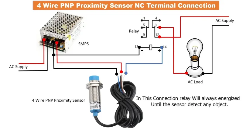
4 Wire Proximity Sensor Wiring Diagram
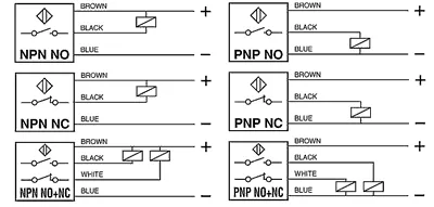
The wiring configuration of NPN 4-wire proximity switches is crucial for their proper operation and integration into control systems. These sensors typically feature four distinct wires, each with a specific function and color-coding:
- Brown: This wire connects to the positive voltage supply (VCC), usually 12-24V DC.
- Blue: Serves as the ground or negative connection (GND).
- Black: Represents the Normally Open (NO) output.
- White: Functions as the Normally Closed (NC) output.
The power supply wires (brown and blue) provide the necessary voltage for the sensor’s operation, while the black and white wires transmit the output signals. This separation of power and signal lines contributes to the sensor’s stability and noise immunity.
When wiring these sensors into a control system, it’s essential to connect the load devices appropriately:
- For the NO output (black wire), the load is typically connected between this wire and the negative supply (blue wire). When an object is detected, current flows through this circuit, activating the connected device.
- For the NC output (white wire), the load is similarly connected between this wire and the negative supply. In this case, current flows when no object is detected, and the circuit opens upon object detection.
It’s important to note that these sensors often include internal pull-up resistors on both output lines, which maintain a stable logic level even when no external load is connected. This feature prevents floating inputs and ensures reliable signal transmission.
For enhanced functionality and diagnostics, some control systems may utilize both NO and NC outputs simultaneously. This configuration allows for cross-checking of sensor states and can help identify potential sensor failures or wiring issues.
When installing NPN 4-wire proximity sensors, it’s crucial to adhere to the manufacturer’s specifications regarding maximum load current and voltage ratings to prevent damage to the sensor or connected equipment. Additionally, proper shielding and grounding practices should be employed, especially in environments with high electromagnetic interference, to maintain signal integrity and sensor performance.
Advantages and Applications
The dual-channel output capability of NPN 4-wire proximity switches offers significant advantages in industrial automation. These sensors excel in metal detection, position sensing, limit control, and quality assurance processes. Their versatility extends to detecting both metallic and non-metallic objects, including liquids, plastics, bulk solids, and powders. This flexibility, combined with their enhanced signal stability, makes them invaluable in modern manufacturing and production lines where precise object detection is crucial for efficient operations.
Output Operation
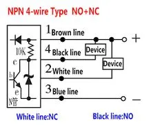
The NPN 4-wire proximity switch operates based on the principle of an internal NPN transistor network connected to both output pins (black NO and white NC). When no object is detected, the NO (Normally Open) output transistor remains non-conducting, while the NC (Normally Closed) output transistor conducts.
In the absence of an object:
- The black NO wire registers approximately 12V (VCC) when measured against the blue ground wire due to an internal pull-up resistor.
- The white NC wire shows approximately 0V when measured against the blue ground wire, as the internal transistor conducts and pulls the logic level to ground.
When an object is detected, the states reverse:
- The black NO wire transitions to approximately 0V as the transistor begins to conduct.
- The white NC wire switches to approximately 12V as its transistor stops conducting.
This complementary output behavior ensures that at least one output is always in a known state, enhancing reliability and fault detection capabilities. The internal pull-up resistors prevent floating inputs, maintaining a stable logic level even when no external load is connected.
It’s important to note that during initial power-up or in certain sensing conditions, there might be a brief pulse or transition period where both outputs momentarily show high voltage before settling into their proper states. This characteristic can be useful for diagnostics but may require consideration in time-sensitive applications.
The dual-output nature of these sensors allows for versatile integration into control systems. For instance, the NO output can be used to trigger an action when an object is present, while the NC output can simultaneously confirm the absence of objects or serve as a failsafe mechanism.
