
A control panel builder once ordered 50 time delay relays based on a single specification: “10-second delay, 24V.” When the relays arrived, half wouldn’t trigger reliably because the control signal was only 20 milliseconds—below the 50 ms minimum input pulse width buried in the datasheet. The project stalled for two weeks while replacement relays shipped. The builder knew what timing function he needed but missed a critical specification that determined whether the relay would actually work.
This scenario repeats across industries. Engineers specify relays, procurement managers compare quotes, maintenance technicians cross-reference replacements—all relying on datasheets to make the right call. But time relay datasheets pack dozens of specifications into dense tables, many using terminology that varies across manufacturers. Miss the wrong spec, and you get field failures, premature contact wear, or relays that work in the lab but fail under real-world temperature and voltage swings.
Learning to read datasheets isn’t about memorizing every specification—it’s about knowing which specs matter for your application and how to interpret them correctly. Timing accuracy means something different at full scale versus short ranges. Contact ratings for resistive loads don’t apply to inductive solenoids. Operating voltage range isn’t the same as release voltage. These distinctions transform a datasheet from an intimidating spec sheet into a decision tool that prevents costly mistakes and ensures reliable operation.
Datasheet Structure: What You’ll Find and Where
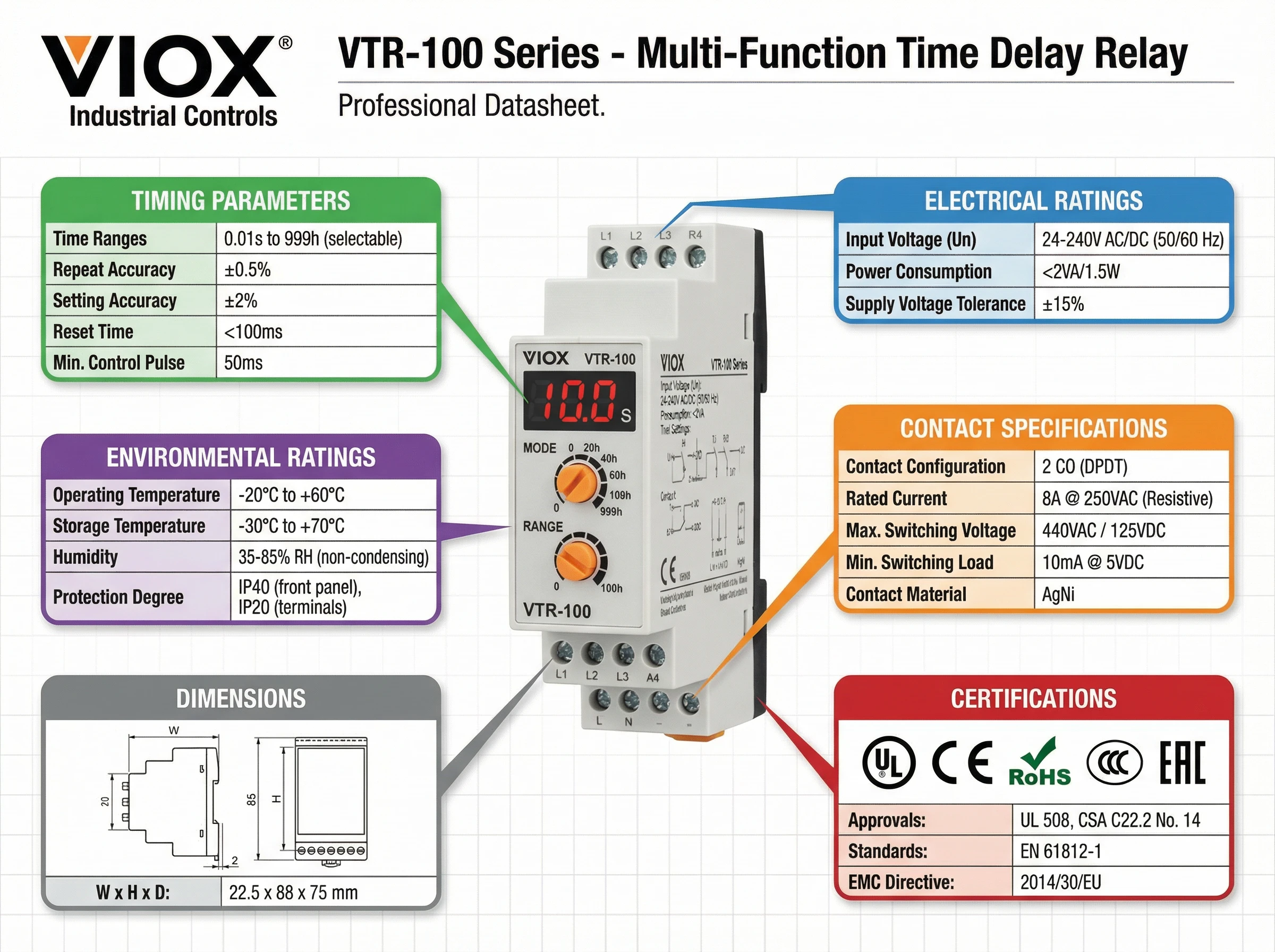
Time relay datasheets follow a predictable structure, though manufacturers arrange sections differently. Knowing where to find information quickly saves time and reduces the chance of overlooking critical specs.
Most datasheets open with a model overview and operation modes section showing the available timing functions—on-delay, off-delay, interval, multifunction. This tells you which relay variants exist within a product family. Next comes time range settings: the available time scales (0.1 s, 1 s, 10 s, up to 100 hours) and how you adjust timing—potentiometer dial, digital display, or programmable parameters.
Electrical ratings occupy the core of most datasheets. You’ll find tables covering supply voltage specifications (rated voltage, allowable range, frequency), input circuit specifications (threshold levels, minimum pulse width), and power consumption. These determine whether the relay will energize reliably in your control circuit.
Output specifications detail contact configuration (SPDT, DPDT), contact ratings by load type (resistive, inductive AC/DC, lamp loads), and endurance (mechanical life, electrical life at rated load). This section tells you whether the relay can actually switch your load without premature failure.
Performance characteristics quantify timing behavior: accuracy of operating time (usually as percent of full scale), setting error from the adjustment mechanism, influence of supply voltage variation, and influence of ambient temperature. You’ll also find recovery time (minimum time between operations) and minimum control impulse duration here.
Environmental ratings cover operating and storage temperature ranges, humidity limits, vibration/shock resistance, and pollution degree per IEC 60664-1. These specs determine whether the relay survives your installation environment.
Standards and approvals list certifications: IEC/EN 61812-1 (the international time relay standard), UL 508/cUL (North America), CE marking with referenced EMC directives. This section proves compliance and often includes insulation coordination data—overvoltage category and impulse withstand voltage.
Dimensions and wiring show physical size, mounting method (DIN-rail width, plug-in socket pinout, panel cutout), terminal types, and connection diagrams. For replacement scenarios, this section determines drop-in compatibility.
Understanding this structure lets you navigate any manufacturer’s datasheet efficiently—you know what information exists and where to find it.
Timing Specifications Explained
Timing specifications define how accurately and consistently the relay delivers its intended delay. These specs directly determine whether your application gets the timing precision it needs—or experiences frustrating variability that causes process problems.
Time Ranges and Setting Scales
Datasheets list available time ranges as base scales: 0.1 s, 1 s, 10 s, 100 s, up to 100 hours or more. Each scale covers a settable range, typically 1.2× the base value. For example, a 10 s scale might cover 10–120 seconds. This structure tells you two things: whether your target delay falls within the relay’s capability, and how fine-grained the adjustment will be. A 0.1 s scale gives you precise sub-second control; a 100 s scale trades precision for long-duration capability.
Accuracy of Operating Time
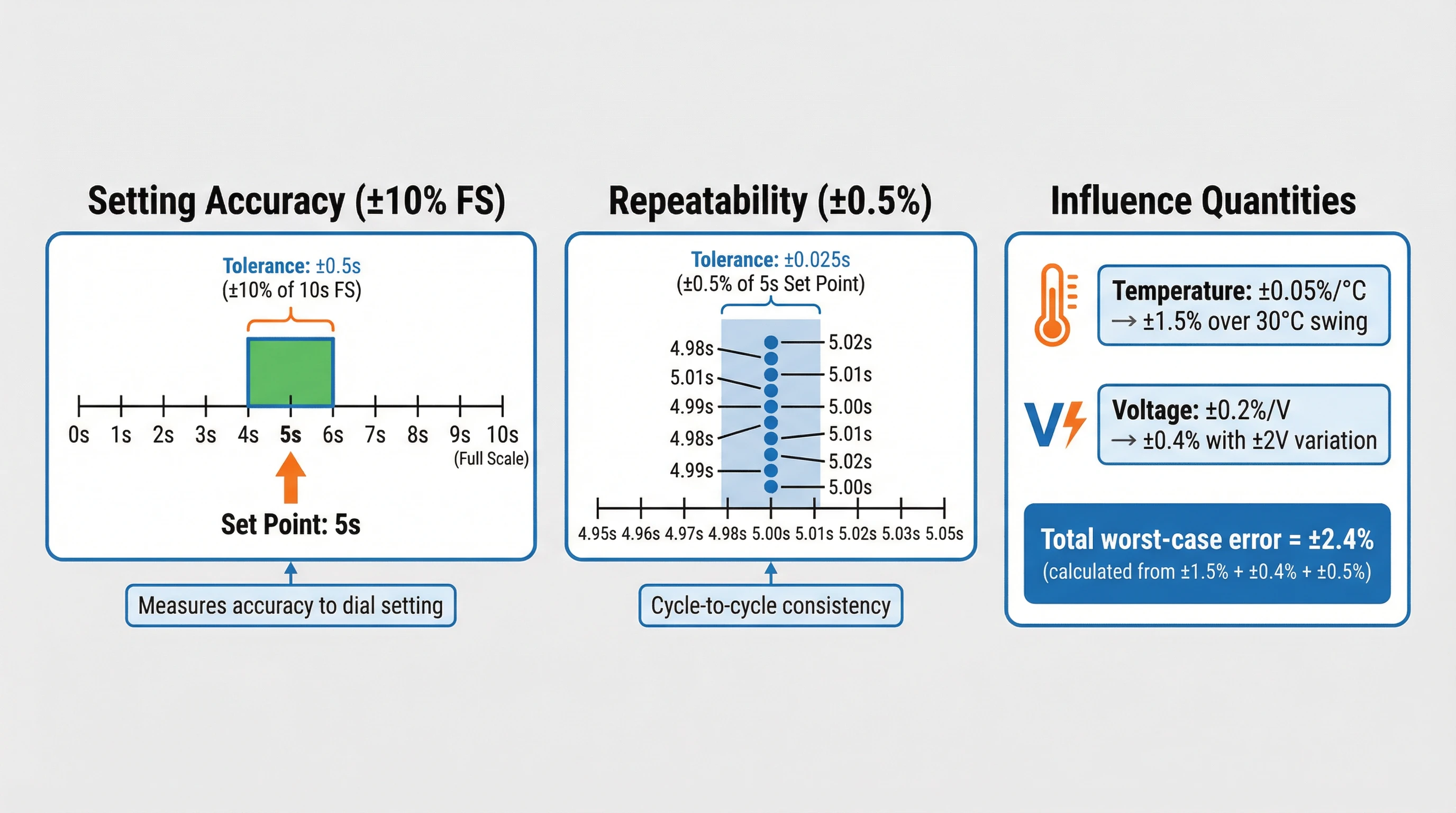
This is the deviation between the set timing value and the actual measured timing under reference conditions (usually 23°C, rated voltage). Accuracy is almost always expressed as percent of full scale (FS), not percent of set value. This distinction matters enormously.
Example: A relay with ±1% FS accuracy on a 12-second scale has a ±0.12 second error band—whether you set 2 seconds or 12 seconds. At a 2-second setting, that ±0.12 s represents a ±6% error relative to your target. At 12 seconds, it’s only ±1%. The shorter your timing setting relative to full scale, the larger the percentage error becomes. For very short ranges (sub-second), datasheets often add an absolute term: “±1% FS + 10 ms max.” This accounts for circuit switching delays that don’t scale with time range.
When comparing relays, always check whether accuracy is specified at full scale or as a range-dependent value. Some manufacturers list different accuracy figures for different time scales.
Setting Error vs Operating Time Accuracy
Setting error quantifies how precisely you can dial in your target time using the relay’s adjustment mechanism—potentiometer, rotary switch, or digital interface. A typical spec might read “±10% FS.” This is separate from operating time accuracy, which measures how closely the relay hits the target you’ve set. Total timing uncertainty is the combination of both: you might set the wrong target (setting error) and then miss that target by the operating time accuracy.
For critical timing applications, minimize setting error by using digital/programmable relays with numeric entry rather than analog potentiometer dials.
Herhaalbaarheid
Repeatability (sometimes called “repeat accuracy”) measures how consistently the relay produces the same timing value across multiple operations under identical conditions. High-quality relays show repeatability within ±0.5% FS; lower-cost units may drift to ±2% FS or more. In applications where cycle-to-cycle consistency matters—sequential machine operations, synchronized motor starting—repeatability becomes your critical spec.
Some datasheets roll repeatability into the overall accuracy specification. Others list it separately. If you see only “accuracy of operating time” with no repeatability callout, assume repeatability is included within that accuracy band.
Influence Quantities: Voltage and Temperature
Timing accuracy degrades under non-ideal conditions. Datasheets quantify this as “influence of supply voltage” and “influence of ambient temperature,” again expressed as percent of full scale.
Typical voltage influence: ±0.5% FS over the allowable supply voltage range (e.g., 85%–110% of rated voltage). If your supply voltage swings from 22 VDC to 26 VDC on a 24 VDC relay, expect up to ±0.5% FS additional timing error.
Typical temperature influence: ±2% FS over the operating temperature range (e.g., −20°C to +60°C). Installing a relay in a hot control cabinet near heating equipment can push ambient temperature to 50°C or higher, adding significant timing drift.
Critical tolerance stacking: Your worst-case timing error is the sum of operating time accuracy + voltage influence + temperature influence, all on a full-scale basis. For a 10 s scale relay with ±1% FS accuracy, ±0.5% FS voltage influence, and ±2% FS temperature influence, your worst-case band is ±3.5% FS = ±0.35 seconds. If you need tighter timing than that, choose a relay with better influence specifications or control your voltage and temperature environment more tightly.
Recovery Time and Minimum Control Impulse
Recovery time (also called “minimum power-OFF time” or “reset time”) specifies how long the relay must remain de-energized before it can reliably reset and start a new timing cycle. Typical values range from 0.05 s to 0.1 s. Cycling the relay faster than this can leave timing capacitors partially charged or internal logic in an undefined state, producing incorrect timing on the next cycle.
Minimum control impulse (or “minimum input signal width”) defines the shortest pulse duration that reliably triggers timing on relays with separate start inputs. A spec of 50 ms means your control signal must stay high for at least 50 milliseconds. Shorter pulses may be ignored or produce erratic behavior. This is the spec that tripped up the control panel builder in our opening example—20 ms pulses couldn’t trigger a relay requiring 50 ms minimum.
Always verify your control circuit’s pulse width and cycle timing against these specifications during design. Don’t assume “fast” control signals will work without checking.
Electrical Ratings: Voltage and Power Requirements
Electrical ratings define the relay’s input circuit specifications—what it needs to operate reliably. Get these wrong, and the relay won’t energize consistently or may reset unexpectedly.
Rated Supply Voltage and Operating Range
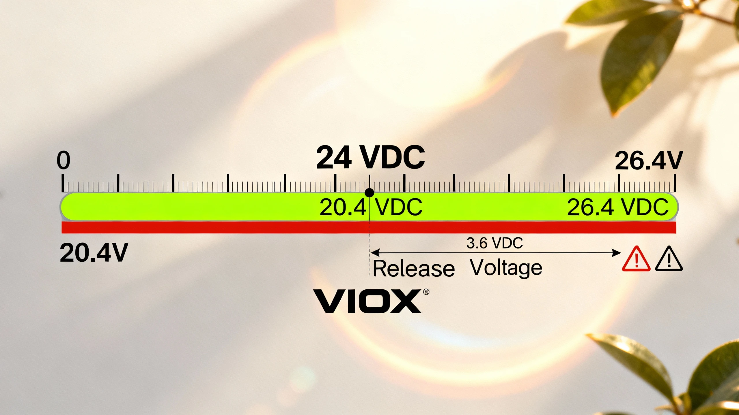
Nominale spanning is the nominal design voltage: 24 VDC, 120 VAC, 240 VAC/DC universal, etc. This is your reference point. But what matters operationally is the allowable supply voltage range of operating voltage range—typically 85% to 110% of rated voltage. A 24 VDC relay might specify 20.4–26.4 VDC operation. Stay within this window or the relay may malfunction.
Some relays offer wider ranges. Universal-input models might accept 12–240 VAC/DC, automatically adapting to whatever supply you connect. Check whether your specific model variant supports the voltage range, or if you need to order a different part number for each voltage.
Frequency rating matters for AC-powered relays: 50 Hz, 60 Hz, or 50/60 Hz. Most modern relays handle both frequencies, but older electromechanical designs may be frequency-sensitive.
Reset/Release Voltage
This specification defines the voltage threshold below which the relay reliably de-energizes and resets its timing circuit. Typical values are 10%–20% of rated voltage. For a 24 VDC relay with a 15% release voltage, the relay resets when supply drops below 3.6 VDC.
Why this matters: If your power supply experiences brownouts that dip to 50% of rated voltage but don’t go below the release threshold, the relay may not fully reset. Subsequent timing cycles could behave erratically because internal capacitors or logic didn’t fully discharge. Ensure your supply either stays above the minimum operating voltage or drops below the release voltage—don’t let it hover in the middle zone.
Input Threshold Levels (for Voltage-Input Relays)
Relays with separate start/trigger inputs specify high and low threshold voltages. A 24 VDC logic input might define “High” as ≥15 VDC and “Low” as ≤5 VDC, with a hysteresis band between 5–15 VDC. Your control signal must swing above the High threshold to guarantee recognition and below the Low threshold to reset.
Don’t assume a “24 VDC input” accepts 24 VDC logic levels. Some relays use 12 VDC thresholds even when powered by 24 VDC supply. Always check the input threshold specifications and verify your control circuit voltage compatibility.
Stroomverbruik
Datasheets list power consumption in watts or VA (for AC models). This figure accounts for the input circuit, timing electronics, and any indicator LEDs. Use maximum power consumption for power supply sizing, thermal calculations, and fuse/breaker selection. In large control panels with dozens of relays, power consumption adds up quickly—underestimating it leads to overloaded supplies and voltage sag under load.
Contact and Output Specifications
Contact specifications determine whether the relay can safely switch your load. Misreading these specs causes premature contact wear, welding, and field failures.
Contact Configuratie
Time relays typically offer SPDT (single-pole double-throw, 1 C/O contact) or DPDT (double-pole double-throw, 2 C/O contacts). Each pole provides one normally-open (NO) and one normally-closed (NC) contact sharing a common terminal. DPDT relays let you switch two independent loads or create redundant control circuits.
Some multifunction relays offer mixed configurations: one instantaneous contact (switches immediately when powered) and one timed contact (operates after the delay). Verify your model’s contact arrangement matches your control logic requirements.
Voltage and Current Ratings by Load Type
This is where most misapplication happens. Contact ratings are not universal—they depend heavily on load type, and datasheets publish separate ratings for different loads.
Resistive loads (heating elements, incandescent lamps, resistor banks) get the highest current ratings because they don’t generate voltage spikes or arc energy during switching. A relay might be rated 5 A at 250 VAC resistive and 5 A at 30 VDC resistive.
Inductive loads (solenoids, contactors, motor coils, transformers) generate back-EMF voltage spikes when switched, creating sustained arcing that erodes contacts. DC inductive loads are particularly harsh because DC arcs don’t self-extinguish at zero-crossing like AC arcs do. The same relay rated 5 A resistive might be limited to 0.1 A at 125 VDC inductive with L/R = 7 ms time constant. That’s a 50× derating. If you’re switching a 24 VDC solenoid, you might get 3 A; at 125 VDC, only 0.1 A.
AC utilization categories (per IEC standards) further refine ratings:
- AC-13: Control of electromagnetic loads (contactors, relay coils). Example: 5 A at 250 VAC.
- AC-15: Control of AC electromagnetic loads with holding current (auxiliary contacts). Example: 3 A at 250 VAC.
These categories account for inrush current, power factor, and duty cycle typical of each load type. Always select by the appropriate utilization category, not just the resistive rating.
Lamp loads and capacitive loads experience high inrush current during cold starts—incandescent lamps can draw 10–15× steady-state current for 10–100 milliseconds. Capacitor charging creates similar surges. Some datasheets include lamp load ratings; others require you to derate resistive ratings by 1/3 to 1/2. When in doubt, use soft-start circuits or specify relays with surge-rated contacts.
Mechanical and Electrical Endurance
Mechanical endurance (or mechanical life) specifies operations at no load—how many times the contacts can open and close before mechanical wear causes failure. Typical values: 10 million operations for quality relays, 1–5 million for economy models.
Electrical endurance (or electrical life) measures operations under rated load. This is always far lower than mechanical life because arcing and contact erosion accumulate with each switching event. A relay with 10 million mechanical operations might deliver only 100,000 electrical operations at rated resistive load, dropping to 30,000 operations for inductive loads.
Plan maintenance intervals based on electrical endurance for your actual load. If you’re switching a 2 A inductive load on a relay rated for 100,000 cycles at 5 A resistive but only 30,000 cycles at 3 A inductive, use the 30,000-cycle figure—or less, since you’re near the rated current limit.
Load Type Derating in Practice
Here’s a real-world example showing why load type matters:
Relay rating: 5 A at 250 VAC resistive; 0.1 A at 125 VDC inductive (L/R 7 ms); electrical life 100,000 operations at rated load.
Application 1: Switching a 120 VAC, 3 A heating element (resistive). The relay is well within its 5 A resistive rating. Expected life: 100,000+ cycles.
Application 2: Switching a 24 VDC, 2 A solenoid valve (inductive). The relay datasheet shows 3 A rating for 24 VDC inductive. Sounds fine—but check the electrical life derating for inductive loads. It might drop to 30,000 cycles, and at 2 A (67% of rated 3 A), expect further reduction to perhaps 40,000–50,000 cycles. Add a flyback diode across the solenoid to suppress back-EMF spikes and extend contact life significantly.
Application 3: Switching a 125 VDC, 0.5 A solenoid (inductive). The relay is rated only 0.1 A at 125 VDC inductive—you’re 5× over rating. Contacts will weld or erode within hundreds of cycles. Unacceptable. Either choose a relay with higher DC inductive ratings, use a solid-state output module instead of contacts, or add aggressive suppression and accept reduced life.
Environmental and Mechanical Ratings
Environmental specifications define the physical conditions under which the relay operates reliably. Installing a relay outside its environmental limits leads to premature failure, erratic timing, or safety hazards.
Operating and Storage Temperature
Bedrijfstemperatuurbereik (typical: −20°C to +60°C or −40°C to +70°C) defines ambient temperature limits during operation. Remember that “ambient” means air temperature around the relay, not panel or room temperature. Inside a crowded control cabinet with heat-generating equipment, ambient temperature near the relay can be 15–20°C higher than room temperature. Factor in heat rise when selecting relays for enclosed panels.
Temperatuurbereik bij opslag (typical: −40°C to +85°C) covers non-operating conditions. This matters for inventory stored in unheated warehouses or outdoor equipment sheds.
Temperature directly affects timing accuracy (via the temperature influence specification covered earlier). It also impacts contact materials, plastic housings, and electronic component life. Operating continuously at the upper temperature limit shortens component life even if the relay continues to function.
Humidity and Pollution Degree
Humidity ratings specify relative humidity limits without condensation, typically 25%–85% RH or 35%–95% RH. Condensing humidity (water droplets forming on the relay) is almost never acceptable unless the relay is specifically rated IP65 or higher for wet environments.
Vervuilingsgraad (per IEC 60664-1) classifies the relay’s resistance to conductive contamination:
- PD1: No pollution or only dry, non-conductive pollution (clean rooms, sealed enclosures).
- PD2: Normally only non-conductive pollution, with occasional temporary conductivity from condensation (typical offices, labs, light industrial).
- PD3: Conductive pollution, or dry non-conductive pollution that becomes conductive due to condensation (industrial environments, areas with dust, chemical exposure).
- PD4: Persistent conductive pollution from dust, rain, or other sources (outdoor exposed equipment, mines, harsh industrial).
Most control panel time relays are rated PD2. If you’re installing in industrial environments with metal dust, chemical vapors, or potential condensation, verify PD3 rating or use sealed/conformal-coated variants. Using a PD2 relay in a PD3 environment risks insulation breakdown and creepage failures—dangerous and code-violating.
Vibration and Shock Resistance
Vibration and shock specifications matter for mobile equipment, industrial machinery, and any installation subject to physical stress.
Trillingsweerstand is typically specified as a frequency sweep (e.g., 10–55 Hz) at a given amplitude (0.5–0.75 mm) or acceleration (1–5 g). Datasheets may list both “destruction” limits (vibration levels that cause physical damage) and “malfunction” limits (vibration levels that cause timing errors or contact bounce without permanent damage). Design your mounting to keep vibration below malfunction limits.
Shock resistance specifies acceleration levels the relay survives: 100–1,000 m/s² (10–100 g) for destruction, with lower values for malfunction. Half-sine pulse shocks simulate impact events like equipment drops or sudden machinery starts.
Relays mounted on DIN rail in rigid steel cabinets typically see minimal vibration. Relays on machinery frames, vehicle control panels, or equipment subject to impact require careful spec matching. Solid-state relays often have better vibration resistance than electromechanical types because they lack moving contacts.
Certifications and Standards References
Certifications prove the relay meets defined performance and safety requirements. Understanding what each marking means helps you verify compliance for your application and end-product certification.
IEC/EN 61812-1: The International Time Relay Standard
IEC 61812-1 is the global standard for time relays, covering timing accuracy, repeatability, electrical ratings, safety (dielectric strength, insulation), EMC immunity/emissions, and endurance testing. A relay marked “IEC 61812-1” or “EN 61812-1” (the European adoption) has passed type testing to these requirements.
When you see this marking, the datasheet should reference the standard’s classification framework: overvoltage category (typically Ov Cat II or III), pollution degree (PD2 or PD3), and rated impulse withstand voltage. These parameters tie directly to installation environment requirements—verify your panel or equipment environment matches the relay’s rated category.
For more detail on IEC 61812-1 requirements, see our companion article on IEC 61812-1 Standard & Compliance.
UL and cUL Recognition
UL 508 (Industrial Control Equipment) or UL 61810-1 (Electromechanical Elementary Relays) recognition is standard for North American markets. UL marks indicate the relay passed safety testing for electrical shock, fire hazard, and component reliability. “cUL” or “UL-C” indicates Canadian standards (CSA C22.2) compliance, often combined as “UL/cUL Listed” or “UL Recognized.”
UL recognition is component-level—it doesn’t certify your complete control panel, but it’s required for the panel to pass UL 508A certification. Always verify the specific model and voltage variant you’re specifying carries the UL mark; not all variants in a product family may be listed.
CE Marking and EMC Compliance
CE-markering indicates conformity to applicable EU directives, primarily the Low Voltage Directive (LVD) and EMC Directive. For CE marking on time relays, look for references to:
- EN 61812-1 (functional requirements and safety)
- EN 55011 of EN 55032 (radiated and conducted emissions limits)
- EN 61000-6-2 (EMC immunity for industrial environments) or EN 61000-6-1 (residential)
- EN 61000-3-2/-3 (harmonics and flicker limits)
The datasheet should list the specific EMC environment the relay is tested for—industrial (Class A emissions, higher immunity) or residential/commercial (Class B emissions, lower immunity). Don’t install an industrial-rated relay in residential applications without verifying emissions compliance, and vice versa.
Other Regional Marks
Depending on target markets, datasheets may show additional marks:
- CCC (China Compulsory Certificate)
- EAC (Eurasian Conformity, for Russia/Kazakhstan/Belarus)
- RCM (Regulatory Compliance Mark, Australia/New Zealand)
- UKCA (UK Conformity Assessed, post-Brexit UK)
These regional marks don’t change relay performance, but they’re required for legal sale and installation in those markets.
How to Compare Datasheets from Different Manufacturers
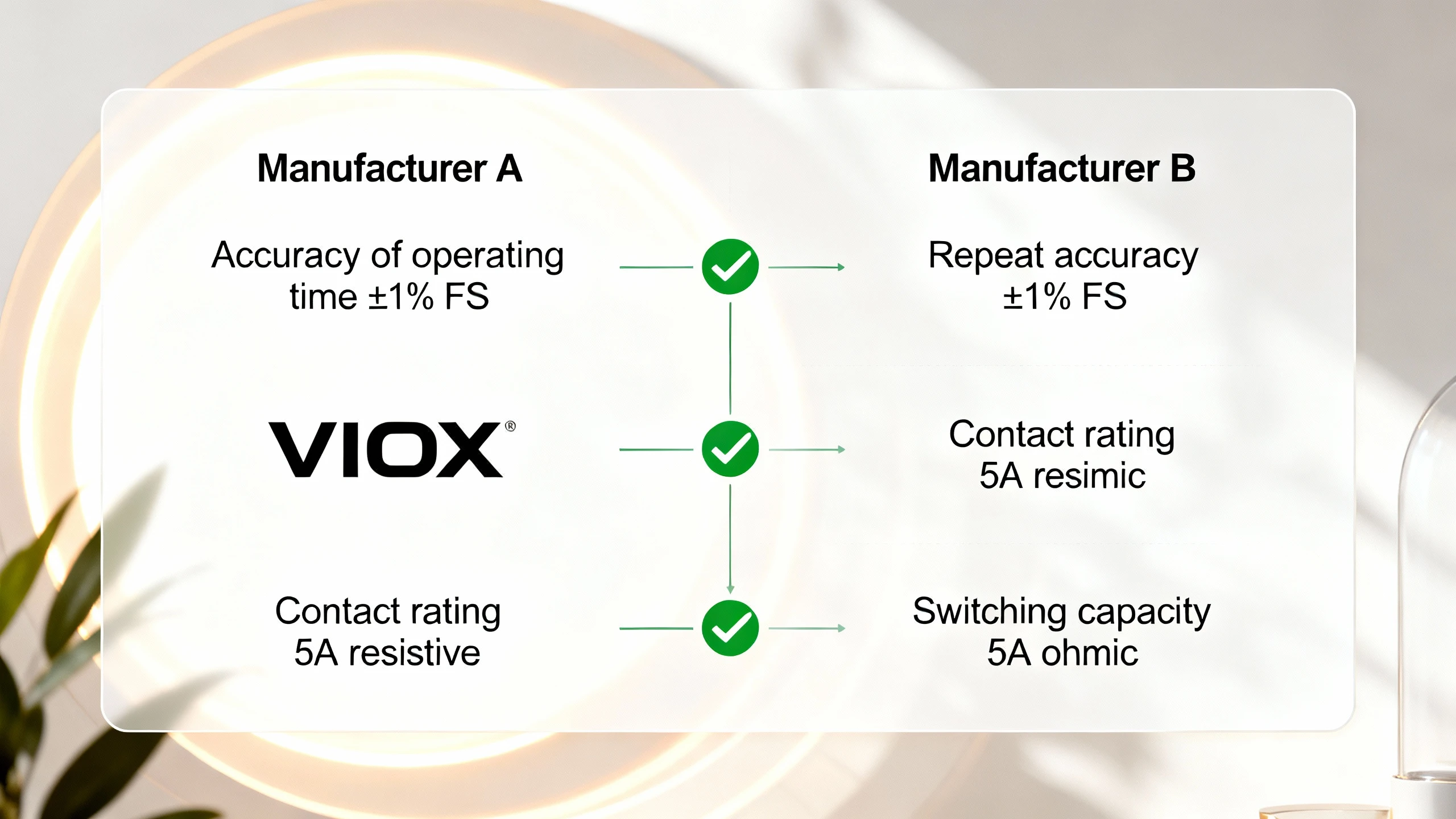
Comparing relay datasheets across manufacturers requires recognizing that terminology and presentation vary even when the underlying specifications are equivalent. Here’s how to make apples-to-apples comparisons.
Timing Accuracy Terminology Differences
One manufacturer might list “Accuracy of operating time: ±1% FS” alongside separate “Influence of voltage: ±0.5% FS” and “Influence of temperature: ±2% FS.” Another might combine everything into “Repeat accuracy: ±3.5% FS” without breaking out the components. Both are describing the same total timing tolerance, just packaged differently.
When you see separate influence quantities listed, add them to get total worst-case error (assuming worst-case voltage and temperature simultaneously). When you see a single combined accuracy figure, that’s already your total band—but you can’t tell how much comes from voltage vs. temperature effects.
Setting Range Notation
Time ranges might be shown as “0.1–1.2 s, 1–12 s, 10–120 s” (explicit ranges) or “0.1 s, 1 s, 10 s scales” (implying 1.2× multiplier). Both mean the same thing if the multiplier is standard, but always verify the actual settable range rather than assuming.
Contact Rating Presentation
Some datasheets show detailed load-type tables (resistive, AC-13, AC-15, DC inductive at multiple voltages and L/R values). Others give only resistive ratings with a footnote: “Derate for inductive loads per IEC standards.” The first approach is more useful because it eliminates guesswork, but both are technically valid.
When comparing:
- Identify equivalent load types: Match resistive-to-resistive, AC-13-to-AC-13, DC inductive at same voltage and L/R.
- Check voltage ratings: A 5 A rating at 250 VAC isn’t directly comparable to 5 A at 120 VAC—higher voltage increases arc energy and stress.
- Compare electrical endurance at rated load: A relay rated 100,000 operations may outlast one rated 50,000 operations even at identical current ratings.
Power Consumption Units
AC relays often list power consumption in VA (volt-amperes) because coil circuits have power factor <1. DC relays use watts. To compare across types, convert VA to approximate watts by assuming power factor 0.5–0.7 for AC coils: 5 VA ≈ 2.5–3.5 W. For power supply sizing, use VA directly for AC and watts for DC.
Environmental Specs: Watch the Details
Operating temperature ranges look similar until you check the fine print. One relay might specify “−20 to +60°C” with full timing accuracy; another might list “−40 to +70°C” but note “timing accuracy guaranteed only 0 to +50°C.” The second relay has a wider survivable range but narrower performance range.
Similarly, vibration specs matter only if test conditions are comparable. “10–55 Hz, 0.75 mm amplitude” and “10–55 Hz, 2 g acceleration” aren’t directly equivalent without knowing the frequency-amplitude relationship.
When “Equivalent” Specs Aren’t
Two relays might both claim “±1% timing accuracy,” “5 A contact rating,” and “IEC 61812-1 compliant,” yet perform very differently because:
- The ±1% might be at different full-scale bases (one at 12 s, another at 10 s).
- The 5 A rating might be resistive-only vs. including AC-15 inductive.
- IEC compliance might be self-declared vs. third-party certified.
- Electrical endurance might differ by 3× (30,000 vs. 100,000 cycles).
- One might have better EMC immunity (industrial vs. residential test levels).
Always dig into the detailed spec tables, not just the headline numbers. Compare full specifications in the same application context: your actual load type, voltage, temperature range, and duty cycle.
Application-Specific Selection Tips
Different applications prioritize different datasheet specifications. Here’s what matters most for common time relay use cases.
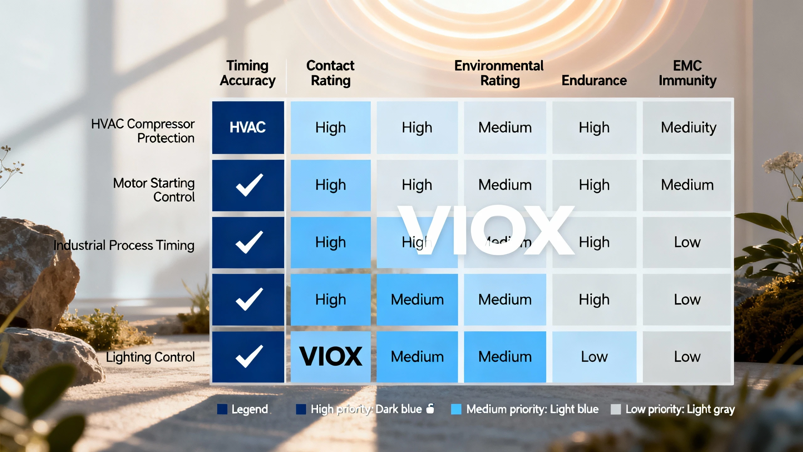
HVAC Compressor Protection (Off-Delay)
Critical specs: Timing accuracy and repeatability (typically ±5–10% acceptable for 3–5 minute short-cycle protection), contact rating for compressor contactor coil (AC-13 category, usually 3–5 A at 120/240 VAC), operating temperature range (HVAC equipment spaces can reach 50°C+), and electrical endurance (100,000+ cycles for long service life).
Less critical: Sub-second timing precision, input pulse width (HVAC controls use sustained signals).
Motor Starting Sequence Control (On-Delay, Star-Delta)
Critical specs: Timing accuracy at short ranges (1–10 seconds typically, need ±2–3% or better for coordinated starting), repeatability (cycle-to-cycle consistency prevents motor stress), contact ratings for motor starter coils (AC-13, check inrush), and vibration resistance if mounted on machinery.
Less critical: Long time ranges (hours), ultra-wide voltage range.
Industrial Process Timing (Interval, Repeat Cycle)
Critical specs: High timing accuracy and repeatability (±1% FS or better for coordinated processes), wide operating temperature and pollution degree (PD3 for industrial environments), electrical endurance for high-cycle applications, and EMC immunity (industrial test levels to resist VFD noise).
Less critical: Multi-voltage capability if power supply is standardized.
Lighting Control (Off-Delay for Run-On)
Critical specs: Timing range matching application (30 seconds to 10 minutes common), contact rating for lighting loads (check lamp load derating or use AC-15 ratings), mechanical endurance (daily cycling adds up), and physical size/mounting (often space-constrained in lighting panels).
Less critical: Millisecond timing precision, harsh industrial ratings (most lighting is in controlled environments).
General Selection Hierarchy
For most applications, prioritize specs in this order:
- Timing function and range: Does it do what you need?
- Contact ratings for your actual load: Prevents premature failure.
- Timing accuracy/repeatability: Ensures performance meets requirements.
- Environmental ratings: Ensures survival in installation environment.
- Electrical ratings: Supply voltage compatibility and input thresholds.
- Certificeringen: Required for compliance and marketability.
- Physical form factor: Must fit your panel/enclosure.
- Endurance and MTBF: Affects maintenance intervals.
- Features and adjustability: Nice-to-have convenience (digital display, programmability).
- Prijs: Consider total cost including installation labor and service life.
Reading VIOX Time Relay Datasheets
VIOX time relay datasheets follow the IEC 61812-1 structure and present specifications in the format described throughout this guide. Our datasheets prioritize clarity and completeness—every specification needed for proper selection is documented in accessible tables.
Key features of VIOX datasheets:
- Timing specifications are presented with explicit full-scale accuracy, repeatability, and separate influence of voltage/temperature quantities—no guesswork on tolerance stacking.
- Contact beoordelingen include detailed tables for resistive, AC-13, AC-15, and DC inductive loads at multiple voltages with specific L/R values. We don’t hide critical derating information in footnotes.
- Environmental ratings clearly state operating vs. performance ranges—when temperature limits affect timing accuracy, we specify both the survivable range and the guaranteed-performance range.
- Certificeringen are documented with certificate numbers and dates. IEC 61812-1, UL 508, and CE compliance are backed by third-party test reports available on request.
- Application examples and wiring diagrams show real-world installation contexts to reduce design time and prevent common wiring errors.
All VIOX time relay product pages link to downloadable PDF datasheets, CAD models, and compliance certificates. For technical support interpreting specifications for your specific application, contact our application engineering team.
Conclusion: From Specifications to Confident Selection
Time delay relay datasheets contain everything you need to select the right product—but only if you know how to extract and interpret the information. Understand timing accuracy on a full-scale basis, contact derating for your load type, environmental limits matching your installation, and influence quantities that affect real-world performance. Get these right, and you avoid costly misapplication.
The most common mistakes—assuming resistive contact ratings apply to inductive loads, overlooking minimum input pulse width, ignoring temperature influence on timing accuracy, misunderstanding full-scale vs. set-value accuracy—all stem from skimming datasheets rather than reading them systematically. Take the time to verify every specification that affects your application. Check not just the headline numbers but the test conditions, derating factors, and environmental qualifiers.
When comparing relays from different manufacturers, recognize that terminology varies even when underlying performance is equivalent. Translate specs into common terms: total worst-case timing error, contact rating at your specific load type and voltage, performance limits under your actual environmental conditions. Don’t rely on marketing summaries—dig into the detailed specification tables.
Datasheets are decision tools. Used correctly, they prevent costly misapplication, reduce field failures, and ensure your time delay relays deliver reliable performance throughout their service life. The control panel builder from our opening example learned this the expensive way—you don’t have to.
