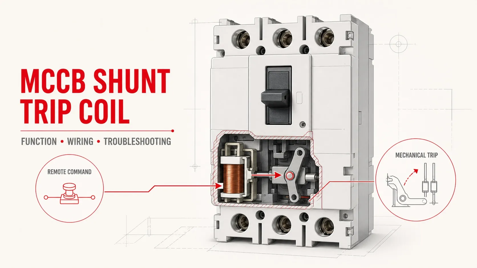
An MCCB shunt trip coil is an electrically operated accessory that opens a molded case circuit breaker when an external control voltage is applied. It allows an MCCB to be tripped by a remote push button, safety relay, fire-alarm interface, programmable logic controller (PLC), or another control system.
The shunt trip does not measure overload or short-circuit current, and it does not replace the MCCB trip unit. Its job is simpler: convert an external electrical command into a mechanical trip of the breaker. Reliable operation depends on four things—compatibility with the exact MCCB, the correct coil voltage, a correctly designed command circuit, and a verified functional test.
Safety note: MCCB installation, accessory wiring, and energized testing should be performed only by qualified personnel under the applicable lockout/tagout procedure. Always follow the instructions for the exact breaker and shunt release. Terminal markings and permitted control-circuit arrangements vary by manufacturer and product family.
Key Takeaways
- A shunt trip is normally an energize-to-trip accessory: applying the specified control voltage causes the MCCB to open.
- It is separate from the MCCB’s thermal-magnetic or electronic protection functions.
- The accessory must match the breaker family, frame size, control voltage, AC/DC type, frequency where applicable, and permitted duty.
- A shunt trip and an undervoltage release solve different control problems. Loss of shunt-trip control power does not normally trip the breaker; loss of undervoltage-release power does.
- Do not assume that a coil can remain energized continuously. Confirm whether the selected accessory accepts a pulse, a maintained command, or both.
- A complete commissioning test checks the control voltage at the accessory and confirms that the breaker trips, indicates the tripped state, resets, and can be returned to service only after the trip command is cleared.
What Is a Shunt Trip Coil in an MCCB?
A molded case circuit breaker protects a circuit against defined overcurrent conditions through its trip unit. A shunt trip coil, also called a shunt release or shunt opening release, adds an independent way to operate the breaker’s trip mechanism.
When the shunt release receives a valid command voltage, its electromagnetic mechanism acts on the MCCB’s internal trip bar or latch. The breaker contacts open, interrupting the protected circuit. The breaker must then be reset according to its normal operating procedure after the cause of the trip has been investigated and the external command has been removed.
If you need a broader explanation of frames, trip units, interrupting ratings, and MCCB selection, see the VIOX guide to molded case circuit breakers. This article focuses only on the shunt-trip accessory and its control circuit.
What the shunt trip does not do
A shunt trip coil does not:
- detect overload current by itself;
- calculate short-circuit protection settings;
- provide ground-fault sensing unless it receives a command from a separate sensing or protection device;
- guarantee fail-safe operation after loss of control power;
- make an incompatible MCCB suitable for remote tripping;
- replace the need to select the correct MCCB interrupting and current ratings.
This distinction matters because the term “trip coil” is sometimes used loosely. The MCCB trip unit decides whether an electrical fault requires interruption. The shunt release responds to an external command.
How an MCCB Shunt Trip Coil Works
The operating sequence is straightforward:
- The MCCB is closed and its mechanical trip mechanism is latched.
- An external device closes the shunt-trip command circuit.
- The specified control voltage appears across the shunt release terminals.
- Current through the coil creates a magnetic field.
- The armature or plunger operates the internal trip linkage.
- The MCCB mechanism releases and the main contacts open.
- The handle or position indicator moves to the breaker’s tripped state.
- After the cause is cleared and the command is removed, the breaker is reset—commonly by moving the handle fully to OFF before reclosing, subject to the manufacturer’s instructions.
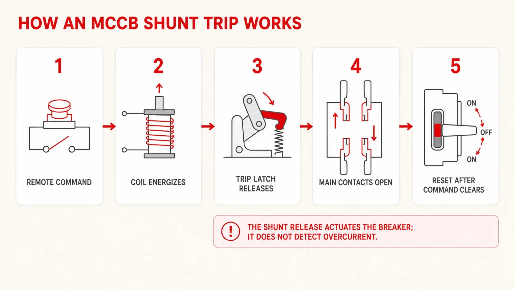
This is an electrical command acting on a mechanical latch. A correct voltage at the coil does not guarantee a trip if the accessory is incorrectly installed, mechanically obstructed, incompatible with the frame, or connected to the wrong terminals.
Pulse command or maintained command?
Some shunt releases can operate from a short command pulse; some product families also permit a maintained command. For example, Schneider Electric documents impulse-type or maintained operation for the MX release in the cited breaker family. That does not mean every MCCB shunt coil is continuous-duty.
Before designing the control circuit, confirm:
- the minimum permitted command duration;
- whether a maintained signal is allowed;
- whether an internal cut-off contact removes coil power after tripping;
- whether an external auxiliary contact must interrupt the command;
- the accessory’s operating-voltage range;
- the coil’s AC/DC and frequency requirements.
If the documentation is unclear, treat continuous energization as unverified. A coil intended for momentary operation may overheat or fail if it remains powered.
Shunt Trip, Shunt Release, MX and SHT: Terminology Explained
Manufacturers do not all use the same accessory codes. The following terms commonly describe the same general energize-to-trip function, but they are not interchangeable part numbers.
| Term | Typical meaning | Important limitation |
|---|---|---|
| Shunt trip | Remote electrically initiated opening function | Generic functional term |
| Shunt trip coil | Electromagnetic operating element of the shunt-trip accessory | May refer to the coil or the complete accessory |
| Shunt release | Complete electrical release installed in the breaker | Common IEC-oriented wording |
| Shunt opening release | Release used to open, not close, the breaker | Avoid confusing it with a closing release |
| MX | Schneider Electric designation used for certain shunt releases | Not a universal terminal or accessory code |
| SHT | Shunt-trip abbreviation used by some manufacturers | Exact meaning must be checked in the product manual |
| Trip coil | Broad term that may also be used for mechanisms in other breaker types | Confirm whether the document means an MCCB accessory |
Search terms such as shunt coil in MCCB, MCCB shunt trip, and shunt release in MCCB often point to the same functional question. Selection, however, must be based on the manufacturer’s exact catalog code—not the generic name.
Basic MCCB Shunt Trip Wiring Logic
A basic remote-trip circuit contains a control supply, control-circuit protection, one or more command contacts, and the shunt release.
Control L / +
    |
    +-- Control-circuit protection
    |
    +-- Permissive or healthy-chain contacts, if required
    |
    +-- NO TRIP push button / relay output contact
    |
    +-- Shunt trip release
    |
Control N / -
Pressing the normally open (NO) trip button—or closing the relay contact—completes the circuit and energizes the shunt release. The MCCB then opens if the control voltage, accessory installation, and mechanism are correct.
This diagram explains the logic only. It is not a substitute for the accessory wiring diagram. The final design must verify polarity, terminal identification, control protection, conductor sizing, command duration, and isolation requirements.
Preventing unintended continuous energization
Where the selected release is not approved for a maintained command, the designer may use a breaker auxiliary contact or another control relay to remove power after the breaker trips. The selected contact must change state in the required breaker position and be rated for the control circuit.
Do not assume that any auxiliary contact marked “open” or “closed” performs this function. Manufacturers may provide separate contacts for breaker position, trip indication, or accessory control.
Wiring a shunt trip to a fire-alarm or safety system
A fire-alarm panel, emergency-stop circuit, gas-detection system, building-management system, or safety relay may provide the trip request. The interface must be engineered rather than connected by name alone.
Check these questions first:
| Design question | Why it matters |
|---|---|
| Does the command source provide a dry contact or a powered output? | A powered output may not match the coil voltage or polarity |
| Can the source contact switch the coil’s required load? | An interposing relay may be needed |
| Must the circuit be supervised for open- or short-circuit faults? | A basic shunt-trip loop may not provide supervision |
| Is loss of control power required to trip the breaker? | If yes, an undervoltage release or another fail-safe architecture may be more appropriate |
| Must selected loads remain energized during an emergency? | The shutdown sequence may require multiple breakers, time delays, or selective load shedding |
| How will the system be reset and tested? | The trip command must clear before the MCCB can be safely returned to service |
Never connect a shunt release directly to a fire-alarm output unless the interface is permitted by the alarm equipment, breaker manufacturer, applicable code, and approved system design.
PLC or control-relay interface
A PLC output usually should not be assumed capable of driving a shunt coil directly. Verify the output type, maximum voltage, current, inrush capability, isolation, and required suppression for inductive loads. An interposing relay is commonly used when the output and coil are electrically incompatible or when additional isolation is required.
For DC coils, any suppression component must be selected carefully. Incorrect suppression can slow current decay or interfere with the required release response. Follow the MCCB/accessory and control-device manufacturer’s recommendations.
Shunt Trip vs. Undervoltage Release
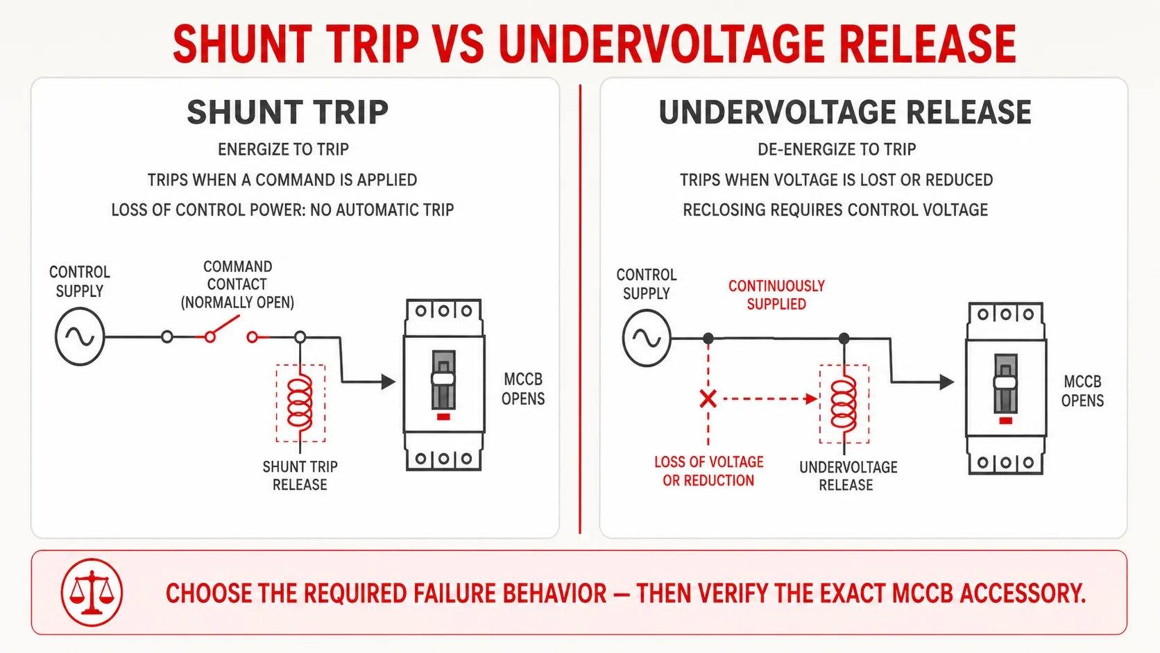
The most important design distinction is the response to control power.
| Criterion | Shunt trip release | Undervoltage release |
|---|---|---|
| Operating principle | Energize to trip | De-energize or reduce voltage to trip |
| Normal coil state | Commonly de-energized until a trip command | Commonly energized while operation is permitted |
| Loss of control power | Normally does not initiate a trip by itself | Causes or permits the breaker to trip according to the release’s voltage thresholds |
| Reclosing behavior | Breaker can generally be reset after the trip command is removed | Reclosing is inhibited until sufficient control voltage returns |
| Typical use | Remote shutdown command, process interlock, alarm-initiated trip | Fail-safe emergency stop, loss-of-voltage protection, prevention of automatic restart |
| Common manufacturer code | MX or SHT on some product families | MN or UVR on some product families |
The correct choice depends on the required failure behavior. If a broken control wire or lost supply must force the breaker open, a simple shunt-trip circuit may not meet that requirement. An undervoltage release is designed around the opposite operating philosophy.
Manufacturer thresholds are product-specific. In Schneider Electric’s cited ComPacT NSXm documentation, the MX shunt trip is described as tripping above a defined fraction of rated control voltage, while the MN undervoltage release responds when its supply falls into specified low-voltage ranges. Do not apply those numerical thresholds to another MCCB family without its documentation.
How to Select a Shunt Trip Coil for an MCCB
The accessory name is only the starting point. Use the following specification checklist.
| Selection item | What to verify | Common mistake |
|---|---|---|
| MCCB family and frame | Exact breaker series, frame size, pole configuration, and accessory cavity | Ordering a coil that fits a different frame from the same brand |
| Accessory function | Shunt trip/opening release rather than undervoltage or closing release | Selecting by a similar-looking module |
| Rated control voltage | Exact voltage range on the accessory label and datasheet | Using nominal panel voltage without checking the coil |
| Supply type | AC or DC; frequency for AC versions | Treating equal numerical voltages as interchangeable |
| Command duration | Pulse, maintained command, or both | Holding a momentary-duty coil energized |
| Command source | Push button, relay, PLC, fire-alarm interface, or safety system | Driving the coil from an underrated output |
| Auxiliary contacts | Position feedback, trip indication, or coil cut-off function | Assuming one contact can serve every purpose |
| Installation method | Factory-fitted or field-installable; correct internal position | Forcing an incompatible accessory into the breaker |
| Documentation | Wiring diagram, accessory instructions, approvals, and test procedure | Relying on generic online diagrams |
| Replacement identity | Full catalog number and revision compatibility | Replacing only by coil voltage or appearance |
VIOX offers multiple MCCB product families. Before selecting an accessory, provide the breaker model, frame size, control voltage, command source, required failure behavior, and applicable market or standard.
Typical Applications of an MCCB With Shunt Trip Coil
Remote emergency shutdown
A remote push button can trip an MCCB when the breaker is difficult or unsafe to approach. The complete emergency-stop function must still be evaluated for required reliability, supervision, reset behavior, and failure response.
Fire-alarm-initiated power isolation
A fire-alarm interface may command selected nonessential loads to disconnect. The breaker is only one part of the sequence; the system design must define which loads are disconnected, which remain energized, and how feedback is monitored.
Process and machinery interlocks
A protection relay, safety controller, or process system can trip an upstream MCCB when a defined hazardous condition occurs. The shunt release provides the actuation path but does not perform the sensing logic.
Remote operator or SCADA command
Supervisory systems may initiate a trip through an isolated relay output. Because remote commands can be issued without a person at the equipment, designs should include appropriate authorization, indication, event recording, and safe reset procedures.
Generator, UPS, and transfer-system logic
Power-system controls may open an MCCB as part of source transfer, load shedding, or abnormal-condition response. Coordination with interlocks and downstream equipment is essential; adding a shunt trip alone does not create a complete transfer scheme.
Commissioning an MCCB Shunt Trip
A functional test should prove the entire command path, not only coil continuity.
Pre-energization checks
- Confirm the MCCB and release catalog numbers are compatible.
- Verify the accessory is fully seated and mechanically secured.
- Compare the control supply with the accessory label, including AC/DC type and frequency.
- Check the wiring against the product diagram.
- Confirm control-circuit protection and isolation.
- Verify that no maintained trip command is present unless the accessory permits it.
- Establish a safe test condition so opening the breaker will not create a new hazard.
Functional trip test
The basic manufacturer test logic is:
- Close the MCCB in a safe test condition.
- Apply the intended trip command through the normal control path.
- Confirm that the MCCB opens and indicates the expected state.
- Verify that the command voltage is removed or permitted to remain, according to the accessory design.
- Clear the trip command.
- Reset the breaker according to the manufacturer’s procedure.
- Confirm any position, trip, or alarm feedback changes correctly.
Testing only at the coil terminals can miss failures in the push button, relay, PLC logic, fire-alarm interface, control fuse, auxiliary contact, or field wiring. Where the system depends on the complete chain, test the complete chain.
Troubleshooting: MCCB Shunt Trip Coil Does Not Operate
Before opening a panel or measuring a control circuit, isolate hazardous energy and follow the approved test procedure.
| Symptom | Likely cause | What to check | Corrective action |
|---|---|---|---|
| MCCB does not trip and no control voltage reaches the release | Open control fuse, wiring fault, open permissive contact, failed push button, or missing PLC/relay command | Measure at defined test points and trace the command path | Restore the control circuit; replace the failed control component |
| Correct voltage reaches the release but MCCB does not trip | Incompatible accessory, incorrect installation, open coil, jammed plunger, or breaker mechanism fault | Verify catalog numbers, seating, coil continuity per manufacturer data, and mechanical condition | Reinstall correctly or replace the specified accessory/breaker component |
| Voltage at the coil is below the permitted operating range | Excessive voltage drop, undersized control supply, long cable, poor connection, or overloaded output | Measure voltage at the release while the command is active | Correct the supply, connection, conductor, or interface design |
| Coil becomes hot, smells damaged, or fails repeatedly | Incorrect voltage, wrong AC/DC type, sustained energization, or excessive command repetition | Compare actual supply and command duration with the accessory data | De-energize and replace damaged parts; correct the circuit before retesting |
| Breaker trips locally but not from the fire alarm or PLC | Interface mismatch, wrong output logic, insufficient contact rating, or missing interposing relay | Test the release from an approved local control source, then test the interface separately | Correct the interface and isolation arrangement |
| Breaker trips but cannot be reset | Trip command still present, undervoltage release not energized, mechanism not fully reset, or underlying fault remains | Check control states, accessory type, indication, and breaker reset procedure | Remove the command, restore required control voltage, clear the fault, and reset correctly |
| Nuisance trips occur | Intermittent command, induced voltage, wiring insulation fault, control-logic error, or incorrect accessory | Review event logs and monitor the control circuit at the time of the trip | Repair wiring, correct logic, and verify accessory identity |
| Remote trip works but status feedback is wrong | Incorrect auxiliary-contact selection or wiring | Compare the contact function with the breaker state table | Rewire or select the correct position/trip indication contact |
Why a resistance test is not enough
A continuity or resistance check can identify an obviously open coil, but it cannot prove that the armature moves, the accessory is installed correctly, or the breaker latch releases. Resistance values also vary between coil voltages and designs. Use the manufacturer’s expected values where provided, then complete a controlled functional test.
When to replace rather than continue testing
Stop and replace or escalate the accessory when you find visible heat damage, melted insulation, a cracked housing, an open winding, incorrect mechanical fit, repeated failure at the correct control voltage, or an accessory catalog number that is not approved for the breaker. Do not rewind, modify, or mechanically adapt a safety-related release unless the manufacturer explicitly provides such a repair method.
Common Design and Installation Mistakes
Selecting by voltage alone
Two shunt coils with the same voltage are not necessarily interchangeable. Mechanical dimensions, trip linkage, connectors, accessory coding, and breaker-frame compatibility can differ.
Confusing shunt trip with fail-safe undervoltage operation
A shunt trip needs an active command. A broken wire can prevent that command from reaching the coil. Where loss of control power must cause opening or prevent closure, evaluate an undervoltage release and the complete safety architecture.
Driving the coil directly from a PLC output
The output may have insufficient current capacity, the wrong voltage, inadequate isolation, or unsuitable protection for an inductive load. Use a correctly selected interposing device when required.
Leaving a momentary-duty coil energized
A latched relay output or maintained push button can keep voltage on the release. Confirm the permitted duty and provide a cut-off arrangement where required.
Omitting feedback
A command proves only that the control system requested a trip. It does not prove that the MCCB opened. Where the system needs confirmation, use the manufacturer’s appropriate breaker-position or trip-indication contact and verify it during commissioning.
Testing only the breaker accessory
An accessory test bypassing the normal command chain can leave a failed alarm contact, relay, PLC output, or field cable undiscovered. Test locally for diagnosis, then test the complete system before return to service.
Frequently Asked Questions
What is a shunt trip coil in an MCCB?
It is an electrical release installed in or on a compatible molded case circuit breaker. Applying the specified control voltage operates the breaker’s trip mechanism and opens the main contacts.
Is a shunt trip coil normally energized?
Typically, a shunt trip is de-energized until an opening command is required. Some accessories permit a maintained command, while others require a pulse or external cut-off. Confirm the duty in the exact accessory documentation.
Does an MCCB shunt trip work without control power?
No. A shunt trip needs a valid electrical command. Loss of its control supply does not normally trip the breaker. If loss of voltage must initiate opening or prevent reclosing, an undervoltage release may be the appropriate accessory.
Can a shunt trip coil be connected directly to a PLC?
Only if the PLC output is compatible with the coil voltage, current, load type, isolation, and protection requirements. An interposing relay is often used, but the correct interface depends on both manufacturers’ data.
Can a fire alarm trip an MCCB?
Yes, a listed or approved interface can command a compatible shunt release. The shutdown sequence, output rating, circuit supervision, reset logic, and loads that must remain energized must be defined by the applicable system design and code requirements.
What is the difference between a shunt trip and an undervoltage release?
A shunt trip opens the MCCB when its coil is energized. An undervoltage release opens—or prevents closure—when its supply voltage is lost or falls below the device’s specified operating range.
Why does the MCCB trip but refuse to close again?
The external trip signal may still be active, an undervoltage release may lack its required supply, the breaker may not have been fully reset, or the original fault condition may still exist. Check the accessory type, control state, indication, and manufacturer reset procedure before attempting to reclose.
How do you test an MCCB shunt trip coil?
Verify compatibility and wiring, place the system in a safe test condition, close the MCCB, apply the normal trip command, and confirm that the breaker opens and provides the expected indication. Clear the command and reset the breaker only after the cause and circuit state are safe.
Conclusion
An MCCB shunt trip coil provides a direct path from an external control decision to breaker opening. The concept is simple, but a dependable installation requires more than connecting two wires. The release must fit the exact breaker, match the control supply, receive a valid command for the permitted duration, and be tested through the complete operating chain.
For engineering or procurement, specify the MCCB model and frame, shunt-release catalog number, control voltage and supply type, command source, required failure behavior, auxiliary-contact needs, and applicable documentation. That information prevents the most common causes of a shunt trip MCCB failing when a remote opening command is needed.