
உங்கள் ஸ்மார்ட்போன் சார்ஜரை சுவரில் செருகும்போதோ, மடிக்கணினியை சார்ஜ் செய்யும்போதோ அல்லது லைட் சுவிட்சை மாற்றும்போதோ, நீங்கள் இதுவரை கண்டுபிடிக்கப்பட்ட மிகவும் புத்திசாலித்தனமான மின் சாதனங்களில் ஒன்றை நம்பியிருக்கிறீர்கள்: மின்மாற்றி. மின்சார உலகின் இந்த அமைதியான வேலைக்காரர்கள், மின் கம்பிகள் வழியாக பயணிக்கும் உயர் மின்னழுத்த மின்சாரம் உங்கள் வீட்டில் உள்ள சாதனங்களுக்கு பாதுகாப்பாக மின்சாரம் வழங்குவதை சாத்தியமாக்குகின்றன.
ஆனால் ஒரு மின்மாற்றி எவ்வாறு செயல்படுகிறது?? பதில் கிட்டத்தட்ட 200 ஆண்டுகளுக்கு முன்பு கண்டுபிடிக்கப்பட்ட ஒரு கண்கவர் கொள்கையில் உள்ளது, அது நமது நவீன உலகிற்கு தொடர்ந்து சக்தி அளிக்கிறது. இந்த விரிவான வழிகாட்டியில், மின்மாற்றிகள் எவ்வாறு சரியாக வேலை செய்கின்றன, அவை மின்சக்தி விநியோகத்திற்கு ஏன் அவசியம், மற்றும் மின்காந்த தூண்டலின் கொள்கை எவ்வாறு இதை சாத்தியமாக்குகிறது என்பதை நீங்கள் கண்டுபிடிப்பீர்கள்.
நீங்கள் மின் பொறியியல் பற்றி கற்றுக்கொள்ளும் மாணவராக இருந்தாலும் சரி, ஆர்வமுள்ள வீட்டு உரிமையாளராக இருந்தாலும் சரி, அல்லது புதுப்பித்தல் தேடும் நிபுணராக இருந்தாலும் சரி, இந்த வழிகாட்டி அடிப்படைக் கருத்துகளிலிருந்து மேம்பட்ட பயன்பாடுகள் வரை உங்களை அழைத்துச் செல்லும் - அனைத்தும் தெளிவான, அணுகக்கூடிய மொழியில் விளக்கப்பட்டுள்ளன.
எளிய பதில்: மின்மாற்றிகள் "காந்த மந்திரத்தை" பயன்படுத்துகின்றன.
உங்கள் குழாய்களில் உள்ள மின்னழுத்தம், நீர் அழுத்தம் போன்றது என்று நினைத்துப் பாருங்கள். தோட்டத் தெளிப்பானைப் பாதுகாப்பாக உயர் அழுத்த பிரதான பாதையுடன் இணைக்க உங்களுக்கு ஒரு அழுத்தக் குறைப்பான் தேவைப்படலாம் என்பது போல, மின்சார மின்மாற்றிகள் வேலை செய்கின்றன மின்சாரத்தைப் பாதுகாப்பானதாகவும் வெவ்வேறு பயன்பாடுகளுக்குப் பயன்படுத்தக்கூடியதாகவும் மாற்ற மின்னழுத்த அளவை மாற்றுவதன் மூலம்.
இதோ எளிய பதிப்பு: மின்மாற்றிகள் மின்னழுத்தத்தை மாற்றும் அதே வேளையில் ஒரு சுற்றிலிருந்து மற்றொரு சுற்றுக்கு மின் ஆற்றலை மாற்ற மின்காந்த தூண்டலைப் பயன்படுத்துகின்றன.. அவர்கள் இந்த குறிப்பிடத்தக்க சாதனையை எந்த நகரும் பாகங்களும் இல்லாமல் செய்கிறார்கள், மின்னழுத்த அளவை "மேலே" அல்லது "கீழ்நோக்கி" குறைக்க காந்தத்தின் கண்ணுக்குத் தெரியாத சக்தியை மட்டுமே பயன்படுத்துகிறார்கள்.
ஒரு கம்பிச் சுருள் வழியாகப் பாயும் மாற்று மின்னோட்டம், முற்றிலும் தனித்தனியான ஒரு இரண்டாவது சுருளில் மின்னழுத்தத்தைத் தூண்டும் ஒரு மாறிவரும் காந்தப்புலத்தை உருவாக்கும்போது "மாயாஜாலம்" நிகழ்கிறது. நேரடி மின் இணைப்பு தேவையில்லை - 1831 இல் மைக்கேல் ஃபாரடே கண்டுபிடித்த மின்காந்த தூண்டலின் சக்தி மட்டுமே.
ஆனால் இங்கேதான் சுவாரஸ்யமாகிறது: சரியான மின்னழுத்த மாற்றம் இரண்டு சுருள்களுக்கு இடையிலான கம்பி திருப்பங்களின் எளிய விகிதத்தைப் பொறுத்தது. அதிக திருப்பங்கள் என்றால் அதிக மின்னழுத்தம்; குறைவான திருப்பங்கள் என்றால் குறைந்த மின்னழுத்தம். இந்த நேர்த்தியான எளிமை ஒரு நூற்றாண்டுக்கும் மேலாக மின்மாற்றிகளை இன்றியமையாததாக ஆக்கியுள்ளது.
அடித்தளம்: மின்காந்த தூண்டலைப் புரிந்துகொள்வது
உண்மையிலேயே புரிந்து கொள்ள மின்சார மின்மாற்றிகள் எவ்வாறு செயல்படுகின்றன1831 ஆம் ஆண்டு பிரிட்டிஷ் விஞ்ஞானி மைக்கேல் ஃபாரடே உலகைப் புரட்சிகரமாக்கும் ஒரு கண்டுபிடிப்பைச் செய்தபோது, நாம் அதற்குத் திரும்பிச் செல்ல வேண்டும். ஃபாரடே குறிப்பிடத்தக்க ஒன்றைக் கவனித்தார்: அவர் ஒரு செப்பு கம்பிச் சுருள் வழியாக ஒரு காந்தத்தை நகர்த்தியபோது, அந்த கம்பி வழியாக ஒரு மின்சாரம் பாய்ந்தது.
இந்த நிகழ்வு, என்று அழைக்கப்படுகிறது மின்காந்த தூண்டல், பூமியில் உள்ள ஒவ்வொரு மின்மாற்றி, ஜெனரேட்டர் மற்றும் மின்சார மோட்டாரின் துடிக்கும் இதயத்தை உருவாக்குகிறது.
இந்த எளிய பரிசோதனையை கற்பனை செய்து பாருங்கள்: ஒரு உணர்திறன் மின்னோட்ட மீட்டருடன் (கால்வனோமீட்டர்) இணைக்கப்பட்ட செப்பு கம்பி சுருளை எடுத்துக் கொள்ளுங்கள். சுருள் ஒரு நிலையான காந்தத்திற்கு அருகில் அமர்ந்தால், எதுவும் நடக்காது. ஆனால் நீங்கள் அந்த காந்தத்தை சுருளை நோக்கி அல்லது அதிலிருந்து விலகி நகர்த்தும் தருணத்தில், மீட்டர் உயிர் பெறுகிறது, இது மின்னோட்டம் பாய்கிறது என்பதைக் காட்டுகிறது.
இதோ முக்கிய நுண்ணறிவு: மின்சாரத்தை உருவாக்குவது காந்தப்புலம் அல்ல - அது மாற்றுதல் காந்தப்புலம். ஒரு கடத்தியின் வழியாக காந்தப்புலம் மாறும்போது, அது ஒரு மின்னோட்ட விசையை (EMF) தூண்டுகிறது, இது கம்பி வழியாக எலக்ட்ரான்களைத் தள்ளி, மின்னோட்டத்தை உருவாக்குகிறது.
இதனால்தான் மின்மாற்றிகள் நேரடி மின்னோட்டத்துடன் (DC) அல்லாமல் மாற்று மின்னோட்டத்துடன் (AC) செயல்படுகின்றன. AC இயற்கையாகவே தொடர்ந்து மாறிவரும் காந்தப்புலத்தை உருவாக்குகிறது, அதே நேரத்தில் DC இரண்டாம் நிலை சுருள்களில் மின்னோட்டத்தைத் தூண்ட முடியாத ஒரு நிலையான புலத்தை உருவாக்குகிறது.
ஃபாரடேயின் சட்டம் எளிமையானது
ஒரு சுருளில் தூண்டப்படும் மின்னழுத்தம், காந்தப்புலம் எவ்வளவு வேகமாக மாறுகிறது மற்றும் சுருளில் கம்பியின் சுழற்சிகளின் எண்ணிக்கையைப் பொறுத்தது என்று ஃபாரடேயின் விதி நமக்குச் சொல்கிறது. கணித ரீதியாக:
தூண்டப்பட்ட மின்னழுத்தம் = காந்தப் பாய்வு மாற்ற விகிதம் × திருப்பங்களின் எண்ணிக்கை
கணிதத்தைப் பற்றி கவலைப்பட வேண்டாம் - முக்கியமான கருத்து இதுதான்: வேகமான மாற்றங்கள் அதிக மின்னழுத்தங்களை உருவாக்குகின்றன, மேலும் அதிக கம்பி திருப்பங்களும் அதிக மின்னழுத்தங்களை உருவாக்குகின்றன.இந்த உறவுதான் மின்மாற்றிகள் அவற்றின் சுருள்களில் உள்ள திருப்பங்களின் எண்ணிக்கையை சரிசெய்வதன் மூலம் வெளியீட்டு மின்னழுத்தத்தைக் கட்டுப்படுத்த அனுமதிக்கிறது.
மின்சார மின்மாற்றிகள் உண்மையில் எவ்வாறு செயல்படுகின்றன: படிப்படியான செயல்முறை
இப்போது நீங்கள் மின்காந்த தூண்டலைப் புரிந்துகொண்டீர்கள், சரியாக ஆராய்வோம் ஒரு மின்மாற்றி எவ்வாறு செயல்படுகிறது அதன் நான்கு அத்தியாவசிய கூறுகள் மற்றும் படிப்படியான செயல்முறை மூலம்.
அத்தியாவசிய கூறுகள்
ஒவ்வொரு மின்மாற்றியும் சரியான இணக்கத்துடன் செயல்படும் மூன்று முக்கியமான பகுதிகளைக் கொண்டுள்ளது:
முதன்மை முறுக்கு (உள்ளீட்டு சுருள்): இந்த சுருள் உள்ளீட்டு மின் சக்தியைப் பெறுகிறது. இங்கு AC மின்னழுத்தம் பயன்படுத்தப்படும்போது, அது சுருளைச் சுற்றி மாறிவரும் காந்தப்புலத்தை உருவாக்குகிறது. இதை மின் ஆற்றலை காந்த ஆற்றலாக மாற்றும் "அனுப்புநர்" என்று நினைத்துப் பாருங்கள்.
இரண்டாம் நிலை முறுக்கு (வெளியீட்டு சுருள்): இந்த முற்றிலும் தனித்தனி சுருள் காந்த ஆற்றலைப் "பெற்று" வேறு மின்னழுத்த மட்டத்தில் மீண்டும் மின் சக்தியாக மாற்றுகிறது. முதன்மை மற்றும் இரண்டாம் நிலை இடையே நேரடி மின் இணைப்பு இல்லை - கண்ணுக்குத் தெரியாத காந்த இணைப்பு மட்டுமே.
இரும்பு கோர் (காந்த நெடுஞ்சாலை): இரும்பு மையமானது ஒரு காந்த சூப்பர்ஹைவே போல செயல்படுகிறது, முதன்மை சுருளிலிருந்து இரண்டாம் நிலை சுருளுக்கு காந்தப்புலத்தை திறம்பட செலுத்துகிறது. இந்த மையமின்றி, பெரும்பாலான காந்த ஆற்றல் காற்றில் சிதறி இழக்கப்படும்.
4-படி உருமாற்ற செயல்முறை
ஒரு சாதனத்தை நீங்கள் செருகும்போது ஒரு மின்மாற்றிக்குள் என்ன நடக்கிறது என்பது இங்கே:
படி 1: ஏசி மின்சாரம் முதன்மை சுருளில் நுழைகிறது.
முதன்மைச் சுற்று வழியாக மாற்று மின்னோட்டம் பாயும் போது, அது சுருளைச் சுற்றி ஒரு காந்தப்புலத்தை உருவாக்குகிறது. ஏசி தொடர்ந்து திசையை மாற்றுவதால் - பொதுவாக வட அமெரிக்காவில் வினாடிக்கு 60 முறை - இந்தக் காந்தப்புலம் தொடர்ந்து வளர்ந்து, சுருங்கி, திசையை மாற்றுகிறது. ஒவ்வொரு வினாடிக்கும் 120 முறை இயக்கப்பட்டு, அணைக்கப்பட்டு, துருவமுனைப்பைச் சுழற்றும் ஒரு மின்காந்தத்தை கற்பனை செய்து பாருங்கள்.
படி 2: காந்தப்புலம் இரும்பு மையத்தின் வழியாக பயணிக்கிறது
இரும்பு மையமானது ஒரு காந்த நெடுஞ்சாலையாகச் செயல்படுகிறது, முதன்மை சுருளிலிருந்து இரண்டாம் நிலை சுருளுக்கு மாறிவரும் இந்த காந்தப்புலத்தை திறம்பட வழிநடத்துகிறது. இரும்பு தேர்ந்தெடுக்கப்பட்டது ஏனெனில் அது ஃபெரோ காந்தமானது - அதாவது காற்றை விட காந்தப்புலங்களை மிகச் சிறப்பாக குவித்து இயக்க முடியும். இது மின்மாற்றியின் செயல்திறனை வியத்தகு முறையில் மேம்படுத்துகிறது.
மையமானது திடமான இரும்பிற்கு பதிலாக மெல்லிய, காப்பிடப்பட்ட எஃகு லேமினேஷன்களால் (பொதுவாக 0.25-0.5 மிமீ தடிமன்) ஆனது. இந்த லேமினேஷன்கள் மையப் பொருளில் ஆற்றல் விரயமாக்கும் சுழல் நீரோட்டங்கள் உருவாகுவதைத் தடுக்கின்றன.
படி 3: இரண்டாம் நிலை சுருள் காந்த ஆற்றலை "பிடிக்கிறது".
மாறிவரும் காந்தப்புலம் இரண்டாம் நிலை சுருள் வழியாகச் செல்லும்போது, ஃபாரடேயின் விதி செயல்படுகிறது. மாறிவரும் காந்தப் பாய்வு இரண்டாம் நிலை சுருள்களில் ஒரு மின்னழுத்தத்தைத் தூண்டுகிறது, சுருள்களுக்கு இடையே நேரடி மின் இணைப்பு இல்லாவிட்டாலும் கூட. இது காந்தவியல் மூலம் வயர்லெஸ் ஆற்றல் பரிமாற்றம் போன்றது.
படி 4: வெளியீட்டு மின்னழுத்தம் திருப்ப விகிதங்களைப் பொறுத்தது.
இங்குதான் மின்மாற்றியின் மின்னழுத்தத்தை மாற்றும் மாயாஜாலம் நிகழ்கிறது. வெளியீட்டு மின்னழுத்தம் இரண்டாம் நிலை மற்றும் முதன்மை சுருள்களுக்கு இடையிலான திருப்பங்களின் விகிதத்தால் தீர்மானிக்கப்படுகிறது:
- இரண்டாம் நிலை மின்மாற்றிகளில் அதிக திருப்பங்கள் = அதிக வெளியீட்டு மின்னழுத்தம் (ஸ்டெப்-அப் டிரான்ஸ்பார்மர்)
- இரண்டாம் நிலை மின்மாற்றிகள் குறைவாக இருந்தால் = வெளியீட்டு மின்னழுத்தம் குறைவாக இருக்கும். (படிநிலை மின்மாற்றி)
- சமமான திருப்பங்கள் = ஒரே மின்னழுத்தம் (தனிமைப்படுத்தும் மின்மாற்றி)
உதாரணமாக, முதன்மை மின்சுற்று 100 திருப்பங்களையும், இரண்டாம் மின்சுற்று 200 திருப்பங்களையும் கொண்டிருந்தால், வெளியீட்டு மின்னழுத்தம் உள்ளீட்டு மின்னழுத்தத்தை விட சரியாக இரு மடங்காக இருக்கும். இரண்டாம் மின்சுற்று 50 திருப்பங்களை மட்டுமே கொண்டிருந்தால், வெளியீடு உள்ளீட்டு மின்னழுத்தத்தில் பாதியாக இருக்கும்.
ஆற்றல் பாதுகாப்பு: மின்மாற்றிகள் மின்னழுத்தத்தை மாற்ற முடியும் என்றாலும், அவை ஆற்றலை உருவாக்க முடியாது. மின்னழுத்தம் அதிகரித்தால், மின்னோட்டம் விகிதாசாரமாக குறைகிறது, மொத்த சக்தியை (மின்னழுத்தம் × மின்னோட்டம்) அடிப்படையில் நிலையானதாக வைத்திருக்கிறது (சிறிய இழப்புகளைக் கழித்தல்).
மின்மாற்றிகளுக்கு ஏன் ஏசி கரண்ட் தேவை (டிசி கரண்ட் அல்ல)
புரிந்து கொள்ள வேண்டிய மிக முக்கியமான விஷயங்களில் ஒன்று மின்சார மின்மாற்றிகள் எவ்வாறு செயல்படுகின்றன அதனால்தான் அவை செயல்பட மாற்று மின்னோட்டம் முற்றிலும் தேவைப்படுகிறது.
ஃபாரடேயின் கண்டுபிடிப்பை நினைவில் கொள்ளுங்கள்: மாறிவரும் காந்தப்புலங்கள் மின்சாரத்தைத் தூண்டுகின்றன. இங்கே முக்கிய வார்த்தை "மாறுதல்".
DC மின்னோட்டத்துடன்: நேரடி மின்னோட்டம் ஒரு திசையில் நிலையான விகிதத்தில் பாய்கிறது. நீங்கள் முதலில் ஒரு மின்மாற்றியின் முதன்மை முறுக்குக்கு DC ஐப் பயன்படுத்தும்போது, இரண்டாம் நிலை மின்முனையில் ஒரு சிறிய மின்னோட்டத்தைத் தூண்டும் ஒரு சிறிய மாற்றம் ஏற்படும். ஆனால் மின்னோட்டம் நிலைப்படுத்தப்பட்டவுடன், காந்தப்புலம் நிலையானதாகிறது - மேலும் நிலையான காந்தப்புலங்கள் மின்னோட்டத்தைத் தூண்டாது. மின்மாற்றி அடிப்படையில் வேலை செய்வதை நிறுத்துகிறது.
ஏசி மின்னோட்டத்துடன்: மாற்று மின்னோட்டம் தொடர்ந்து திசையை மாற்றுகிறது, பொதுவாக வினாடிக்கு 50-60 முறை. இது தொடர்ச்சியாக மாறிவரும் காந்தப்புலத்தை உருவாக்குகிறது, இது இரண்டாம் நிலை முறுக்குகளில் மின்னோட்டத்தைத் தூண்டுகிறது. மின்மாற்றி தொடர்ச்சியாகவும் திறமையாகவும் செயல்படுகிறது.
இதனால்தான் உங்கள் காரில் 12V DC பேட்டரியிலிருந்து AC சாதனங்களை இயக்க ஒரு சிறப்பு இன்வெர்ட்டர் தேவைப்படுகிறது, மேலும் மின்சார கட்டம் பரிமாற்றம் மற்றும் விநியோகத்திற்கு AC சக்தியைப் பயன்படுத்துகிறது. மின்மாற்றிகளும் ஏசி மின்னோட்டமும் சரியான கூட்டாளிகள்., திறமையான மின் விநியோகத்தை சாத்தியமாக்குகிறது.
ஸ்டெப்-அப் vs ஸ்டெப்-டவுன் டிரான்ஸ்ஃபார்மர்கள்: டர்ன் ரேஷியோ ரகசியம்
அழகு மின்சார மின்மாற்றிகள் எவ்வாறு செயல்படுகின்றன அவற்றின் நம்பமுடியாத பல்துறைத்திறனில் உள்ளது. அதே அடிப்படைக் கொள்கை மின்னழுத்தத்தை அதிகரிக்கவோ குறைக்கவோ முடியும், இது சுருள்களுக்கு இடையிலான கம்பி திருப்பங்களின் விகிதத்தை முழுமையாகப் பொறுத்தது.
ஸ்டெப்-அப் மின்மாற்றிகள் (மின்னழுத்த அதிகரிப்பு)
ஸ்டெப்-அப் மின்மாற்றிகள் முதன்மை சுருளை விட இரண்டாம் நிலை சுருளில் அதிக திருப்பங்கள் உள்ளன. மின்னழுத்தத்தை அதிகரிக்க வேண்டியிருக்கும் போது, வெளியீட்டு பக்கத்தில் அதிக திருப்பங்களைப் பயன்படுத்துகிறீர்கள்.
பொதுவான பயன்பாடுகள்:
- சக்தி பரிமாற்றம்: மின் நிலைய வெளியீட்டை (பொதுவாக 25,000V) உயர் மின்னழுத்த டிரான்ஸ்மிஷன் லைன்களாக (765,000V வரை) மாற்றுதல்.
- ஆடியோ பெருக்கிகள்: சக்திவாய்ந்த ஸ்பீக்கர்களுக்கான சிக்னல் மின்னழுத்தங்களை அதிகரித்தல்
- மின்னழுத்த மாற்றிகள்: ஐரோப்பிய நாடுகளில் (220V) அமெரிக்க உபகரணங்கள் (110V) வேலை செய்ய அனுமதித்தல்.
நிஜ உலக உதாரணம்: ஒரு மின் உற்பத்தி நிலையம், திறமையான நீண்ட தூர பரிமாற்றத்திற்காக 25,000V முதல் 250,000V வரை அதிகரிக்க, முதன்மை மின் நிலையத்தில் 1,000 திருப்பங்களும் இரண்டாம் நிலை மின் நிலையத்தில் 10,000 திருப்பங்களும் கொண்ட மின்மாற்றியைப் பயன்படுத்தலாம்.
படி-கீழ் மின்மாற்றிகள் (மின்னழுத்தக் குறைவு)
படி-கீழ் மின்மாற்றிகள் முதன்மை மின்மாற்றியை விட இரண்டாம் நிலை மின்மாற்றிகள் குறைவாகவே இயக்கப்படுகின்றன. இவை நீங்கள் தினமும் சந்திக்கும் மிகவும் பொதுவான மின்மாற்றிகளாக இருக்கலாம்.
பொதுவான பயன்பாடுகள்:
- சுற்றுப்புறப் பரவல்: மின்மாற்றி கம்பி மின்னழுத்தத்தை (ஆயிரக்கணக்கான வோல்ட்கள்) வீட்டு மின்னழுத்தமாக (120V/240V) குறைத்தல்.
- மின்னணு சாதன சார்ஜர்கள்: வீட்டு மின்னழுத்தத்தை தொலைபேசிகள், மடிக்கணினிகள் மற்றும் பிற சாதனங்களுக்குத் தேவையான 5V, 9V அல்லது 12V ஆக மாற்றுதல்.
- தொழில்துறை உபகரணங்கள்: கட்டுப்பாட்டு சுற்றுகளுக்கு பாதுகாப்பான, குறைந்த மின்னழுத்தங்களை வழங்குதல்.
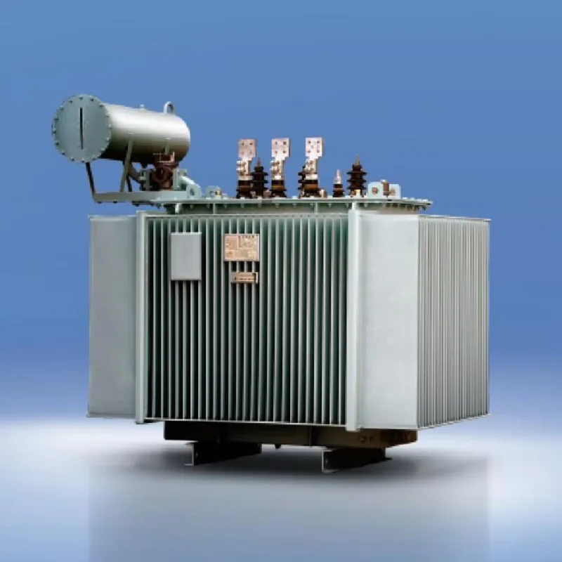
நிஜ உலக உதாரணம்: உங்கள் வீட்டிற்கு வெளியே உள்ள மின் கம்பத்தில் உள்ள உருளை வடிவ மின்மாற்றி முதன்மை மின்மாற்றியில் (7,200V விநியோகக் கோட்டுடன் இணைக்கப்பட்டுள்ளது) 7,200 திருப்பங்களையும், இரண்டாம் நிலை மின்மாற்றியில் (உங்கள் வீட்டிற்கு 240V வழங்கும்) 240 திருப்பங்களையும் மட்டுமே கொண்டிருக்கலாம்.
கணிதம் எளிமைப்படுத்தப்பட்டது
திருப்பங்களுக்கும் மின்னழுத்தத்திற்கும் இடையிலான உறவு மிகவும் எளிமையானது:
மின்னழுத்த விகிதம் = திருப்ப விகிதம்
இரண்டாம் நிலை மின்சுற்று முதன்மை மின்சுற்றை விட இரண்டு மடங்கு திருப்பங்களைக் கொண்டிருந்தால், வெளியீட்டு மின்னழுத்தம் உள்ளீட்டு மின்னழுத்தத்தை விட இரண்டு மடங்கு அதிகமாக இருக்கும். இரண்டாம் நிலை மின்சுற்று பாதி திருப்பங்களைக் கொண்டிருந்தால், வெளியீட்டு மின்னழுத்தம் உள்ளீட்டு மின்னழுத்தத்தில் பாதியாக இருக்கும்.
ஆனால் இங்கே பரிமாற்றம் உள்ளது: மின்னழுத்தம் அதிகரிக்கும் போது, மின்னோட்டம் விகிதாசாரமாகக் குறைகிறது. மின்னழுத்தம் குறையும் போது, மின்னோட்டம் அதிகரிக்கும். இது ஆற்றல் பாதுகாப்பைப் பராமரிக்கிறது - மின்மாற்றிகள் ஒன்றுமில்லாமல் சக்தியை உருவாக்க முடியாது.
சூத்திரம்: முதன்மை மின்னழுத்தம் ÷ இரண்டாம் நிலை மின்னழுத்தம் = முதன்மை திருப்பங்கள் ÷ இரண்டாம் நிலை திருப்பங்கள்
இந்த நேர்த்தியான எளிமை, ஒரு நூற்றாண்டுக்கும் மேலாக மின்மாற்றிகளை மின் விநியோகத்தின் முதுகெலும்பாக மாற்றியுள்ளது.
மின்மாற்றி கட்டுமானம்: வடிவமைப்பு ஏன் முக்கியமானது
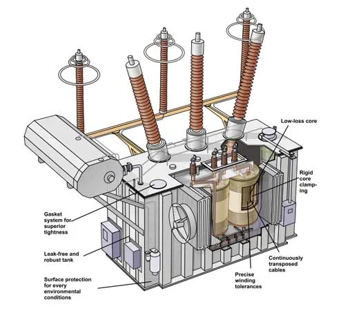
புரிதல் மின்சார மின்மாற்றிகள் எவ்வாறு செயல்படுகின்றன அவற்றை மிகவும் திறமையாகவும் நம்பகமானதாகவும் மாற்றும் புத்திசாலித்தனமான பொறியியலைப் பாராட்ட வேண்டும். மின்மாற்றி கட்டுமானத்தின் ஒவ்வொரு அம்சமும் இழப்புகளைக் குறைக்கும் அதே வேளையில் ஆற்றல் பரிமாற்றத்தை அதிகரிக்க உகந்ததாக்கப்பட்டுள்ளது.
இரும்பு மையக்கரு: காந்த சூப்பர்ஹைவே
மின்மாற்றி மையமானது திறமையான ஆற்றல் பரிமாற்றத்தை சாத்தியமாக்கும் முக்கியமான கூறு ஆகும். வடிவமைப்பு ஏன் முக்கியமானது என்பது இங்கே:
ஏன் இரும்பு? இரும்பு ஒரு ஃபெரோ காந்தத்தன்மை கொண்டது, அதாவது இது காற்றை விட ஆயிரக்கணக்கான மடங்கு சிறப்பாக காந்தப்புலங்களை குவிக்க முடியும். இந்த உயர் காந்த ஊடுருவு திறன் காந்தப் பாய்ச்சலுக்கான குறைந்த எதிர்ப்பு பாதையை உருவாக்குகிறது, இது மின்மாற்றி செயல்திறனை வியத்தகு முறையில் மேம்படுத்துகிறது.
லேமினேட் vs. சாலிட் கோர்: ஆரம்பகால மின்மாற்றிகள் திட இரும்பு மையங்களைப் பயன்படுத்தின, ஆனால் பொறியாளர்கள் விரைவாக ஒரு பெரிய சிக்கலைக் கண்டுபிடித்தனர்: சுழல் மின்னோட்டங்கள். திட கடத்திகள் மாறிவரும் காந்தப்புலங்களுக்கு ஆளாகும்போது, பொருளுக்குள் வட்ட மின்னோட்டங்கள் உருவாகின்றன, வெப்பத்தை உருவாக்கி ஆற்றலை வீணாக்குகின்றன.
தீர்வு? லேமினேட் செய்யப்பட்ட கோர்கள் சிலிக்கான் எஃகு மெல்லிய தாள்களால் (0.25-0.5 மிமீ தடிமன்) தயாரிக்கப்பட்டது, ஒவ்வொன்றும் அதன் அண்டை நாடுகளிலிருந்து மெல்லிய ஆக்சைடு பூச்சு அல்லது வார்னிஷ் மூலம் காப்பிடப்பட்டுள்ளன. இந்த லேமினேஷன்கள்:
- சுழல் மின்னோட்ட உருவாக்கத்தை வியத்தகு முறையில் குறைக்கிறது
- மைய வெப்பமாக்கல் மற்றும் ஆற்றல் இழப்பைக் குறைத்தல்
- ஒட்டுமொத்த மின்மாற்றி செயல்திறனை 95-99% ஆக மேம்படுத்தவும்
- சிறந்த வெப்பச் சிதறலை அனுமதிக்கவும்
சிலிக்கான் ஸ்டீல்: நவீன மின்மாற்றி கோர்கள் தூய இரும்பிற்கு பதிலாக சிலிக்கான் எஃகு பயன்படுத்துகின்றன. சிலிக்கான் மின் எதிர்ப்பை அதிகரிக்கிறது, சிறந்த காந்த பண்புகளை பராமரிக்கும் அதே வேளையில் சுழல் மின்னோட்டங்களை மேலும் குறைக்கிறது.
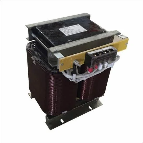
முறுக்கு நுட்பங்கள் மற்றும் பொருட்கள்
செப்பு கம்பி நன்மைகள்: மின்மாற்றி முறுக்குகள் செம்பு கம்பியைப் பயன்படுத்துகின்றன, ஏனெனில் தாமிரம் மின் கடத்துத்திறன், வெப்ப பண்புகள் மற்றும் செலவு ஆகியவற்றின் சிறந்த கலவையை வழங்குகிறது. சில பெரிய மின்மாற்றிகள் செலவு சேமிப்புக்காக அலுமினிய கம்பியைப் பயன்படுத்துகின்றன, ஆனால் தாமிரம் பிரீமியம் தேர்வாகவே உள்ளது.
காப்பு முக்கியத்துவம்: ஷார்ட் சர்க்யூட்களைத் தடுக்க, முறுக்குகளின் ஒவ்வொரு அடுக்கையும் சரியாக காப்பிட வேண்டும். நவீன மின்மாற்றிகள் அதிநவீன காப்பு அமைப்புகளைப் பயன்படுத்துகின்றன, அவற்றுள்:
- தனிப்பட்ட கம்பிகளில் பற்சிப்பி பூச்சு
- அடுக்குகளுக்கு இடையில் காகிதம் அல்லது பாலிமர் காப்பு
- பெரிய மின்மாற்றிகளில் எண்ணெய் அல்லது எரிவாயு காப்பு
வெப்ப மேலாண்மை: மின்மாற்றிகள் செயல்பாட்டின் போது வெப்பத்தை உருவாக்குகின்றன, முதன்மையாக முறுக்குகளில் உள்ள எதிர்ப்பு மற்றும் மையத்தில் உள்ள காந்த இழப்புகள் மூலம். பயனுள்ள குளிரூட்டும் அமைப்புகள் - எளிய காற்று சுழற்சி முதல் சிக்கலான எண்ணெய் குளிரூட்டும் அமைப்புகள் வரை - நம்பகமான செயல்பாட்டிற்கு அவசியம்.
முக்கிய வகைகள் மற்றும் வடிவங்கள்
EI லேமினேஷன்கள்: மிகவும் பொதுவான மின்மாற்றி கட்டுமானம் E-வடிவ மற்றும் I-வடிவ லேமினேஷன்களை மாறி மாறி அடுக்கி வைக்கிறது. E துண்டுகள் பிரதான உடலை உருவாக்குகின்றன, அதே நேரத்தில் I துண்டுகள் காந்த சுற்றுகளை மூடுகின்றன. இந்த வடிவமைப்பு சிறந்த காந்த இணைப்பை வழங்குகிறது, அதே நேரத்தில் எளிதான அசெம்பிளியை அனுமதிக்கிறது.
டொராய்டல் கோர்கள்: வளைய வடிவ (டொராய்டல்) மையங்கள் பல நன்மைகளை வழங்குகின்றன:
- குறைந்தபட்ச காந்தப் பாய்வு கசிவு
- சிறிய, திறமையான வடிவமைப்பு
- அமைதியான செயல்பாடு
- குறைந்த மின்காந்த குறுக்கீடு
ஷெல் vs. கோர் வகை:
- மைய வகை: மையக் கால்களைச் சுற்றி சுற்றப்பட்ட முறுக்குகள் (விநியோக மின்மாற்றிகளுக்கு மிகவும் பொதுவானது)
- ஷெல் வகை: கோர் முறுக்குகளைச் சுற்றி உள்ளது (அதிக சக்தி பயன்பாடுகளுக்கு விரும்பப்படுகிறது)
ஒவ்வொரு வடிவமைப்பும் பயன்பாடு, மின்னழுத்த நிலை மற்றும் மின் தேவைகளைப் பொறுத்து குறிப்பிட்ட நன்மைகளைக் கொண்டுள்ளது.
மின்மாற்றிகளின் வகைகள் மற்றும் அவற்றின் பயன்பாடுகள்
கொள்கை மின்சார மின்மாற்றிகள் எவ்வாறு செயல்படுகின்றன பல்வேறு வகையான மின்மாற்றிகளுக்குப் பொருந்தும், ஒவ்வொன்றும் குறிப்பிட்ட பயன்பாடுகளுக்கு உகந்ததாக்கப்பட்டுள்ளது.
சக்தி மின்மாற்றிகள்
மின்மாற்றிகள் மின் கட்டத்தில் மொத்த மின் ஆற்றல் பரிமாற்றத்தைக் கையாளவும்:
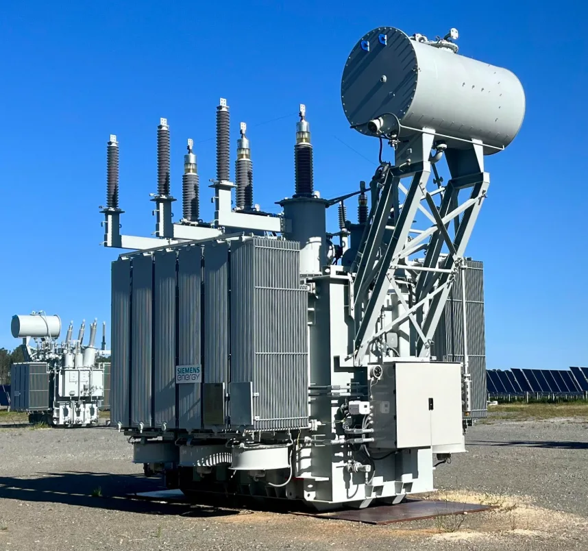
டிரான்ஸ்மிஷன் டிரான்ஸ்ஃபார்மர்கள்: திறமையான நீண்ட தூர போக்குவரத்திற்காக மின் நிலைய வெளியீட்டை உயர் பரிமாற்ற மின்னழுத்தங்களுக்கு (115kV முதல் 765kV வரை) அதிகரிக்கவும். இந்த மிகப்பெரிய அலகுகள் நூற்றுக்கணக்கான டன் எடையும் நூற்றுக்கணக்கான மெகாவாட்களைக் கையாளக்கூடியவை.
விநியோக மின்மாற்றிகள்: சுற்றுப்புறங்கள் மற்றும் கட்டிடங்களுக்கு மின்னழுத்தத்தைக் குறைக்கும் பழக்கமான உருளை அல்லது திண்டு-ஏற்றப்பட்ட மின்மாற்றிகள். மின் கட்டத்தின் இந்த வேலைக்காரர்கள் நடுத்தர மின்னழுத்த விநியோகக் கோடுகளை (பொதுவாக 4kV-35kV) பயன்படுத்தக்கூடிய மின்னழுத்தங்களாக (120V-480V) மாற்றுகிறார்கள்.
துணை மின்நிலைய மின்மாற்றிகள்: பெரிய மின்மாற்றிகள், பரிமாற்றம் மற்றும் விநியோக அமைப்புகளுக்கு இடையில் இடைமுகமாக செயல்படுகின்றன, பெரும்பாலும் பரிமாற்ற மின்னழுத்த நிலைகளிலிருந்து விநியோக நிலைகளுக்குக் கீழே செல்கின்றன.
தனிமைப்படுத்தும் மின்மாற்றிகள்
தனிமைப்படுத்தும் மின்மாற்றிகள் மின்னழுத்த அளவுகள் அப்படியே இருந்தாலும், உள்ளீடு மற்றும் வெளியீட்டு சுற்றுகளுக்கு இடையேயான நேரடி இணைப்பை நீக்குவதன் மூலம் மின் பாதுகாப்பை வழங்குதல்:
மருத்துவ உபகரணங்கள்: மருத்துவமனைகள், நோயாளிகளை மின் அதிர்ச்சியிலிருந்து பாதுகாக்க தனிமைப்படுத்தும் மின்மாற்றிகளைப் பயன்படுத்துகின்றன, குறிப்பாக மருத்துவ சாதனங்கள் நோயாளிகளை நேரடியாகத் தொடர்பு கொள்ளும் பகுதிகளில்.
உணர்திறன் மின்னணுவியல்: ஆய்வகம் மற்றும் சோதனை உபகரணங்களுக்கு பெரும்பாலும் மின் மூலத்திலிருந்து தரை சுழல்கள் மற்றும் மின் சத்தத்தை அகற்ற தனிமைப்படுத்தும் மின்மாற்றிகள் தேவைப்படுகின்றன.
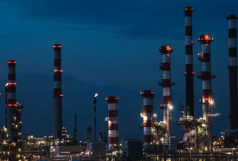
பாதுகாப்பு பயன்பாடுகள்: தொழில்துறை சூழல்கள் தொழிலாளர்களையும் உபகரணங்களையும் ஆபத்தான தரைப் பிழைகளிலிருந்து பாதுகாக்க தனிமைப்படுத்தும் மின்மாற்றிகளைப் பயன்படுத்துகின்றன.
கருவி மின்மாற்றிகள்
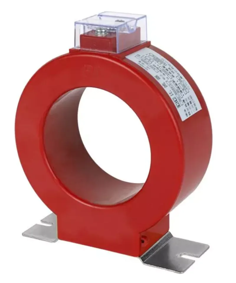
மின்னோட்ட மின்மாற்றிகள் (CTகள்): பாதுகாப்பு ரிலேக்கள் மற்றும் அளவீட்டு கருவிகளுக்கு அதிக மின்னோட்டங்களை பாதுகாப்பான, அளவிடக்கூடிய நிலைகளுக்குக் குறைக்கவும். இவை ஆபத்தான உயர் மின்னோட்டங்களை நேரடியாகக் கையாளாமல் பவர் கிரிட் கண்காணிப்பை அனுமதிக்கின்றன.
மின்னழுத்த மின்மாற்றிகள் (VTகள்): அளவீடு மற்றும் பாதுகாப்பு அமைப்புகளுக்கு உயர் மின்னழுத்தங்களை பாதுகாப்பான நிலைகளுக்குக் குறைக்கவும். மின் கட்ட நிலைமைகளைக் கண்காணிப்பதற்கு அவசியம்.
ஒருங்கிணைந்த கருவி மின்மாற்றிகள்: சில பயன்பாடுகள் ஒற்றை அலகில் மின்னோட்டம் மற்றும் மின்னழுத்த மாற்றம் இரண்டையும் வழங்கும் மின்மாற்றிகளைப் பயன்படுத்துகின்றன.
சிறப்பு மின்மாற்றிகள்
ஆடியோ டிரான்ஸ்ஃபார்மர்கள்: ஆடியோ அதிர்வெண் பதிலுக்காக உகந்ததாக்கப்பட்ட இந்த மின்மாற்றிகள், உயர்தர ஆடியோ உபகரணங்களில் மின்மறுப்பு பொருத்தத்தையும் தனிமைப்படுத்தலையும் வழங்குகின்றன.
பல்ஸ் டிரான்ஸ்ஃபார்மர்கள்: விரைவான மின்னழுத்த மாற்றங்களைக் கையாள வடிவமைக்கப்பட்ட இவை, டிஜிட்டல் எலக்ட்ரானிக்ஸ் மற்றும் ஸ்விட்சிங் பவர் சப்ளைகளில் அவசியம்.
தானியங்கி மின்மாற்றிகள்: இரண்டு-சுருட்டு வகைகளை விட மிகவும் கச்சிதமான மற்றும் திறமையான ஒற்றை-சுருட்டு மின்மாற்றிகள், பொதுவாக மின்னழுத்த சீராக்கிகள் மற்றும் மாறி மின்னழுத்த விநியோகங்களில் பயன்படுத்தப்படுகின்றன.
பொதுவான மின்மாற்றி சிக்கல்கள் மற்றும் தீர்வுகள்
புரிதல் மின்சார மின்மாற்றிகள் எவ்வாறு செயல்படுகின்றன அவை சரியாக வேலை செய்யாதபோது அதை அங்கீகரிப்பதும் இதன் பொருள். மிகவும் பொதுவான சிக்கல்கள் இங்கே:
அதிக வெப்பமூட்டும் சிக்கல்கள்
அறிகுறிகள்: சூடான மின்மாற்றி மேற்பரப்புகள், எரியும் வாசனை, பெரிய மின்மாற்றிகளில் எண்ணெய் கசிவுகள்.
காரணங்கள்: அதிக சுமை, மோசமான காற்றோட்டம், காப்பு முறிவு, அதிகப்படியான சுற்றுப்புற வெப்பநிலை
தீர்வுகள்: சுமை குறைப்பு, மேம்படுத்தப்பட்ட குளிர்ச்சி, தொழில்முறை ஆய்வு மற்றும் பராமரிப்பு
மைய செறிவு
அறிகுறிகள்: அதிகப்படியான வெப்பமாக்கல், சிதைந்த வெளியீட்டு அலைவடிவங்கள், உரத்த ஹம்மிங் அல்லது சலசலப்பு
காரணங்கள்: அதிக மின்னழுத்த நிலைமைகள், ஏசி விநியோகத்தில் டிசி கூறு, தவறான மின்மாற்றி அளவு.
தீர்வுகள்: மின்னழுத்த ஒழுங்குமுறை, DC தடுப்பு, சரியான அளவிலான மின்மாற்றி தேர்வு
காப்பு முறிவு
அறிகுறிகள்: மின் வளைவு, தரைப் பிழைகள், குறைக்கப்பட்ட காப்பு எதிர்ப்பு
காரணங்கள்: வயது, ஈரப்பதம் உட்செலுத்துதல், வெப்ப அழுத்தம், மின் அழுத்தம்
தீர்வுகள்: தொழில்முறை சோதனை, ஈரப்பதம் நீக்கம், காப்பு மாற்று அல்லது மின்மாற்றி மாற்று
பராமரிப்பு குறிப்புகள்
- காட்சி ஆய்வு: உடல் சேதம், எண்ணெய் கசிவுகள், அதிக வெப்பமடைதல் அறிகுறிகளுக்கான வழக்கமான சோதனைகள்.
- மின் சோதனை: முக்கியமான பயன்பாடுகளுக்கான வருடாந்திர காப்பு எதிர்ப்பு மற்றும் திருப்ப விகித சோதனை.
- வெப்பநிலை கண்காணிப்பு: சரியான குளிர்ச்சி மற்றும் காற்றோட்டத்தை உறுதி செய்தல்
- சுமை கண்காணிப்பு: மின்மாற்றி ஆயுளைக் குறைக்கும் நாள்பட்ட ஓவர்லோடிங்கைத் தடுத்தல்

நீங்கள் ஒவ்வொரு நாளும் பயன்படுத்தும் நிஜ உலக பயன்பாடுகள்
கொள்கை மின்சார மின்மாற்றிகள் எவ்வாறு செயல்படுகின்றன நவீன வாழ்க்கையின் கிட்டத்தட்ட ஒவ்வொரு அம்சத்தையும் தொடுகிறது:
தொலைபேசி மற்றும் மடிக்கணினி சார்ஜர்கள்: இந்த சிறிய மாறுதல் மின் விநியோகங்கள், உங்கள் சாதனங்களுக்குத் தேவையான DC மின்னழுத்தங்களுக்கு AC சுவர் சக்தியை திறமையாக மாற்ற உயர் அதிர்வெண் மின்மாற்றிகளைப் பயன்படுத்துகின்றன. அதிக அதிர்வெண் பாரம்பரிய 60Hz வடிவமைப்புகளை விட மிகச் சிறிய, இலகுவான மின்மாற்றிகளை அனுமதிக்கிறது.
மைக்ரோவேவ் ஓவன்கள்: வீட்டு 120V ஐ மைக்ரோவேவ்களை உருவாக்கும் மேக்னட்ரானுக்குத் தேவையான 2,000-4,000V ஆக மாற்ற உயர் மின்னழுத்த மின்மாற்றிகளைப் பயன்படுத்தவும். இந்த மின்மாற்றிகள் மைக்ரோவேவ் உற்பத்தியின் உயர் மின்னழுத்த, உயர் மின்னோட்ட தேவைகளைக் கையாள குறிப்பாக வடிவமைக்கப்பட்டுள்ளன.
கார் பற்றவைப்பு அமைப்புகள்: நவீன வாகனங்கள் காரின் 12V பேட்டரி சக்தியை தீப்பொறி பிளக்குகளின் மின் வளைவுகளை உருவாக்கத் தேவையான 10,000-50,000V ஆக மாற்ற பற்றவைப்பு மின்மாற்றிகளை (பற்றவைப்பு சுருள்கள்) பயன்படுத்துகின்றன.
மின் கட்டமைப்பு: நீங்கள் ஒவ்வொரு முறை ஒரு லைட் சுவிட்சை புரட்டும்போதும், உங்கள் மின்சாரம் 4-6 வெவ்வேறு டிரான்ஸ்பார்மர்கள் வழியாகச் சென்றிருக்கலாம்:
- மின் நிலையத்தில் ஸ்டெப்-அப் மின்மாற்றி
- டிரான்ஸ்மிஷன் துணை மின்நிலைய மின்மாற்றிகள்
- விநியோக துணை மின்நிலைய மின்மாற்றிகள்
- சுற்றுப்புற விநியோக மின்மாற்றி
- பெரிய வசதிகளுக்கான கட்டிட-குறிப்பிட்ட மின்மாற்றிகள் இருக்கலாம்
ஆடியோ உபகரணங்கள்: உயர்நிலை ஆடியோ அமைப்புகள் மின்மறுப்பு பொருத்தம், இரைச்சல் தனிமைப்படுத்தல் மற்றும் சமிக்ஞை இணைப்புக்கு மின்மாற்றிகளைப் பயன்படுத்துகின்றன. இந்த ஆடியோ மின்மாற்றிகள் முழு கேட்கக்கூடிய அதிர்வெண் வரம்பிலும் ஒலி தரத்தைப் பாதுகாக்க சிறப்பாக வடிவமைக்கப்பட்டுள்ளன.
வெல்டிங் உபகரணங்கள்: ஆர்க் வெல்டர்கள் நிலையான மின்சார விநியோகத்தை வெல்டிங்கிற்குத் தேவையான உயர்-மின்னோட்ட, கட்டுப்படுத்தப்பட்ட-மின்னழுத்த வெளியீட்டிற்கு மாற்ற மின்மாற்றிகளைப் பயன்படுத்துகின்றனர். இந்த வலுவான மின்மாற்றிகள் தீவிர மின் மற்றும் வெப்ப அழுத்தத்தைக் கையாள வேண்டும்.
மின்மாற்றிகளில் ஆற்றல் திறன் மற்றும் இழப்புகள்
நவீன மின்சார மின்மாற்றிகள் வேலை செய்கின்றன குறிப்பிடத்தக்க செயல்திறனுடன் - பொதுவாக 95-99% - ஆனால் சிறிய இழப்புகளைப் புரிந்துகொள்வது அவற்றின் அதிநவீன வடிவமைப்பைப் பாராட்ட உதவுகிறது.
மின்மாற்றி இழப்புகளின் வகைகள்
செப்பு இழப்புகள் (I²R இழப்புகள்): முறுக்குகளில் மின் எதிர்ப்பால் உருவாகும் வெப்பம். இந்த இழப்புகள் மின்னோட்ட சுமையுடன் அதிகரிக்கின்றன மற்றும் பெரிய கடத்திகள் மற்றும் உகந்த முறுக்கு வடிவமைப்பைப் பயன்படுத்துவதன் மூலம் குறைக்கப்படலாம்.
இரும்பு மைய இழப்புகள்: காந்த மையப் பொருளில் இழக்கப்படும் ஆற்றல், பின்வருவனவற்றைக் கொண்டுள்ளது:
- ஹிஸ்டெரெசிஸ் இழப்புகள்: மையத்தை மீண்டும் மீண்டும் காந்தமாக்கவும் காந்த நீக்கவும் தேவையான ஆற்றல்
- எடி மின்னோட்ட இழப்புகள்: மையப் பொருளில் தூண்டப்படும் வட்ட மின்னோட்டங்கள் (லேமினேஷன்களால் குறைக்கப்படுகின்றன)
தவறான இழப்புகள்: மின் பரிமாற்றத்திற்கு பங்களிக்காத மின்காந்த புலங்களுக்கு ஆற்றல் இழக்கப்படுகிறது. கவனமாக வடிவமைக்கப்பட்ட வடிவமைப்பு சரியான காந்தக் கவசம் மற்றும் முறுக்கு உள்ளமைவு மூலம் இவற்றைக் குறைக்கிறது.
செயல்திறன் மேம்பாடுகள்
நவீன மின்மாற்றி வடிவமைப்பு பல செயல்திறன் மேம்பாடுகளை உள்ளடக்கியது:
- உருவமற்ற எஃகு கருக்கள்: குறைந்த மைய இழப்புகளைக் கொண்ட புதிய காந்தப் பொருட்கள்
- உகந்த முறுக்கு வடிவமைப்புகள்: கணினியால் வடிவமைக்கப்பட்ட கடத்தி அமைப்பு, எதிர்ப்பு மற்றும் தவறான இழப்புகளைக் குறைக்கிறது.
- மேம்பட்ட குளிரூட்டும் அமைப்புகள்: சிறந்த வெப்ப நீக்கம் அதிக சக்தி அடர்த்தி மற்றும் செயல்திறனை அனுமதிக்கிறது.
- டேப் சேஞ்சர்களை ஏற்று: மாறுபட்ட சுமை நிலைகளில் உகந்த செயல்திறனைப் பராமரிக்கும் தானியங்கி மின்னழுத்த ஒழுங்குமுறை அமைப்புகள்.
ஆற்றல் சேமிப்பு நன்மைகள்
உயர் திறன் கொண்ட மின்மாற்றிகள் மின் கட்டம் முழுவதும் பயன்படுத்தப்படும்போது மகத்தான ஆற்றல் சேமிப்பை வழங்குகின்றன. விநியோக மின்மாற்றிகளில் 1% செயல்திறன் மேம்பாடு, ஒரு பெரிய மின் கட்டத்தில் ஆண்டுதோறும் பில்லியன் கணக்கான கிலோவாட்-மணிநேரங்களை மிச்சப்படுத்துகிறது - இது லட்சக்கணக்கான வீடுகளுக்கு மின்சாரம் வழங்க போதுமானது.
மேம்பட்ட கருத்துக்கள்: அடிப்படைகளுக்கு அப்பால்
ஆழமாகப் புரிந்துகொள்ள ஆர்வமுள்ளவர்களுக்கு மின்சார மின்மாற்றிகள் எவ்வாறு செயல்படுகின்றன, பல மேம்பட்ட கருத்துக்கள் அடிப்படைக் கொள்கைகளை விரிவுபடுத்துகின்றன:
மூன்று-கட்ட மின்மாற்றிகள்
பெரும்பாலான மின் கட்டமைப்பு பயன்பாடுகள் மிகவும் திறமையான மின் பரிமாற்றத்திற்காக மூன்று-கட்ட மின்சாரத்தைப் பயன்படுத்துகின்றன. மூன்று-கட்ட மின்மாற்றிகள் மூன்று தனித்தனி ஒற்றை-கட்ட மின்மாற்றிகளைப் பயன்படுத்துகின்றன அல்லது ஒரு பொதுவான மையத்தில் மூன்று செட் முறுக்குகளைக் கொண்ட ஒற்றை மூன்று-கட்ட அலகு பயன்படுத்துகின்றன.
மூன்று-கட்ட அமைப்புகளின் நன்மைகள்:
- மிகவும் திறமையான மின் பரிமாற்றம்
- சீரான மின் விநியோகம்
- சிறந்த மோட்டார் செயல்திறன்
- குறைக்கப்பட்ட கடத்தி தேவைகள்
தானியங்கி மின்மாற்றிகள்
தானியங்கி மின்மாற்றிகள் ஒற்றை முறுக்கு முறையைப் பயன்படுத்துகின்றன, இது முதன்மை மற்றும் இரண்டாம் நிலை இரண்டாகவும் செயல்படுகிறது, முறுக்குடன் வெவ்வேறு புள்ளிகளில் மின் இணைப்புகளைக் கொண்டுள்ளது. இந்த வடிவமைப்பு தனித்தனி முறுக்கு மின்மாற்றிகளை விட மிகவும் கச்சிதமானது மற்றும் திறமையானது, ஆனால் மின் தனிமைப்படுத்தலை வழங்காது.
பயன்பாடுகள்: மின்னழுத்த சீராக்கிகள், மோட்டார் ஸ்டார்ட்டர்கள், மூன்று-கட்டத்திலிருந்து இரண்டு-கட்ட மாற்றம்
மாறி மின்மாற்றிகள்
மாறி மின்மாற்றிகள் (Variac® அலகுகள் போன்றவை) மின்மாற்றி முறுக்கு இணைப்புப் புள்ளியை மாற்றுவதன் மூலம் தொடர்ச்சியான மின்னழுத்த சரிசெய்தலை அனுமதிக்கின்றன. துல்லியமான மின்னழுத்தக் கட்டுப்பாடு தேவைப்படும் உபகரணங்கள் மற்றும் பயன்பாடுகளைச் சோதிக்க இவை அவசியம்.
உயர் அதிர்வெண் மின்மாற்றிகள்
நவீன மின்னணு சாதனங்கள் அதிக அதிர்வெண் மின்மாற்றிகளைப் பயன்படுத்துகின்றன (60Hz ஐ விட ஆயிரக்கணக்கான அல்லது மில்லியன் ஹெர்ட்ஸில் இயங்குகின்றன). அதிக அதிர்வெண்கள் மிகச் சிறிய மின்மாற்றி கோர்களையும் மின் விநியோகங்களை மாற்றுவதில் மேம்பட்ட செயல்திறனையும் அனுமதிக்கின்றன.
பயன்பாடுகள்: கணினி மின் விநியோகங்கள், LED இயக்கிகள், வயர்லெஸ் சார்ஜிங் அமைப்புகள், மின் இன்வெர்ட்டர்கள்
அடிக்கடி கேட்கப்படும் கேள்விகள்
நிறுவல் மற்றும் தொழில்நுட்ப கேள்விகள்
கேள்வி: மின்மாற்றிகளில் H மற்றும் X முனையங்கள் குறிக்கப்பட்டால் என்ன அர்த்தம்?
A: H முனையங்கள் உயர் மின்னழுத்த இணைப்புகளைக் குறிக்கின்றன, X முனையங்கள் குறைந்த மின்னழுத்த இணைப்புகளைக் குறிக்கின்றன. H முனையங்கள் எப்போதும் முதன்மையானவை மற்றும் X முனையங்கள் இரண்டாம் நிலை என்பது ஒரு பொதுவான தவறான கருத்து - இது படி-கீழ் மின்மாற்றிகளுக்கு உண்மை, ஆனால் படி-மேல் மின்மாற்றிகளில் இணைப்புகள் தலைகீழாக மாற்றப்பட வேண்டும்.
கேள்வி: ஒற்றை-கட்ட மின்மாற்றியை மூன்று-கட்ட மின்சக்தியாக மாற்ற முடியுமா?
ப: இல்லை. ஒற்றை கட்ட மின்சாரத்தை மூன்று கட்டங்களாக மாற்ற, கட்ட மாற்றிகள் அல்லது உலைகள் மற்றும் மின்தேக்கிகள் போன்ற கட்ட மாற்றும் சாதனங்கள் தேவை. உங்களுக்கு மூன்று தனித்தனி ஒற்றை-கட்ட மின்மாற்றிகள் அல்லது ஒரு நோக்கத்திற்காக உருவாக்கப்பட்ட மூன்று-கட்ட மின்மாற்றி தேவை.
கேள்வி: மின்மாற்றிகளில் அதிக சத்தம் அல்லது அசாதாரண சத்தங்கள் ஏற்படுவதற்கு என்ன காரணம்?
A: மின்மாற்றி சத்தம் காந்த சுருக்கத்தால் ஏற்படுகிறது, இது காந்தமாக்கப்பட்ட போது காந்தத் தாள் எஃகு நீட்டிக்கப்படுவதற்கும், காந்தமாக்கப்பட்ட போது சுருங்குவதற்கும் காரணமாகிறது. ஒவ்வொரு AC சுழற்சியிலும் கோர் ஷீட்களில் நீட்டிப்புகள் மற்றும் சுருக்கங்கள் ஒழுங்கற்ற முறையில் நிகழ்கின்றன, இதனால் அதிர்வு மற்றும் சத்தம் உருவாகிறது. அதிகப்படியான சத்தம் தளர்வான கூறுகள், ஓவர்லோடிங் அல்லது தொழில்முறை ஆய்வு தேவைப்படும் கோர் சிக்கல்களைக் குறிக்கலாம்.
கேள்வி: 1kVA க்கும் அதிகமான மின்மாற்றிகளை ஏன் எளிதாக மீண்டும் ஊட்ட முடியாது (தலைகீழ் பயன்பாட்டில்)?
A: பெரிய மின்மாற்றிகளை பின்புறமாக செலுத்துவதால், மின்மாற்றி மின்சக்தியில் அதிக உந்துவிசை மின்னோட்டம் ஏற்படும், மேலும் சர்க்யூட் பிரேக்கர்கள் மற்றும் உருகிகள் செயலிழந்து போகும். இந்தப் பிரச்சினையை கணிப்பது கடினம், அதை சரிசெய்வது விலை உயர்ந்தது. தலைகீழ் பயன்பாடுகளுக்கு ஸ்டெப்-அப் யூனிட்டுகளாக குறிப்பாக வளைக்கப்பட்ட மின்மாற்றிகளை வாங்குவது நல்லது.
டிரான்ஸ்ஃபார்மர் எண்ணெய் மற்றும் பராமரிப்பு
கே: மின்மாற்றிகள் பொதுவாக எவ்வளவு காலம் நீடிக்கும்?
A: ஒரு பொதுவான மின்மாற்றியின் ஆயுட்காலம், கூறுகளின் தரம் முதல் பராமரிப்பு நடைமுறைகள் வரை, நிலைமைகளைப் பொறுத்து 20 முதல் 40 ஆண்டுகள் வரை இருக்கலாம். சில மின்மாற்றிகள் பல தசாப்தங்களாக பெரிய பிரச்சினைகள் இல்லாமல் சேவை செய்கின்றன, மற்றவை சுற்றுச்சூழல் காரணிகள் அல்லது மோசமான பராமரிப்பு காரணமாக முன்கூட்டியே தேய்மானத்தை அனுபவிக்கின்றன.
கே: மின்மாற்றியின் ஆயுளைக் குறைக்கும் முக்கிய காரணிகள் யாவை?
A: மின்மாற்றியின் ஆயுட்காலத்தை நிர்ணயிக்கும் மூன்று கூறுகள் வெப்பம், ஈரப்பதம் மற்றும் ஆக்ஸிஜன் ஆகும். இயக்க வெப்பநிலையில் ஒவ்வொரு 10°C அதிகரிப்புக்கும், செல்லுலோஸ் காகிதத்தைத் தாக்கும் ஆக்சிஜனேற்ற துணைப் பொருட்கள் இரட்டிப்பாகின்றன. சரியான குளிர்ச்சி மற்றும் அதிக சுமையைத் தவிர்ப்பது நீண்ட ஆயுளுக்கு அவசியம்.
கே: டிரான்ஸ்பார்மர் ஆயிலை எத்தனை முறை சோதிக்க வேண்டும்?
A: சிக்கல்களைக் கண்டறியவும், சாத்தியமான சிக்கல்களைக் கண்டறியவும், தோல்விகளைத் தடுக்கவும் முக்கியமான தரவை வழங்க மின்கடத்தா திரவ மாதிரிகளை ஆண்டுதோறும் சோதிக்க SDMyers பரிந்துரைக்கிறது. 2023 ஆம் ஆண்டில் NFPA 70B இன் தரப்படுத்தல் என்பது மின்மாற்றி பராமரிப்புக்கான வருடாந்திர திரவ மாதிரி மற்றும் சோதனை இப்போது குறைந்தபட்சத் தேவையாகும். முக்கியமான உபகரணங்களுக்கு அடிக்கடி சோதனை தேவைப்படலாம்.
கேள்வி: எண்ணெய் மாதிரிகளை சேகரிக்கும் போது என்ன சுற்றுச்சூழல் நிலைமைகளைத் தவிர்க்க வேண்டும்?
A: குளிர் நிலைகள் அல்லது ஈரப்பதம் 70 சதவீதத்திற்கும் அதிகமாக இருக்கும் சூழ்நிலைகள் தவிர்க்கப்பட வேண்டும், ஏனெனில் இது மாதிரியில் ஈரப்பதத்தை அதிகரிக்கும். சிறந்த சூழ்நிலை 95°F (35°C) அல்லது அதற்கு மேல், பூஜ்ஜிய சதவீத ஈரப்பதம் மற்றும் காற்று இல்லாமல் இருப்பது.
கே: டிரான்ஸ்பார்மர் எண்ணெய் உண்மையில் என்ன செய்கிறது?
A: மின்மாற்றி எண்ணெய் மூன்று முக்கிய செயல்பாடுகளைச் செய்கிறது: இது மின்கடத்தா கூறுகளுக்கு ஒரு சிறந்த மின்கடத்தா ஊடகம், முறுக்குகளிலிருந்து தொட்டி சுவர்கள் மற்றும் ரேடியேட்டர்களுக்கு வெப்பத்தைச் சிதறடிக்க ஒரு நல்ல வெப்பப் பரிமாற்றி, மேலும் இது மின்மாற்றி பயன்பாடுகளுக்கு இன்னும் மலிவான திரவமாகும்.
பாதுகாப்பு மற்றும் நிறுவல் சிக்கல்கள்
கேள்வி: ஒரு மின்மாற்றி இரண்டாம் நிலை சரியாக தரையிறக்கப்படாவிட்டால் என்ன நடக்கும்?
A: மின்மாற்றியின் இரண்டாம் நிலை சரியாக தரையிறக்கப்படாவிட்டால், வெளியீட்டு மின்னழுத்தம் கட்டங்களுக்கு இடையில் சரியாக இருக்கும், ஆனால் அது மிதக்கும் மற்றும் பூமியின் தரைக்கு குறிப்பிடப்படாது. இது பாதுகாப்பு அபாயங்களையும் அளவீட்டு சிக்கல்களையும் உருவாக்குகிறது.
கேள்வி: எல்லா மின்மாற்றிகளுக்கும் அதிர்வு பட்டைகள் தேவையா?
A: மையத்தில் உள்ள மின்காந்த புலம் காரணமாக அனைத்து மின்மாற்றிகளும் 120 ஹெர்ட்ஸில் அதிர்வுறும். இந்த அதிர்வுகளும் கேட்கக்கூடிய சத்தமும் தரை வழியாக பரவக்கூடும்; வணிக பயன்பாடுகளில் இந்த சிக்கலைக் குறைக்க அதிர்வு பட்டைகள் மற்றும் தனிமைப்படுத்திகள் உதவுகின்றன.
கேள்வி: ஹார்மோனிக் சிதைவால் மின்மாற்றிகள் அதிக வெப்பமடையுமா?
A: நேரியல் அல்லாத சுமைகள் மற்றும் அவை உருவாக்கும் ஹார்மோனிக்ஸ் பரவல் காரணமாக, மின்மாற்றிகள் சரியாக குறிப்பிடப்படாவிட்டால் அதிக வெப்பமடையக்கூடும். நவீன மின்னணு சுமைகள் ஹார்மோனிக்ஸ்களை உருவாக்குகின்றன, அவை பெயர்ப்பலகை மதிப்பீட்டைத் தாண்டி கூடுதல் வெப்பத்தை ஏற்படுத்தும்.
செயல்திறன் மற்றும் செயல்திறன்
கே: மின்மாற்றிகளில் மின்னழுத்த ஒழுங்குமுறை என்றால் என்ன?
A: மின்மாற்றிகளில் மின்னழுத்த ஒழுங்குமுறை என்பது முழு சுமை மின்னழுத்தத்திற்கும் சுமை இல்லாத மின்னழுத்தத்திற்கும் இடையிலான வித்தியாசமாகும், இது பொதுவாக சதவீதத்தின் அடிப்படையில் வெளிப்படுத்தப்படுகிறது. நல்ல ஒழுங்குமுறை என்பது வெளியீட்டு மின்னழுத்தம் மாறுபட்ட சுமை நிலைகளின் கீழ் நிலையாக இருப்பதைக் குறிக்கிறது.
கே: மின்மாற்றிகளில் வெப்பநிலை உயர்வு என்றால் என்ன?
A: ஒரு மின்மாற்றியில் வெப்பநிலை உயர்வு என்பது, ஏற்கனவே உள்ள சுற்றுப்புற வெப்பநிலையை விட, முறுக்குகள், எண்ணெய் மற்றும் காப்பு ஆகியவற்றின் சராசரி வெப்பநிலையாகும். இந்த விவரக்குறிப்பு, மின்மாற்றி சாதாரண செயல்பாட்டின் போது எவ்வளவு வெப்பத்தை உருவாக்குகிறது என்பதைக் குறிக்கிறது.
கேள்வி: முறையான பராமரிப்பு மின்மாற்றி செயலிழப்பு விகிதங்களை எவ்வளவு குறைக்கும்?
A: முறையான பராமரிப்பு 40% க்கும் அதிகமான தோல்வி விகிதங்களைக் குறைக்கலாம், உபகரணங்களின் ஆயுளை நீட்டிக்கலாம் மற்றும் பேரழிவு தரும் முறிவுகளைத் தடுக்கலாம். வழக்கமான பராமரிப்பு அவசரகால பழுதுபார்ப்பு அல்லது மாற்றீடுகளுடன் ஒப்பிடும்போது மிகப்பெரிய செலவு சேமிப்பை வழங்குகிறது.
சரிசெய்தல் மற்றும் கண்டறிதல்
கேள்வி: மின்மாற்றி வேலை செய்யாதபோது முதலில் எதைச் சரிபார்க்க வேண்டும்?
A: மின்மாற்றியை சக்தியூட்ட முடிந்தால், மின்னழுத்தம் சகிப்புத்தன்மைக்குள் இருப்பதை உறுதிசெய்ய, மின்மாற்றியில் சுமை இல்லாமல் வெளியீட்டு மின்னழுத்தத்தை அளவிடவும். சுமை பக்கத்தில் ஒரு நடுநிலை பெறப்பட்டால், தேசிய மின்சாரக் குறியீட்டின் தேவைகளுக்கு ஏற்ப நடுநிலை தரை பிணைப்பு நிறைவேற்றப்படுவதை உறுதிசெய்யவும்.
கே: மின்மாற்றி பிரச்சனைகளின் எச்சரிக்கை அறிகுறிகள் யாவை?
A: விசித்திரமான அல்லது உரத்த சத்தங்கள் பொதுவாக அதிர்வுகளால் ஏற்படுகின்றன, அங்கு கூறுகள் வழக்கத்தை விட அதிகமாக சத்தமிடுகின்றன, இது தளர்வான திருகுகள் அல்லது ஒருவேளை எண்ணெய் பற்றாக்குறையைக் குறிக்கிறது. புகை பொதுவாக வெளிப்படும் கம்பிகளால் ஏற்படுகிறது, இது தீப்பொறிகளை உருவாக்கி புகையை உருவாக்குகிறது.
கே: டிரான்ஸ்பார்மரின் ஆரோக்கியம் பற்றி கரைந்த வாயு பகுப்பாய்வு (DGA) உங்களுக்கு என்ன சொல்கிறது?
A: DGA சோதனையானது எண்ணெயில் கரைந்துள்ள அசிட்டிலீன், மீத்தேன், ஹைட்ரஜன், ஈத்தேன், எத்திலீன், ஆக்ஸிஜன் மற்றும் கார்பன் மோனாக்சைடு போன்ற வாயுக்களை அடையாளம் காட்டுகிறது. வெவ்வேறு வாயு சேர்க்கைகள் குறிப்பிட்ட வகையான உள் சிக்கல்களைக் குறிக்கின்றன, இது தோல்விகள் ஏற்படுவதற்கு முன்பு முன்கணிப்பு பராமரிப்பை அனுமதிக்கிறது.
கே: நீங்கள் எத்தனை முறை காட்சி ஆய்வுகளை மேற்கொள்ள வேண்டும்?
ப: மாதாந்திர காட்சி ஆய்வுகள், அரை ஆண்டு எண்ணெய் பகுப்பாய்வு, வருடாந்திர மின் சோதனை மற்றும் குளிரூட்டும் அமைப்புகளின் தொடர்ச்சியான கண்காணிப்பு ஆகியவை பயனுள்ள மின்மாற்றி பராமரிப்பு திட்டங்களின் முதுகெலும்பாக அமைகின்றன.
நடைமுறை பயன்பாடுகள்
கேள்வி: மின்சார நிறுவனங்கள் ஏன் இவ்வளவு அதிக மின்னழுத்தங்களைப் பயன்படுத்துகின்றன?
A: அதிக டிரான்ஸ்மிஷன் மின்னழுத்தங்கள் அதே மின் மட்டத்திற்கு மின்னோட்டத்தை வியத்தகு முறையில் குறைக்கின்றன, இது டிரான்ஸ்மிஷன் கோடுகளில் I²R இழப்புகளைக் குறைக்கிறது. இது நீண்ட தூர மின் பரிமாற்றத்தை சிக்கனமாகவும் திறமையாகவும் ஆக்குகிறது, ஆனால் பாதுகாப்பான பயன்பாட்டிற்காக மின்மாற்றிகள் மின்னழுத்தத்தைக் குறைக்க வேண்டும்.
கேள்வி: சிறப்பு பரிசீலனைகள் இல்லாமல் மின்மாற்றிகளை வீட்டிற்குள் நிறுவ முடியுமா?
A: உட்புற மின்மாற்றிகளுக்கு குளிர்விக்க போதுமான காற்றோட்டம், சரியான மின் அனுமதிகள் தேவை, மேலும் சுற்றுச்சூழலைப் பொறுத்து சிறப்பு உறைகள் (NEMA மதிப்பீடுகள்) தேவைப்படலாம். எண்ணெய் நிரப்பப்பட்ட மின்மாற்றிகளுக்கு கூடுதல் தீ பாதுகாப்பு அமைப்புகள் மற்றும் சுற்றுச்சூழல் பாதுகாப்பிற்கான கட்டுப்பாடு தேவைப்படலாம்.
கே: எனது பயன்பாட்டிற்கு என்ன அளவு மின்மாற்றி தேவை?
A: மின்மாற்றியின் அளவு, இணைக்கப்பட்ட மொத்த சுமை, சக்தி காரணி, மோட்டார்களின் தொடக்க மின்னோட்டங்கள் மற்றும் எதிர்கால விரிவாக்கத்தின் சாத்தியக்கூறுகளைப் பொறுத்தது. கணக்கிடப்பட்ட சுமையின் 125% இல் மின்மாற்றியின் அளவைக் கணக்கிடுவது ஒரு பொதுவான விதி, ஆனால் சரியான அளவு மற்றும் குறியீட்டு இணக்கத்தை உறுதிசெய்ய குறிப்பிட்ட பயன்பாடுகளுக்கு மின் நிபுணர்களுடன் கலந்தாலோசிக்கவும்.
முடிவுரை
புரிதல் மின்சார மின்மாற்றிகள் எவ்வாறு செயல்படுகின்றன மனிதகுலத்தின் மிக நேர்த்தியான பொறியியல் தீர்வுகளில் ஒன்றை வெளிப்படுத்துகிறது. மின்காந்த தூண்டலின் எளிமையான ஆனால் ஆழமான கொள்கையின் மூலம், மின்மாற்றிகள் நமது முழு மின் உள்கட்டமைப்பையும் செயல்படுத்துகின்றன - மிகப்பெரிய மின் உற்பத்தி நிலையங்கள் முதல் உங்கள் படுக்கைக்கு அருகிலுள்ள ஸ்மார்ட்போன் சார்ஜர் வரை.
அடுத்த முறை நீங்கள் ஒரு சாதனத்தை செருகும்போது அல்லது ஒரு லைட் சுவிட்சை மாற்றும்போது, நவீன மின்சாரத்தை சாத்தியமாக்கும் கண்ணுக்குத் தெரியாத மின்மாற்றிகளின் சங்கிலியைப் பாராட்டுவீர்கள். மைக்கேல் ஃபாரடேயின் 1831 கண்டுபிடிப்பு முதல் இன்றைய அதி-திறமையான வடிவமைப்புகள் வரை, மின்மாற்றிகள் நம் உலகிற்கு சக்தி அளிக்கும் அமைதியான ஹீரோக்களாகத் தொடர்கின்றன.
நீங்கள் ஒரு மாணவராக இருந்தாலும் சரி, தொழில்முறை நிபுணராக இருந்தாலும் சரி, அல்லது ஆர்வமுள்ள கற்றவராக இருந்தாலும் சரி, இந்த அடிப்படைக் கருத்துக்களைப் புரிந்துகொள்வது எண்ணற்ற பிற மின் மற்றும் மின்னணு அமைப்புகளைப் புரிந்துகொள்வதற்கான கதவைத் திறக்கிறது. மின்மாற்றிகளுக்கு சக்தி அளிக்கும் மின்காந்த தூண்டலின் கொள்கை, ஜெனரேட்டர்கள், மோட்டார்கள், வயர்லெஸ் சார்ஜர்கள் மற்றும் நமது அன்றாட வாழ்க்கையை வடிவமைக்கும் எண்ணற்ற பிற தொழில்நுட்பங்களையும் இயக்குகிறது.
மேலும் மின் பொறியியல் கருத்துக்களை ஆராயத் தயாரா? மின்மாற்றிகளைப் புரிந்துகொள்வது, மின் அமைப்புகள், மின் இயந்திரங்கள் மற்றும் நம்மைச் சுற்றியுள்ள மின்காந்தவியலின் கண்கவர் உலகம் பற்றி அறிய ஒரு சிறந்த அடித்தளத்தை வழங்குகிறது.
