
Prenapetostna Zaščita Naprav (SPDs) služijo kot ključni varuhi električnih sistemov in zagotavljajo bistveno zaščito pred prehodnimi prenapetostmi, ki lahko povzročijo uničujočo škodo občutljivi opremi in ogrozijo varnost sistema. Razumevanje delovanja teh naprav za preusmerjanje in omejevanje nevarnih napetostnih konic je bistvenega pomena za zagotavljanje zanesljive električne infrastrukture v stanovanjskih, komercialnih in industrijskih aplikacijah.

Razumevanje prehodnih prenapetosti in njihovih groženj
Prehodne prenapetosti so kratkotrajne, visokomagnitne napetostne konice, ki lahko dosežejo do 6.000 voltov v nizkonapetostnih potrošniških omrežjih, ki običajno trajajo le mikrosekunde, vendar prenašajo dovolj energije, da povzročijo znatno škodo občutljivi opremi. Te napetostne nepravilnosti izvirajo iz dveh primarnih virov: zunanji dogodki kot so udari strele, ki lahko ustvarijo tokove, ki presegajo več sto tisoč amperov, in notranji viri vključno s preklopnimi operacijami induktivnih bremen, zagoni motorjev in delovanjem odklopnikov.
Grožnja, ki jo predstavljajo ti prehodni pojavi, sega dlje od takojšnje okvare opreme. Raziskave kažejo, da 65% vseh prehodnih pojavov se generira interno znotraj objektov iz tako pogostih virov, kot so mikrovalovne pečice, laserski tiskalniki in celo vklop ali izklop luči. Čeprav so prehodni pojavi pri preklopu običajno manjše magnitude kot prenapetosti, ki jih povzroči strela, se pojavljajo pogosteje in povzročajo kumulativno degradacijo elektronskih komponent, kar vodi v prezgodnjo okvaro opreme.
Temeljna načela delovanja SPD-jev
SPD-ji delujejo prek dovršenega, a elegantnega mehanizma, ki jim omogoča, da delujejo kot električni varuhi, saj med normalnim delovanjem ostanejo nevidni, hkrati pa se hitro odzivajo na nevarne napetostne sunke. Osnovno načelo vključuje nelinearne komponente ki kažejo dramatično različne impedančne karakteristike, odvisno od uporabljene napetosti.
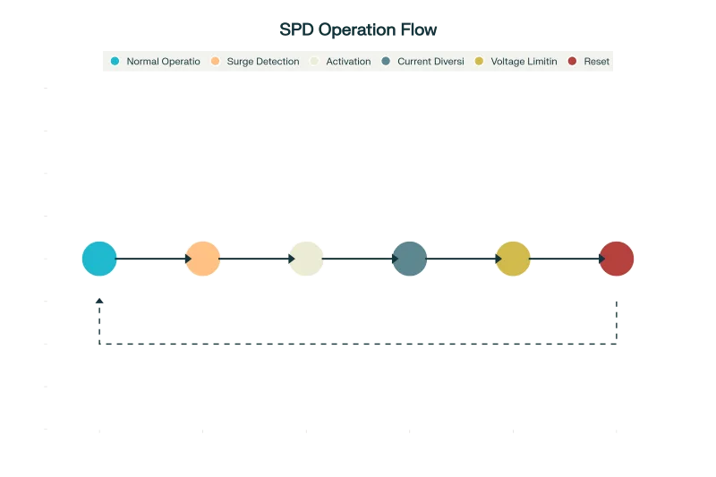
Med normalnimi obratovalnimi pogoji SPD-ji vzdržujejo stanje visoke impedance, običajno v območju gigaohmov, kar omogoča pretok minimalnega uhajanja toka, hkrati pa praktično nima vpliva na zaščiteno vezje. Ta način pripravljenosti zagotavlja, da SPD ne moti normalnega električnega delovanja, hkrati pa nenehno spremlja nivoje napetosti.
Ko pride do prehodne prenapetosti in preseže prag napetosti SPD-ja, se naprava hitro preoblikuje. V nanosekundah, SPD preide v stanje nizke impedance, s čimer ustvarite prednostno pot za udarni tok. To preklopno dejanje učinkovito preusmeri nevarni tok stran od občutljive opreme in ga varno usmeri v zemljo ali nazaj k njegovemu viru.
Spletna stran vpenjalni mehanizem je prav tako ključnega pomena, saj SPD-ji omejujejo velikost napetosti, ki doseže zaščiteno opremo. Namesto da bi dovolili prehod tisoč voltov, pravilno delujoč SPD napetost omeji na varno raven, običajno nekaj sto voltov, ki jo večina elektronske opreme lahko prenese brez poškodb.
Tehnologije SPD in njihovi mehanizmi preusmeritve
Na področju SPD prevladujejo tri glavne tehnologije, od katerih vsaka uporablja različne fizikalne mehanizme za doseganje omejitve napetosti in preusmeritve toka.
| Značilnost | Variator kovinskega oksida (MOV) | Plinska razelektritvena cev (GDT) | TVS dioda |
|---|---|---|---|
| Odzivni čas | 1–5 nanosekund | 0,1–1 mikrosekunde | 0,001–0,01 nanosekunde |
| Napetost vpenjanja | Spremenljivo s tokom | Nizka napetost obloka (~20 V) | Natančno, stabilno |
| Trenutna zmogljivost | Visoka (1–40 kA) | Zelo visoka (10+ kA) | Nizko do srednje (razpon A) |
| Mehanizem delovanja | ZnO zrna, napetostno odvisna upornost | Ionizacija plina ustvarja prevodno pot | Plazoviti razpad silicija |
| Tipične aplikacije | Zaščita daljnovodov, stanovanjski/poslovni SPD-ji | Telekomunikacije, visokoenergetske prenapetosti, primarna zaščita | Podatkovne linije, občutljiva elektronika, fina zaščita |
| Glavne prednosti | Visoka tokovna zmogljivost, dvosmerno, stroškovno učinkovito | Zelo nizko uhajanje, visoka tokovna zmogljivost, dolga življenjska doba | Najhitrejši odziv, natančna napetost, brez degradacije |
| Glavne omejitve | Sčasoma se razgradi, občutljiv na temperaturo | Počasnejši odziv, zahteva prekinitev sledilnega toka | Omejena trenutna zmogljivost, višji stroški |
Tehnologija kovinsko-oksidnih varistorjev (MOV)
Kovinski oksidni varistorji predstavljajo najpogosteje uporabljeno tehnologijo SPD, z več kot 96% SPD-jev za daljnovode z uporabo komponent MOV zaradi njihove zanesljivosti in robustnih lastnosti delovanja. MOV-i so sestavljeni iz zrna cinkovega oksida (ZnO) z dodatki, kot je bizmutov oksid (Bi₂O₃), ki ustvarjajo odpornost, odvisno od napetosti.
Fizika, na kateri temelji delovanje MOV, vključuje učinki meja zrn kjer kristalna struktura cinkovega oksida ustvarja naravne ovire za pretok toka pri normalnih napetostih. Ko napetost preseže napetost varistora (običajno izmerjeno pri 1 mA enosmernega toka), se te ovire porušijo, kar omogoča dramatično povečanje toka, hkrati pa ohranja relativno stabilno napetost na napravi.
Razstava MOV dvosmerne značilnosti, zaradi česar so enako učinkoviti tako pri pozitivnih kot negativnih napetostnih prehodnih pojavih. Njihova zmogljivost prenašanja visokega toka, pogosto ocenjena za Prenapetostni tokovi 1–40 kA, zaradi česar so idealni za primarne zaščitne aplikacije, kjer je treba varno preusmeriti velike tokove, ki jih povzroči strela.
Tehnologija plinskih razelektritvenih cevi (GDT)
Plinske cevi delujejo po bistveno drugačnem mehanizmu, ki temelji na fizika ionizacije plinovTe naprave vsebujejo inertne pline (kot sta neon ali argon), zaprte v keramičnih ohišjih z natančno razporejenimi elektrodami.
Pri normalni napetosti plin ohrani svoje izolacijske lastnosti, kar ima za posledico zelo visoka impedanca in izjemno nizek uhajalni tok. Ko pa napetost preseže prag iskrenja, ki se običajno giblje od sto do tisoč voltov, odvisno od zasnove, postane jakost električnega polja zadostna za ionizacijo molekul plina.
Proces ionizacije ustvarja prevodni plazemski kanal med elektrodama, kar učinkovito povzroči kratek stik prenapetosti in zagotovi pot z nizkim uporom (običajno okoli 20 V napetosti obloka) za pretok prenapetostnega toka. To preklopno dejanje se zgodi znotraj 0,1 do 1 mikrosekunde, zaradi česar so GDT-ji še posebej učinkoviti pri visokoenergijskih prenapetostnih dogodkih.
Tehnologija diod za dušenje prehodne napetosti (TVS)
TVS diode uporabljajo silicijev plaz fizika za doseganje izjemno hitrih odzivnih časov in natančnega vpenjanja napetosti. Te polprevodniške naprave so v bistvu specializirane Zenerjeve diode, optimizirane za aplikacije za dušenje prehodnih pojavov.
Mehanizem plaznega preboja se pojavi, ko električno polje znotraj silicijevega kristala postane dovolj močno, da pospeši nosilce naboja do energij, ki zadostujejo za udarno ionizacijo. Ta proces ustvari dodatne pare elektronov in vrzeli, kar vodi do nadzorovanega plaznega učinka, ki vzdržuje relativno konstantno napetost, hkrati pa prevaja naraščajoči tok.
TVS diode ponujajo najhitrejši odzivni časi katere koli SPD tehnologije, običajno 0,001 do 0,01 nanosekunde, zaradi česar so idealni za zaščito občutljivih podatkovnih linij in visokohitrostnih elektronskih vezij. Vendar pa je njihova zmogljivost prenosa toka običajno omejena na ampersko območje, kar zahteva skrbno načrtovanje uporabe.
Karakteristike napetosti in toka ter metrike delovanja
Učinkovitost tehnologij SPD pri omejevanju prehodnih napetosti je mogoče razumeti z njihovimi karakteristikami napetost-tok (VI), ki razkrivajo, kako se vsaka tehnologija odziva na naraščajoče prenapetostne tokove.
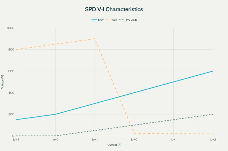
Omejevanje napetosti v primerjavi z obnašanjem preklapljanja napetosti
SPD-ji so glede na svoje VI značilnosti v osnovi razvrščeni v dve kategoriji: omejevanje napetosti in . preklapljanje napetosti naprave. Napetostno omejevalne naprave, kot so MOV in TVS diode, kažejo postopne spremembe impedance z naraščanjem napetosti, kar povzroči obnašanje stiskanja, kjer napetost zmerno narašča s tokom.
Napetostno preklopne naprave, kot so na primer GDT-ji, kažejo prekinitvene lastnosti z ostrim prehodom iz stanja visoke v stanje nizke impedance. To preklopno delovanje zagotavlja odlično izolacijo med normalnim delovanjem, vendar zahteva skrbno koordinacijo, da se preprečijo težave s nadaljnjim tokom.
Kritični parametri delovanja
Napetost vpenjanja predstavlja največjo napetost, ki jo SPD dovoljuje, da preide skozi zaščiteno opremo med prenapetostnim dogodkom. Ta parameter se meri v standardiziranih testnih pogojih, običajno z uporabo 8/20 mikrosekundnih tokovnih valov ki simulirajo značilnosti prenapetosti v resničnem svetu.
Odzivni čas določa, kako hitro se lahko SPD odzove na prehodne dogodke. Medtem ko se komponente za omejevanje napetosti običajno odzovejo znotraj nanosekundni razpon, lahko naprave za preklop napetosti zahtevajo mikrosekunde da se popolnoma aktivira. Pomembno je, da je odzivni čas komponent SPD, ki omejujejo napetost, podoben in znotraj nanosekundnega območja, zaradi česar sta dolžina vodnikov in dejavniki namestitve pomembnejša od razlik v odzivnem času komponent.
Prepustna napetost Meritve omogočajo praktično oceno delovanja SPD v realnih pogojih namestitve. Te vrednosti upoštevajo napetost, ki dejansko doseže zaščiteno opremo, vključno z učinki dolžina vodnika in impedanca namestitveŠtudije kažejo, da na prepustne napetosti bistveno vpliva dolžina vodnikov, zato standardizirano testiranje za primerjavo uporablja šestinčne dolžine vodnikov.
Strategije za namestitev in koordinacijo SPD
Učinkovita prenapetostna zaščita zahteva strateško postavitev in koordinacijo več SPD naprav v električnih sistemih. Koncept kaskadna zaščita vključuje namestitev različnih vrst SPD-jev na različnih točkah v električnem distribucijskem sistemu, da se zagotovi celovita pokritost.
Tristopenjska strategija zaščite
SPD tipa 1 so nameščeni na servisnem vhodu za ravnanje neposredni udari strele in visokoenergijske prenapetosti iz komunalnih sistemov. Te naprave morajo prenesti 10/350 mikrosekundnih tokovnih valov ki simulirajo visoko energijsko vsebnost udarov strele, pri čemer nazivni tok pogosto presega 25 kA.
SPD tipa 2 zagotavljajo zaščito na razdelilnikih pred posredni udari strele in preklopnih prenapetosti. Preizkušeno z 8/20 mikrosekundnih valovnih oblikTe naprave obvladujejo preostale prenapetosti, ki prehajajo skozi zaščito pred napetostjo, hkrati pa zagotavljajo nižje napetosti vpenjanja za izboljšano zaščito opreme.
SPD tipa 3 ponudba zaščita na mestu uporabe za občutljivo opremo, ki zagotavlja zadnjo obrambno linijo z najnižjimi možnimi napetostmi vpenjanja. Te naprave so običajno nameščene znotraj 10 metrov od zaščitene opreme, da se čim bolj zmanjšajo učinki impedance priključnih vodnikov.
Izzivi in rešitve pri usklajevanju
Uspešna koordinacija med kaskadnimi SPD-ji zahteva skrbno pozornost ravni zaščite pred napetostjo in . električna ločitevTemeljni izziv je zagotoviti, da naprave pred nami obvladujejo večino prenapetostne energije, medtem ko naprave za nami zagotavljajo natančno zaščito, ne da bi bile preobremenjene.
Raziskave kažejo, da je koordinacija najučinkovitejša, kadar imajo kaskadni SPD-ji podobne ravni napetostne zaščiteKadar obstajajo znatne razlike med napetostjo vpenjanja pred in za priključkom, lahko naprava z nižjo napetostjo poskuša prevajati večino udarnega toka, kar lahko povzroči prezgodnjo odpoved.
Spletna stran induktivnost ožičenja med lokacijami SPD zagotavlja naravno ločitev, ki pomaga pri koordinaciji. Ta induktivnost ustvarja padce napetosti med prenapetostnimi dogodki, ki pomagajo ustrezno porazdeliti energijo med več stopnjami SPD, pri čemer daljše ločilne razdalje na splošno izboljšajo učinkovitost koordinacije.
Mehanizmi absorpcije in disipacije energije
Zaščitni napajalniki SPD ne smejo le preusmerjati udarnih tokov, temveč tudi varno absorbirati in razpršiti s tem povezano energijo, ne da bi pri tem ustvarjali sekundarne nevarnosti. Zmogljivost SPD za obvladovanje energije je odvisna od več dejavnikov, vključno z amplitudo in trajanjem udarnih tokov ter specifičnimi mehanizmi absorpcije energije različnih tehnologij.
Disipacija energije v MOV-ih se zgodi skozi Joulovo ogrevanje znotraj strukture zrn cinkovega oksida. Nelinearne uporovne karakteristike zagotavljajo, da se večina energije razprši med visokim tokom v času prenapetosti, pri čemer se naprava vrne v stanje visoke impedance, ko se tok zmanjša. Vendar pa lahko ponavljajoči se dogodki z visoko energijo povzročijo kumulativna degradacija materiala MOV, kar sčasoma vodi do povečanega uhajanja toka in zmanjšane učinkovitosti zaščite.
GDT-ji razpršijo energijo skozi ionizacijski in deionizacijski procesi znotraj plinskega medija. Obločni razelektritev učinkovito pretvarja električno energijo v toploto in svetlobo, pri čemer plinski medij zagotavlja odlične lastnosti okrevanja po prenapetosti. Keramična konstrukcija in plinski medij zagotavljata GDT-jem odlično vzdržljivost pri ponavljajočih se prenapetostnih dogodkih brez večje degradacije.
Varnostni vidiki in načini odpovedi
Varnost SPD-jev presega normalno delovanje in vključuje tudi delovanje med okvarami. Razumevanje možnih načinov okvare je ključnega pomena za zagotovitev, da SPD-ji izboljšajo in ne ogrozijo varnost sistema.
Načini odpovedi odprtega tokokroga
Napake odprtega tokokroga običajno se pojavijo, ko SPD-ji dosežejo konec življenjske dobe ali se aktivira termična zaščita. SPD-ji, ki temeljijo na MOV, pogosto vključujejo termični ločilniki ki napravo fizično ločijo od tokokroga, ko pride do prekomernega segrevanja, in tako preprečijo morebitno nevarnost požara.
Izziv pri napakah odprtega tokokroga je v zaznavanje in indikacijaOkvarjeni SPD-ji v načinu odprtega tokokroga pustijo sisteme nezaščitene, vendar ne dajejo takojšnjega znaka izgube zaščite. Sodobni SPD-ji vse pogosteje vključujejo indikacija stanja funkcije, vključno z LED indikatorji in kontakti za oddaljeni alarm, ki uporabnike opozorijo, ko je potrebna zamenjava.
Premisleki glede kratkega stika
Kratki stiki predstavljajo bolj neposredne varnostne pomisleke, saj lahko ustvarijo trajne kratkostične tokove, ki lahko povzročijo delovanje naprave zaradi preobremenitve ali nevarnost požara. Prenapetostni odklopniki morajo biti podvrženi strogim preskus kratkostične vzdržnosti v skladu s standardi, kot je IEC 61643-11, da se zagotovijo varni načini odpovedi.
Zunanja zaščita pred preobremenitvijo Zagotavlja ključno rezervno zaščito pred kratkimi stiki. Pravilno usklajene varovalke ali odklopniki lahko prekinejo tokove okvare, hkrati pa omogočajo normalno delovanje SPD, študije usklajevanja pa zagotavljajo, da zaščitne naprave ne motijo funkcij prenapetostne zaščite.
Standardi in zahteve glede testiranja
Načrtovanje, testiranje in uporabo SPD urejajo celoviti standardi, ki zagotavljajo dosledno delovanje in varnost. Globalne zahteve SPD prevladujeta dva glavna okvira standardov: UL 1449 (predvsem severnoameriški) in IEC 61643 (mednarodno).
Ključni parametri testiranja
Testiranje po standardu UL 1449 poudarja Napetostna zaščita (VPR) meritve s kombiniranim valovnim testiranjem (napetost 1,2/50 μs, tok 8/20 μs). Standard zahteva Preizkus nazivnega toka praznjenja (In) s 15 impulzi pri nazivnem toku za preverjanje zanesljivosti delovanja.
Testiranje po IEC 61643 uvaja dodatne parametre, vključno z testiranje impulznega toka (Iimp) za SPD-je tipa 1 z uporabo valovnih oblik 10/350 μs za simulacijo energijske vsebine strele. Standard poudarja tudi raven zaščite napetosti (Up) meritve in zahteve glede koordinacije med različnimi tipi SPD.
Zahteve za namestitev in varnost
Standardi za vgradnjo določajo posebne varnostne zahteve, vključno z pravilna ozemljitev, zmanjševanje dolžine svincain usklajevanje z zaščitnimi napravamiZaščitne pretvornike mora namestiti usposobljeni električarji upoštevajte ustrezne varnostne postopke, saj so v ohišjih SPD prisotne nevarne napetosti.
Zahteve za ozemljitev so še posebej kritični, saj nepravilna vezava nevtralnega in ozemljenega vodnika predstavlja Glavni vzrok okvar SPDStandardi za vgradnjo zahtevajo preverjanje ustrezne ozemljitve pred vklopom SPD in predpisujejo odklop med testiranjem visoke napetosti, da se prepreči poškodba.
Ekonomske in zanesljivostne prednosti
Ekonomska upravičenost vgradnje SPD sega daleč preko začetnih naložbenih stroškov in zajema zaščito opreme, preprečevanje izpadov in izboljšanje obratovalne zanesljivosti.
Analiza stroškov in koristi
Študije kažejo, da Škoda zaradi prenapetosti stane ameriško gospodarstvo od 1 do 5 milijard dolarjev letno. že samo zaradi incidentov, povezanih s strelo. Namestitev SPD zagotavlja stroškovno učinkovito zavarovanje pred temi izgubami, pri čemer začetna naložba običajno predstavlja le majhen del potencialnih stroškov zamenjave opreme.
Stroški obratovalnih izpadov pogosto presegajo neposredne stroške poškodb opreme, zlasti v komercialnih in industrijskih okoljih. SPD-ji pomagajo ohranjati neprekinjeno poslovanje s preprečevanjem okvar zaradi prenapetosti, ki bi lahko motile kritično delovanje.
Podaljšanje življenjske dobe opreme
SPD-ji prispevajo k podaljšana življenjska doba opreme s preprečevanjem kumulativne škode zaradi ponavljajočih se majhnih prenapetosti. Čeprav posamezni dogodki prenapetosti morda ne povzročijo takojšnje okvare, kumulativna obremenitev pospeši degradacijo komponent in zmanjša splošno zanesljivost opreme.
Raziskave kažejo, da imajo objekti, opremljeni s celovito izkušnjo zaščite SPD bistveno nižje stopnje okvar opreme in zmanjšane zahteve glede vzdrževanja. To se odraža v izboljšani zanesljivosti sistema in nižjih skupnih stroških lastništva električnih in elektronskih sistemov.
Prihodnji razvoj in aplikacije
Razvoj tehnologije SPD še naprej obravnava nastajajoče izzive v sodobnih električnih sistemih, vključno z integracija obnovljivih virov energije, infrastruktura za polnjenje električnih vozilin aplikacije pametnih omrežij.
Zaščita pred prenapetostjo enosmernega toka je pridobil na pomenu s širjenjem fotovoltaičnih sistemov in polnilnih postaj z enosmernim tokom. Specializirani SPD-ji, zasnovani za uporabo z enosmernim tokom, morajo obravnavati edinstvene izzive, vključno z izumrtje loka brez prehodov AC skozi ničlo in koordinacija z zaščitnimi napravami za enosmerni tok.
Komunikacija in varstvo podatkov Zahteve se še naprej širijo z naraščajočo odvisnostjo od omrežnih sistemov. Napredne tehnologije SPD morajo zagotavljati zaščito za visokohitrostne podatkovne linije hkrati pa ohranja integriteto signala in zmanjšuje izgubo zaradi vstavljanja.
Zaključek
Naprave za prenapetostno zaščito predstavljajo ključno obrambo pred nenehno prisotno grožnjo prehodnih prenapetosti v sodobnih električnih sistemih. Z dovršenimi mehanizmi, ki vključujejo napetostno odvisne materiale, fiziko ionizacije plinov in učinke polprevodniških plazov, SPD uspešno preusmerjajo nevarne prenapetostne tokove in omejujejo napetosti na varne ravni.
Učinkovitost zaščite SPD je odvisna od pravilne izbire tehnologije, strateške namestitve in skrbne koordinacije med več stopnjami zaščite. Medtem ko posamezne tehnologije SPD ponujajo edinstvene prednosti, celovita zaščita običajno zahteva usklajen pristop, ki združuje različne tehnologije na ustreznih lokacijah sistema.
Ker električni sistemi postajajo vse bolj kompleksni in odvisni od občutljivih elektronskih komponent, bo vloga SPD-jev pri zagotavljanju varnosti in zanesljivosti le še naraščala. Nadaljnji napredek tehnologije SPD-jev, skupaj z izboljšanimi praksami namestitve in programi vzdrževanja, bo bistvenega pomena za zaščito kritične infrastrukture, ki je temelj sodobne družbe.
Ekonomske koristi zaščite SPD daleč odtehtajo začetne stroške naložbe, zaradi česar je prenapetostna zaščita bistvena komponenta odgovornega načrtovanja električnih sistemov. Z razumevanjem, kako SPD preusmerjajo in omejujejo prehodne napetosti, lahko inženirji in upravljavci objektov sprejemajo premišljene odločitve, ki ščitijo dragoceno opremo, zagotavljajo neprekinjeno delovanje in ohranjajo varnost električnih inštalacij.
Povezano
Kaj je naprava za prenapetostno zaščito (SPD)
