
You’ve done everything right.
The MOV surge protector is rated for 275V, properly sized for your 240V system, installed exactly per the wiring diagram—parallel with the load, just like every application note shows. You even added it to your panel schedule and documented it for the inspector.
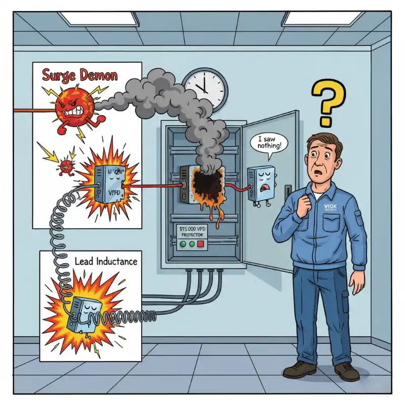
Then the storm hits. Lightning finds your service entrance at 2:47 AM. By the time you get the call, production has been down for three hours, and that $15,000 variable frequency drive you commissioned last month? It’s dead. Fried circuit boards, burnt smell, the whole catastrophe. But here’s the thing that doesn’t make sense: the MOV is still sitting in the panel, cool to the touch, showing zero signs of damage. No blown fuse. No thermal discoloration. It looks like it never even knew there was a surge.
So what happened? If the MOV was wired in parallel with the load—and you learned in circuits class that parallel branches see the same voltage—how was it ever supposed to protect anything?
The answer is hiding in plain sight. Or more accurately, it’s hiding because it’s not in sight—it’s not even on the circuit diagram.
Why MOV Protection Seems Impossible (According to Circuit Theory)
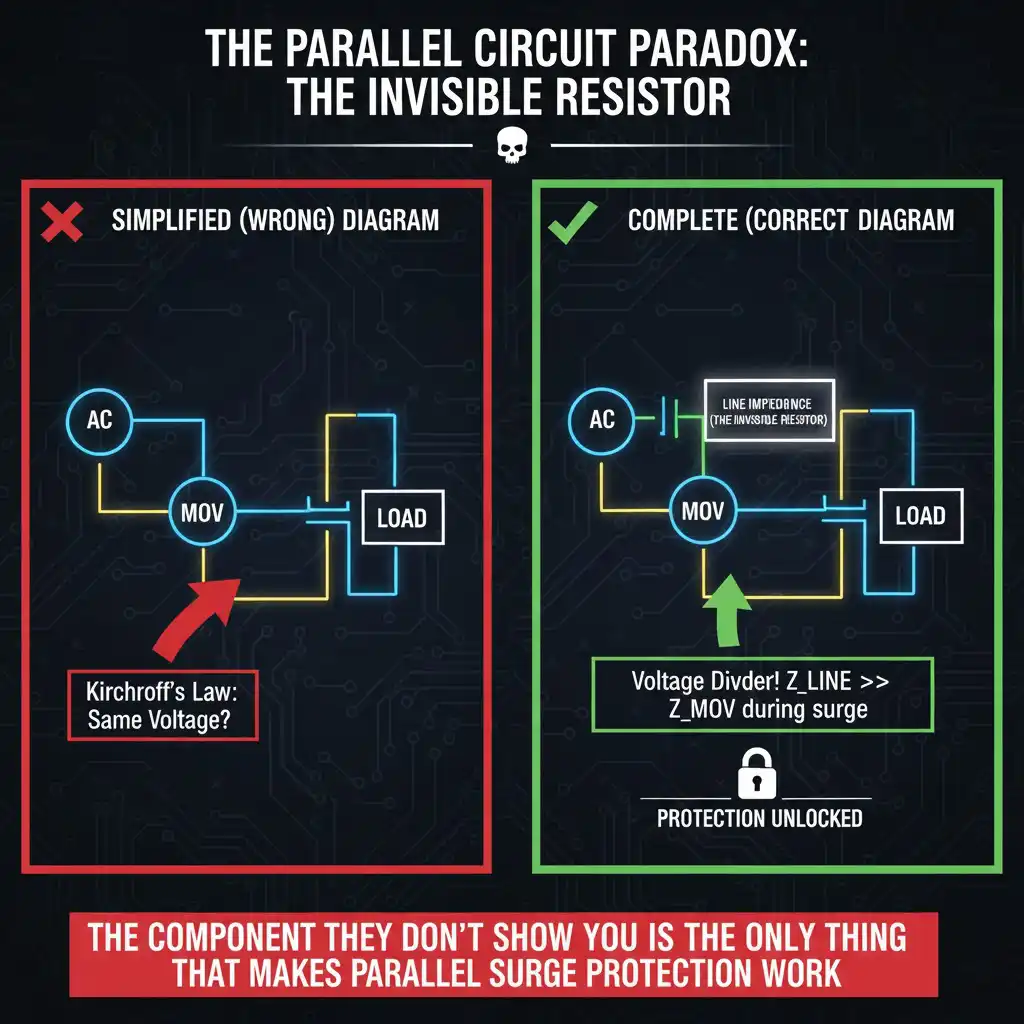
Here’s the circuit diagram you’ve seen a hundred times:
AC source → MOV in parallel with load → that’s it.
Every electrical engineer knows the fundamental rule: components in parallel experience the same voltage. It’s literally Kirchhoff’s Voltage Law—go around any closed loop, and the voltage drops must sum to zero. So if your AC source surges to 1,000V, and the MOV is in parallel with your equipment, then your equipment sees… 1,000V. The MOV might start conducting heavily, dropping its resistance from megohms down to a few ohms, but so what? It’s in parallel. The voltage across both branches is identical.
This is the Parallel Circuit Paradox.
The circuit diagram suggests the MOV should be useless. Drawing more current through the varistor branch doesn’t change the voltage across the load branch. You learned this in sophomore year. Your simulation software confirms it. And yet… somehow… MOV-based surge protection actually works. Millions of buildings use this exact configuration. Standards bodies recommend it. Manufacturers sell billions of dollars of these devices annually.
Either every circuit diagram is wrong, or you’re missing something fundamental.
Spoiler: You’re missing something.
The Component Missing from Every Circuit Diagram
The thing that makes MOV protection work—the component that breaks the Parallel Circuit Paradox—isn’t shown in simplified circuit diagrams because it’s always there. It’s so fundamental, so unavoidable, that drawing it every time would be like labeling every glass of water with “Warning: Contains Hydrogen.”
It’s the line impedance. The Invisible Resistor.
Between your AC source (utility transformer, backup generator, whatever) and your MOV-protected load, there’s always resistance and inductance in the wiring, connections, breakers, busbars, and the source itself. At 60 Hz steady-state, this impedance is tiny—often well under an ohm—and you can usually ignore it. Your lights don’t dim noticeably when you turn on a motor. Your multimeter measures pretty much the same voltage everywhere in the panel.
But during a surge?
During a surge, that “tiny” impedance becomes the most important component in your entire protection system.
Here’s why: The Invisible Resistor isn’t in parallel with anything—it’s in series with everything. And when the MOV starts conducting hard, pulling thousands of amps, that series impedance creates a voltage drop that didn’t exist at steady state. Suddenly, you don’t have two parallel branches at the same voltage. You have a voltage divider.
Here’s why with real numbers, because this is where it gets interesting.
The 2-Ohm Rule
The UL 1449 surge test standard for residential/light commercial SPDs specifies a source impedance of 2 ohms. This isn’t arbitrary—it’s based on measurements of actual residential service entrance impedances. When you test an SPD, you’re simulating what happens when a 6,000V open-circuit surge (imagine a nearby lightning strike) hits a system with 2Ω of line impedance, which can deliver up to 3,000A of short-circuit surge current.
Watch what happens:
Surge hits. The MOV’s voltage-current characteristic means that once voltage exceeds its rated clamping voltage (let’s say 775V for a 275V-rated MOV), it starts conducting heavily. Its dynamic resistance during conduction might drop to under 1Ω. The surge current wants to flow, but it has to push through that 2Ω of line impedance first.
Voltage divider formula: V_load = V_surge × (Z_MOV / (Z_line + Z_MOV))
With a 3,000A surge and our 2Ω line impedance:
Voltage drop across line impedance: 3,000A × 2Ω = 6,000V
Voltage at the MOV/load node: V_surge – 6,000V
Wait. If we started with a 6,000V surge, and we drop 6,000V across the line impedance, what’s left at the load?
Almost nothing. The MOV clamps what little voltage does appear, typically to around 775V for this rating. Your equipment, if it’s rated for proper surge withstand (typically 1,500V-2,500V for industrial gear), survives easily.
The Invisible Resistor just absorbed 6,000V so your MOV only had to deal with 775V.
That’s why the parallel configuration works. The MOV isn’t protecting by “keeping voltage the same”—it’s protecting by creating a voltage divider with the line impedance. The line impedance isn’t a problem to work around. It’s the solution.
Why ‘Properly Installed’ SPDs Still Let Equipment Get Destroyed
So if The Invisible Resistor makes everything work, why do SPDs fail? Why did that $15,000 VFD still get fried?
Because The Invisible Resistor has to be big enough, in the right place, and paired with an MOV that’s actually still working. Miss any of these, and your “protection” is theoretical only.
Reason #1: You Don’t Have Enough Line Impedance
The Impedance Budget is what I call the total series impedance between the surge source and your load. Too little, and the voltage division doesn’t work. The MOV gets overwhelmed, and the load gets exposed.
This happens in three scenarios:
Scenario A: Too close to the transformer
If your facility is 50 feet from the utility pole transformer, your line impedance might be only 0.5Ω. When that 3,000A surge hits, you drop only 1,500V across the line impedance. If the surge started at 6,000V, you’ve got 4,500V showing up at your MOV. A 275V-rated MOV clamping at 775V can’t handle that—it’s trying to absorb 3,725V more than it’s designed for. It’ll conduct, hard, but the clamping voltage will be much higher than rated, and your equipment might not survive.
Scenario B: Very stiff source
Large commercial buildings with multiple transformer feeds or facilities with on-site generators often have source impedances under 0.3Ω. Voltage stability? Excellent. Motor starting? Smooth. Surge protection? Terrible. The voltage division barely happens.
Scenario C: Service entrance SPD on wrong side of main breaker
Install an SPD on the line side of the main breaker (which some electricians do, thinking they’re protecting “everything”), and you lose the breaker’s contact resistance and connection impedance from your Impedance Budget. That might cost you 0.3-0.5Ω of protection—enough to matter.
Pro-Sfat #1:
Your protection is only as good as your line impedance. If you’re within 100 feet of the transformer or have a very stiff source (>10,000A available short-circuit current), a single MOV at the service entrance won’t be enough. You need coordinated, layered protection.
Reason #2: The SPD is Too Far from What You’re Protecting
Here’s the counterintuitive part: distance from the source adds to your Impedance Budget (good for voltage division), but distance from the SPD to the load subtracts from your protection (bad for the load).
If your service entrance SPD is 200 feet of conduit away from your critical equipment, there’s line impedance between the SPD and the load too. That impedance is after the protection point. The SPD clamps voltage at the panel to, say, 800V. But the surge current still has to push through another 200 feet of wire to reach your VFD, and that wire has impedance.
Let’s calculate:
200 feet of 3/0 AWG copper in steel conduit ≈ 0.05Ω resistance + 0.1Ω inductive reactance (at surge frequencies) ≈ 0.15Ω
Surge current: 1,000A (reduced from 3,000A by the service entrance protection)
Additional voltage rise at the load: 1,000A × 0.15Ω = 150V
Voltage at VFD: 800V + 150V = 950V
If your VFD is rated for 800V surge withstand, you just exceeded it. That 200 feet just added 150V of unprotected exposure—more than enough to damage sensitive electronics.
This is why industrial facilities use layered protection: service entrance SPD (Type 1 per IEC 61643-11), subpanel SPD (Type 2), and load-side SPD (Type 3). Each layer has line impedance working in its favor, and you minimize the unprotected impedance between SPD and load.
Pro-Sfat #2:
Calculate before you install. Use the voltage divider formula with line impedance to predict actual clamping voltage at the load, not just at the SPD. If the distance is significant, you need additional protection closer to the load.
Reason #3: Your MOV is Worn Out (And You Don’t Know It)
MOVs don’t last forever. Every surge event, even small ones, causes microscopic damage to the zinc oxide grain boundaries inside the device. Over time, the clamping voltage increases. That 275V-rated MOV you installed seven years ago might now clamp at 1,200V instead of 775V.
The failure mode looks like this:
Years of small surge events gradually degrade the MOV
Clamping voltage slowly increases (you don’t notice because you’re not testing it)
One day, a large surge hits
The worn MOV clamps at 1,500V instead of 775V
Your equipment, rated for 1,200V withstand, gets damaged
You check the MOV—it looks fine, no visible damage, fuse hasn’t blown
Eventually, a severely degraded MOV will fail short-circuit. This is actually the designed failure mode—better to fail short and blow the fuse than fail open and provide zero protection. But if the fuse isn’t properly coordinated, a shorted MOV at the end of its life can pull enough current to overheat connections or even start a fire.
Those “lifetime warranty” whole-house SPDs? The fine print usually says the MOV is sacrificial and needs inspection every 2-3 years in high-surge environments (Florida, mountain regions, near industrial facilities). Nobody does this.
Pro-Sfat #3:
Don’t trust a 10-year-old MOV. Energy absorption degrades the clamping voltage over time—that 275V MOV might now clamp at 400V or higher. Replace SPDs every 5-7 years in harsh environments, 10 years maximum elsewhere.
The Impedance Budget: Calculating Real-World Protection
Enough theory. Let’s calculate whether your SPD will actually protect your equipment.
Step 1: Estimate Your Line Impedance
You need to estimate the total series impedance from the surge injection point (usually the service entrance) to the SPD location. This includes:
- Utility source impedance (transformer + service drop)
- Service entrance conductors
- Main breaker/disconnect contact resistance
- Busbar impedance
- Feeder conductors to panel where SPD is located
Typical values for conservative design:
| Tip de instalare | Typical Line Impedance | Short-Circuit Current |
|---|---|---|
| Residential, close to transformer (<100ft) | 0.5 – 1.0Ω | 12,000 – 24,000A |
| Residential, standard distance | 1.5 – 2.5Ω | 4,800 – 8,000A |
| Light commercial, 208/120V | 0.3 – 0.8Ω | 15,000 – 40,000A |
| Industrial, 480V, medium source | 0.1 – 0.3Ω | 40,000 – 120,000A |
| Industrial, 480V, very stiff source | 0.05 – 0.15Ω | 80,000 – 200,000A |
If you need more accuracy, measure the short-circuit current at your panel (requires specialized equipment), then calculate:
Z_line = V_nominal / I_SC
For example: 240V nominal, 10,000A short-circuit current → Z_line = 240V / 10,000A = 0.024Ω
Wait, that’s way less than the residential 2Ω we talked about earlier! What gives?
Different timescales. That short-circuit current is the 60 Hz steady-state fault current, where only resistive and 60 Hz inductive reactance matter. For surges with rise times of 1-8 microseconds, the effective impedance is much higher because of:
- Higher frequency inductive reactance (XL = 2πfL, and f is effectively in the MHz range for microsecond surges)
- Skin effect in conductors
- Distributed capacitance and inductance in the wiring
The difference can be 50-100x. That’s why 0.024Ω at 60 Hz becomes 2Ω at surge frequencies.
For design purposes, use the table above. The standards committees already factored in the frequency effects.

Step 2: Calculate Voltage Division During Surge
Standard surge test is 6kV open circuit, with enough source impedance to deliver 3,000A into a short circuit. This is The 2-Ohm Rule—6kV / 3kA = 2Ω.
The voltage at your load is determined by the voltage divider between line impedance and MOV dynamic resistance during conduction:
V_load ≈ V_clamp_MOV + (I_surge × Z_remaining)
Unde:
- V_clamp_MOV = MOV clamping voltage from datasheet (typically 2.5-3x rated voltage)
- I_surge = surge current (limited by total impedance)
- Z_remaining = any impedance between SPD and load
Worked Example 1: Residential, standard installation
System: 240V single-phase
Line impedance: 2.0Ω (standard residential per UL 1449 test conditions)
MOV rating: 275V (clamping voltage: 775V typical)
Surge: 6kV open circuit
SPD location: Main panel
Load location: 50 feet away in subpanel
Surge current: I = V_surge / (Z_line + Z_MOV_dynamic)
Assuming MOV dynamic resistance ≈ 1Ω during heavy conduction:
I = 6,000V / (2Ω + 1Ω) = 2,000A
Voltage at main panel (at SPD): V_clamp = 775V (MOV datasheet value)
Voltage drop from main panel to subpanel:
50 ft of 3/0 AWG copper: ~0.08Ω (including surge frequency effects)
Additional voltage rise: 2,000A × 0.08Ω = 160V
Voltage at subpanel load: 775V + 160V = 935V
Conclusion: If your equipment is rated for 1,200V surge withstand (typical for quality industrial electronics), you’re protected with comfortable margin. If it’s only rated for 800V (cheaper equipment), you need an additional SPD at the subpanel.
Worked Example 2: Industrial, stiff source
System: 480V three-phase
Line impedance: 0.15Ω (very close to large transformer)
MOV rating: 510V (clamping voltage: 1,400V typical)
Surge: 6kV, standard test
SPD location: Main switchgear
Load location: Critical VFD 300 feet away
Surge current with stiff source: I = 6,000V / (0.15Ω + 1Ω) = 5,217A
Voltage at main switchgear: V_clamp = 1,400V (but MOV might struggle with the high current and clamp higher, say 1,800V due to saturation effects)
Voltage drop to VFD:
300 ft of 250 kcmil copper: ~0.15Ω
Additional voltage: 5,217A × 0.15Ω = 782V
Voltage at VFD: 1,800V + 782V = 2,582V
Conclusion: This is a problem. The Impedance Budget is insufficient. You need layered protection:
- Service entrance SPD to take the initial hit
- Let line impedance build up over distance (now it’s your friend)
- Add a second SPD at the VFD subpanel (now you have 0.15Ω working for you between layers)
With two-layer protection, the math changes:
Layer 1 clamps to 1,800V at service entrance
300 feet adds impedance → reduced surge current reaches Layer 2
Layer 2 SPD at VFD location clamps to 800V
VFD sees 800V (safe)
Step 3: Verify Against Equipment Withstand
Check your equipment surge withstand voltage rating:
- Industrial VFDs: typically 2,500-4,000V per NEMA MG1 / IEC 61800-5-1
- PLCs and industrial controls: typically 1,500-2,500V
- Consumer electronics: 600-1,000V
- Office IT equipment: 800-1,200V
- Motors (coil insulation): 3,000-5,000V
You need safety margin: aim for calculated surge voltage at load to be ≤70% of equipment withstand rating.
If your calculation exceeds this, you need:
- Additional SPD closer to load (adds more favorable impedance)
- Higher-energy SPD at service entrance (better clamping)
- Coordination between SPDs (Type 1 + Type 2 + Type 3 cascade)
Pro-Tip #4:The best surge protection uses impedance as a weapon, not an obstacle. Space your SPDs to accumulate line impedance between them—each 100 feet of separation adds protection for the downstream device.
Using the Invisible Resistor as a Weapon: Coordinated Protection Strategy
Most engineers think about surge protection as a problem to solve: “How do I stop surges from reaching my equipment?” That’s defensive thinking, and it leads to single-point-of-failure designs.
Better question: “How do I use the line impedance in my installation to distribute surge energy across multiple protection devices, each working in its optimal operating region?”
Now you’re weaponizing The Invisible Resistor.
Layer 1: Service Entrance Protection (Let Impedance Work FOR You)
Install a high-energy Type 1 SPD at your service entrance or main distribution panel. This device needs to handle the initial surge energy—potentially 10-20 kJ per mode—because it sees the full surge before any meaningful line impedance attenuates it.
Key specifications for Layer 1:
- Voltage rating: 275V for 208/240V systems, 510V for 480V systems
- Energy rating: ≥10 kJ per mode (L-N, L-G, N-G)
- Maximum discharge current (Imax): ≥40 kA per mode
- Response time: <1 nanosecond (MOVs achieve this inherently)
- Configuration: All modes protected (L-N, L-G, N-G for single-phase; all combinations for three-phase)
The service entrance SPD does two things:
- Clamps the surge to a manageable level (say, 1,500V)
- Gives line impedance between the service entrance and downstream loads a chance to work
Think of it as taking the first hit so downstream devices face a reduced threat. The surge leaves your service entrance SPD heading toward your loads, but now it’s moving through 100, 200, 300 feet of conduit. That wire impedance is accumulating, dropping voltage, doing the work of protection without you even thinking about it.
Layer 2: Load-Side Protection (Minimize Remaining Exposure)
Install medium-energy Type 2 SPDs at subpanels or distribution points closer to sensitive loads. These devices see a pre-attenuated surge (thanks to Layer 1 + line impedance) and provide a second layer of clamping.
Key specifications for Layer 2:
- Voltage rating: Same as Layer 1 (275V or 510V)
- Energy rating: 5-10 kJ per mode (less than Layer 1 because surge is pre-attenuated)
- Maximum discharge current: 20-40 kA per mode
- Installation: At subpanels feeding sensitive equipment (VFDs, PLCs, control systems)
The magic here is coordination. Layer 1 clamps to 1,500V. Then 150 feet of wire impedance drops another 300V (assuming reduced surge current after Layer 1). Layer 2 SPD sees 1,200V and clamps to 800V. Your equipment, rated for 1,500V, sees 800V with comfortable margin.
VIOX offers coordinated SPD solutions specifically designed for layered protection in industrial environments—Type 1 and Type 2 devices with matched clamping voltages to ensure proper cascade operation without SPD-to-SPD stress.
Layer 3 (Optional): Point-of-Use Protection
For extremely sensitive or expensive equipment (CNC controllers, robotic systems, medical devices), add a final Type 3 SPD directly at the equipment enclosure. These are low-energy devices (1-3 kJ) with very tight clamping voltages.
By the time a surge reaches Layer 3, it’s been reduced to a manageable bump by Layers 1 and 2 plus all the accumulated line impedance. Layer 3 just cleans up the remainder.
Fuse Coordination: When MOVs Fail (Because They Will)
MOVs wear out. When they fail, they typically fail short-circuit. This is by design—better to blow a fuse than leave equipment unprotected—but it means you need properly rated fuses.
The Fast and the Fused: The surge is fast (1-2 microsecond rise time), but the fuse is slow (milliseconds to open). The fuse doesn’t protect against the surge—it protects against a failed MOV drawing continuous power-frequency current and overheating.
Fuse selection criteria:
- Fast-acting or semi-lag fuse (Class J or RK1 for best coordination)
- Rated for the maximum continuous MOV leakage current (typically <1 mA, but check datasheet)
- I²t rating lower than MOV’s maximum short-circuit withstand (so fuse opens before MOV explodes)
- For 275V MOV: typically 10-15A fuse
- For 510V MOV: typically 15-20A fuse
The fuse also simplifies replacement. When an MOV fails short after years of service, the fuse blows, you get an obvious failure indicator (dead SPD status light), and you swap the module. Without the fuse, a failed MOV might just sit there conducting, slowly cooking, until something catches fire.
Inspection schedule:
- Every 6 months: Visual inspection for physical damage or thermal discoloration
- Every 2 years: Leakage current test (should be <1 mA; if >5 mA, replace MOV)
- Every 5-7 years: Preventive replacement in high-surge environments (coastal, mountainous, near industrial facilities)
- After any direct lightning strike: Replace affected SPDs even if they “look fine”
The Protection You Couldn’t See Was the Protection You Needed
That $15,000 VFD didn’t fail because your MOV was defective. It failed because nobody accounted for The Invisible Resistor—the line impedance that determines whether your surge protection works at all or just sits there looking pretty while your equipment gets fried.
The Parallel Circuit Paradox isn’t really a paradox. It’s just incomplete. The circuit diagrams that show MOVs in simple parallel with loads are lying by omission. They’re leaving out the series impedance that makes the entire protection scheme function.
Now you know:
- Your Impedance Budget determines your protection effectiveness (more is better, up to a point)
- Distance from SPD to load matters (every foot of wire adds unprotected impedance)
- Layered protection uses line impedance offensively (service entrance + subpanel + load-side)
- MOVs wear out (inspect regularly, replace proactively)
The best part? That “imperfect” wiring you’ve been cursing—the long runs, the multiple connection points, the voltage drop you’re always trying to minimize? For surge protection, those are features, not bugs. The Invisible Resistor is working for you every single time.
Just make sure it’s big enough, in the right place, and paired with MOVs that are actually still working.
Want to calculate your facility’s Impedance Budget and deploy coordinated protection that actually works? VIOX’s technical team can help you design a layered SPD strategy based on your actual source impedance, load locations, and equipment withstand ratings. [Contact us for a free surge protection assessment →]
And next time someone asks how an MOV in parallel can possibly protect the load?
Just smile and say: “It’s the component you can’t see that makes all the difference.”


Standards & Sources Referenced
- UL 1449: Standard for Surge Protective Devices (Fourth Edition, current)
- IEC 61643-11: Low-voltage surge protective devices – Part 11: Surge protective devices connected to low-voltage power systems (2024 revision)
- IEEE C62.41: IEEE Recommended Practice on Surge Voltages in Low-Voltage AC Power Circuits
- NEMA MG 1: Motors and Generators (surge withstand specifications)
- IEC 61800-5-1: Adjustable speed electrical power drive systems – Part 5-1: Safety requirements
Timeliness Statement:
All product specifications, standards, and technical calculations accurate as of November 2025.
