
Every time you plug your smartphone charger into the wall, charge your laptop, or flip a light switch, you’re relying on one of the most ingenious electrical devices ever invented: the transformer. These silent workhorses of the electrical world make it possible for the high-voltage electricity traveling through power lines to safely power the devices in your home.
But how does an electrical transformer work? The answer lies in a fascinating principle discovered nearly 200 years ago that continues to power our modern world. In this comprehensive guide, you’ll discover exactly how transformers work, why they’re essential for electrical power distribution, and how the principle of electromagnetic induction makes it all possible.
Whether you’re a student learning about electrical engineering, a curious homeowner, or a professional seeking a refresher, this guide will take you from basic concepts to advanced applications—all explained in clear, accessible language.
The Simple Answer: Transformers Use “Magnetic Magic”
Think of voltage like water pressure in your pipes. Just as you might need a pressure reducer to safely connect a garden sprinkler to a high-pressure main line, electrical transformers work by changing voltage levels to make electricity safe and usable for different applications.
Here’s the simple version: transformers use electromagnetic induction to transfer electrical energy from one circuit to another while changing the voltage. They accomplish this remarkable feat without any moving parts, using only the invisible force of magnetism to “step up” or “step down” voltage levels.
The “magic” happens when alternating current flowing through one coil of wire creates a changing magnetic field that induces voltage in a second, completely separate coil. No direct electrical connection needed—just the power of electromagnetic induction discovered by Michael Faraday in 1831.
But here’s where it gets interesting: the exact voltage change depends on a simple ratio of wire turns between the two coils. More turns means higher voltage; fewer turns means lower voltage. This elegant simplicity has made transformers indispensable for over a century.
The Foundation: Understanding Electromagnetic Induction
To truly understand how electrical transformers work, we need to go back to 1831 when British scientist Michael Faraday made a discovery that would revolutionize the world. Faraday noticed something remarkable: when he moved a magnet through a coil of copper wire, an electric current flowed through that wire.
This phenomenon, called electromagnetic induction, forms the beating heart of every transformer, generator, and electric motor on Earth.
Picture this simple experiment: Take a coil of copper wire connected to a sensitive current meter (a galvanometer). When the coil just sits there next to a stationary magnet, nothing happens. But the moment you move that magnet toward or away from the coil, the meter springs to life, showing that current is flowing.
Here’s the key insight: It’s not the magnetic field itself that creates electricity—it’s the changing magnetic field. When the magnetic field through a conductor changes, it induces an electromotive force (EMF) that pushes electrons through the wire, creating current.
This is why transformers work with alternating current (AC) but not direct current (DC). AC naturally creates a constantly changing magnetic field, while DC creates a static field that can’t induce current in secondary coils.
Faraday’s Law Made Simple
Faraday’s law tells us that the voltage induced in a coil depends on how fast the magnetic field changes and how many turns of wire are in the coil. In mathematical terms:
Induced Voltage = Rate of Change of Magnetic Flux × Number of Turns
Don’t worry about the math—the important concept is this: faster changes create higher voltages, and more wire turns also create higher voltages. This relationship is exactly what allows transformers to control output voltage by adjusting the number of turns in their coils.
How Electrical Transformers Actually Work: Step-by-Step Process
Now that you understand electromagnetic induction, let’s explore exactly how an electrical transformer works through its four essential components and step-by-step process.
The Essential Components
Every transformer consists of three crucial parts working in perfect harmony:
Primary Winding (Input Coil): This coil receives the input electrical power. When AC voltage is applied here, it creates a changing magnetic field around the coil. Think of this as the “sender” that converts electrical energy into magnetic energy.
Secondary Winding (Output Coil): This completely separate coil “receives” the magnetic energy and converts it back into electrical energy at a different voltage level. There’s no direct electrical connection between primary and secondary—only the invisible magnetic link.
Iron Core (Magnetic Highway): The iron core acts like a magnetic superhighway, efficiently channeling the magnetic field from the primary to the secondary coil. Without this core, most of the magnetic energy would scatter into the air and be lost.
The 4-Step Transformation Process
Here’s exactly what happens inside a transformer when you plug in a device:
Step 1: AC Power Enters the Primary Coil
When alternating current flows through the primary winding, it creates a magnetic field around the coil. Because AC constantly changes direction—typically 60 times per second in North America—this magnetic field is constantly growing, shrinking, and reversing direction. Imagine an electromagnet that turns on and off and flips polarity 120 times every second.
Step 2: Magnetic Field Travels Through the Iron Core
The iron core serves as a magnetic highway, efficiently channeling this changing magnetic field from the primary coil to the secondary coil. Iron is chosen because it’s ferromagnetic—meaning it can concentrate and direct magnetic fields much better than air. This dramatically improves the transformer’s efficiency.
The core is made of thin, insulated steel laminations (typically 0.25-0.5mm thick) rather than solid iron. These laminations prevent energy-wasting eddy currents from forming in the core material.
Step 3: Secondary Coil “Catches” the Magnetic Energy
As the changing magnetic field passes through the secondary coil, Faraday’s law kicks in. The changing magnetic flux induces a voltage in the secondary winding, even though there’s no direct electrical connection between the coils. It’s like wireless energy transfer through magnetism.
Step 4: Output Voltage Depends on Turn Ratios
Here’s where the transformer’s voltage-changing magic happens. The output voltage is determined by the ratio of turns between the secondary and primary coils:
- More turns on secondary = Higher output voltage (step-up transformer)
- Fewer turns on secondary = Lower output voltage (step-down transformer)
- Equal turns = Same voltage (isolation transformer)
For example, if the primary has 100 turns and the secondary has 200 turns, the output voltage will be exactly double the input voltage. If the secondary has only 50 turns, the output will be half the input voltage.
The Conservation of Energy: While transformers can change voltage, they can’t create energy. If voltage goes up, current goes down proportionally, keeping the total power (voltage × current) essentially constant (minus small losses).
Why Transformers Need AC Current (Not DC)
One of the most important things to understand about how electrical transformers work is why they absolutely require alternating current to function.
Remember Faraday’s discovery: changing magnetic fields induce electrical current. The key word here is “changing.”
With DC Current: Direct current flows in one direction at a constant rate. When you first apply DC to a transformer’s primary winding, there’s a brief moment of change that induces a small current in the secondary. But once the current stabilizes, the magnetic field becomes constant—and constant magnetic fields don’t induce current. The transformer essentially stops working.
With AC Current: Alternating current constantly changes direction, typically 50-60 times per second. This creates a continuously changing magnetic field that keeps inducing current in the secondary winding. The transformer operates continuously and efficiently.
This is why your car needs a special inverter to run AC devices from its 12V DC battery, and why the electrical grid uses AC power for transmission and distribution. Transformers and AC current are perfect partners, making efficient electrical power distribution possible.
Step-Up vs Step-Down Transformers: The Turn Ratio Secret
The beauty of how electrical transformers work lies in their incredible versatility. The same basic principle can either increase or decrease voltage, depending entirely on the ratio of wire turns between the coils.
Step-Up Transformers (Voltage Increase)
Step-up transformers have more turns on the secondary coil than the primary coil. When you need to increase voltage, you use more turns on the output side.
Vanlige bruksområder:
- Power transmission: Converting power plant output (typically 25,000V) to high-voltage transmission lines (up to 765,000V)
- Audio amplifiers: Boosting signal voltages for powerful speakers
- Voltage converters: Allowing US appliances (110V) to work in European countries (220V)
Real-World Example: A power plant might use a transformer with 1,000 turns on the primary and 10,000 turns on the secondary to step up 25,000V to 250,000V for efficient long-distance transmission.
Step-Down Transformers (Voltage Decrease)
Step-down transformers have fewer turns on the secondary than the primary. These are probably the most common transformers you encounter daily.
Vanlige bruksområder:
- Neighborhood distribution: Reducing transmission line voltage (thousands of volts) to household voltage (120V/240V)
- Electronic device chargers: Converting household voltage to the 5V, 9V, or 12V needed by phones, laptops, and other devices
- Industrial equipment: Providing safe, low voltages for control circuits
Real-World Example: The cylindrical transformer on the power pole outside your house might have 7,200 turns on the primary (connected to the 7,200V distribution line) and only 240 turns on the secondary (providing 240V to your home).
The Mathematics Made Simple
The relationship between turns and voltage is beautifully simple:
Voltage Ratio = Turn Ratio
If the secondary has twice as many turns as the primary, the output voltage will be twice the input voltage. If the secondary has half as many turns, the output voltage will be half the input voltage.
But here’s the trade-off: When voltage goes up, current goes down proportionally. When voltage goes down, current goes up. This maintains the conservation of energy—transformers can’t create power from nothing.
Formula: Primary Voltage ÷ Secondary Voltage = Primary Turns ÷ Secondary Turns
This elegant simplicity has made transformers the backbone of electrical power distribution for over a century.
Transformer Construction: Why Design Matters
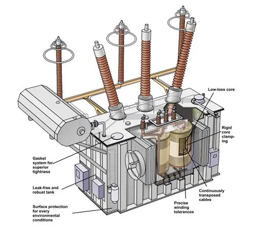
Forståelse how electrical transformers work requires appreciating the clever engineering that makes them so efficient and reliable. Every aspect of transformer construction is optimized to maximize energy transfer while minimizing losses.
The Iron Core: Magnetic Superhighway
The transformer core is the critical component that makes efficient energy transfer possible. Here’s why design matters:
Why Iron? Iron is ferromagnetic, meaning it can concentrate magnetic fields thousands of times better than air. This high magnetic permeability creates a low-resistance path for magnetic flux, dramatically improving transformer efficiency.
Laminated vs. Solid Core: Early transformers used solid iron cores, but engineers quickly discovered a major problem: eddy currents. When solid conductors are exposed to changing magnetic fields, circular currents form within the material, generating heat and wasting energy.
The solution? Laminated cores made from thin sheets (0.25-0.5mm thick) of silicon steel, each insulated from its neighbors by a thin oxide coating or varnish. These laminations:
- Dramatically reduce eddy current formation
- Minimize core heating and energy loss
- Improve overall transformer efficiency to 95-99%
- Allow for better heat dissipation
Silicon Steel: Modern transformer cores use silicon steel rather than pure iron. The silicon increases electrical resistivity, further reducing eddy currents while maintaining excellent magnetic properties.
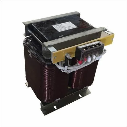
Winding Techniques and Materials
Copper Wire Advantages: Transformer windings use copper wire because copper offers the best combination of electrical conductivity, thermal properties, and cost. Some large transformers use aluminum wire for cost savings, but copper remains the premium choice.
Insulation Importance: Each layer of windings must be perfectly insulated to prevent short circuits. Modern transformers use sophisticated insulation systems including:
- Enamel coating on individual wires
- Paper or polymer insulation between layers
- Oil or gas insulation in large power transformers
Heat Management: Transformers generate heat during operation, primarily from resistance in the windings and magnetic losses in the core. Effective cooling systems—from simple air circulation to complex oil cooling systems—are essential for reliable operation.
Core Types and Shapes
E-I Laminations: The most common transformer construction uses E-shaped and I-shaped laminations stacked alternately. The E pieces form the main body, while the I pieces close the magnetic circuit. This design provides excellent magnetic coupling while allowing easy assembly.
Toroidal Cores: Ring-shaped (toroidal) cores offer several advantages:
- Minimal magnetic flux leakage
- Compact, efficient design
- Quiet operation
- Lower electromagnetic interference
Shell vs. Core Type:
- Core type: Windings wrapped around the core legs (most common for distribution transformers)
- Shell type: Core surrounds the windings (preferred for high-power applications)
Each design has specific advantages depending on the application, voltage level, and power requirements.
Types of Transformers and Their Applications
The principle of how electrical transformers work applies to many different transformer types, each optimized for specific applications.
Krafttransformatorer
Power transformers handle the bulk electrical energy transfer in the power grid:
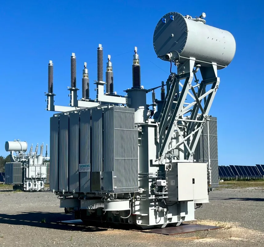
Transmission Transformers: Step up power plant output to high transmission voltages (115kV to 765kV) for efficient long-distance transport. These massive units can weigh hundreds of tons and handle hundreds of megawatts.
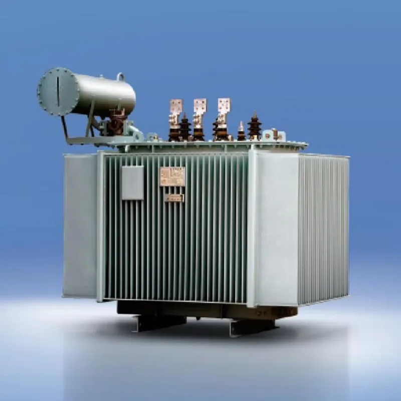
Distribution Transformers: The familiar cylindrical or pad-mounted transformers that step down voltage for neighborhoods and buildings. These workhorses of the electrical grid convert medium-voltage distribution lines (typically 4kV-35kV) to usable voltages (120V-480V).
Substation Transformers: Large transformers that interface between transmission and distribution systems, often stepping down from transmission voltage levels to distribution levels.
Isolasjonstransformatorer
Isolation transformers provide electrical safety by eliminating direct connection between input and output circuits, even when voltage levels remain the same:
Medisinsk utstyr: Hospitals use isolation transformers to protect patients from electrical shock, especially in areas where medical devices contact patients directly.
Sensitive Electronics: Laboratory and testing equipment often requires isolation transformers to eliminate ground loops and electrical noise from the power source.
Sikkerhetsapplikasjoner: Industrial environments use isolation transformers to protect workers and equipment from dangerous ground faults.
Instrument Transformers
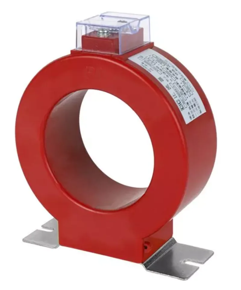
Current Transformers (CTs): Step down high currents to safe, measurable levels for protective relays and metering equipment. These allow power grid monitoring without directly handling dangerous high currents.
Voltage Transformers (VTs): Step down high voltages to safe levels for measurement and protection systems. Essential for monitoring power grid conditions.
Combined Instrument Transformers: Some applications use transformers that provide both current and voltage transformation in a single unit.
Specialty Transformers
Audio Transformers: Optimized for audio frequency response, these transformers provide impedance matching and isolation in high-quality audio equipment.
Pulse Transformers: Designed to handle rapid voltage changes, these are essential in digital electronics and switching power supplies.
Auto-transformers: Single-winding transformers that are more compact and efficient than two-winding types, commonly used in voltage regulators and variable voltage supplies.
Common Transformer Problems and Solutions
Forståelse how electrical transformers work also means recognizing when they’re not working properly. Here are the most common issues:
Overopphetingsproblemer
Symptomer: Hot transformer surfaces, burning smells, oil leaks in large transformers
Årsaker: Overloading, poor ventilation, insulation breakdown, excessive ambient temperature
Løsninger: Load reduction, improved cooling, professional inspection and maintenance
Core Saturation
Symptomer: Excessive heating, distorted output waveforms, loud humming or buzzing
Årsaker: Overvoltage conditions, DC component in AC supply, improper transformer sizing
Løsninger: Voltage regulation, DC blocking, properly sized transformer selection
Insulation Breakdown
Symptomer: Electrical arcing, ground faults, reduced insulation resistance
Årsaker: Age, moisture ingress, thermal stress, electrical overstress
Løsninger: Professional testing, moisture removal, insulation replacement or transformer replacement
Tips om vedlikehold
- Visuell inspeksjon: Regular checks for physical damage, oil leaks, overheating signs
- Electrical testing: Annual insulation resistance and turns ratio testing for critical applications
- Temperaturovervåking: Ensuring proper cooling and ventilation
- Load monitoring: Preventing chronic overloading that shortens transformer life

Real-World Applications You Use Every Day
The principle of how electrical transformers work touches virtually every aspect of modern life:
Phone and Laptop Chargers: These compact switching power supplies use high-frequency transformers to efficiently convert AC wall power to the DC voltages your devices need. The higher frequency allows much smaller, lighter transformers than traditional 60Hz designs.
Microwave Ovens: Use high-voltage transformers to convert household 120V to the 2,000-4,000V needed by the magnetron that generates microwaves. These transformers are specifically designed to handle the high-voltage, high-current demands of microwave generation.
Car Ignition Systems: Modern vehicles use ignition transformers (ignition coils) to convert the car’s 12V battery power to the 10,000-50,000V needed to create spark plugs’ electrical arcs.
Power Grid Infrastructure: Every time you flip a light switch, your electricity has likely passed through 4-6 different transformers:
- Step-up transformer at the power plant
- Transmission substation transformers
- Distribution substation transformers
- Neighborhood distribution transformer
- Possibly building-specific transformers for large facilities
Audio Equipment: High-end audio systems use transformers for impedance matching, noise isolation, and signal coupling. These audio transformers are specially designed to preserve sound quality across the entire audible frequency range.
Sveiseutstyr: Arc welders use transformers to convert standard electrical supply to the high-current, controlled-voltage output needed for welding. These robust transformers must handle extreme electrical and thermal stress.
Energy Efficiency and Losses in Transformers
Moderne electrical transformers work with remarkable efficiency—typically 95-99%—but understanding the small losses helps appreciate their sophisticated design.
Types of Transformer Losses
Copper Losses (I²R Losses): Heat generated by electrical resistance in the windings. These losses increase with current load and can be minimized by using larger conductors and optimal winding design.
Iron Core Losses: Energy lost in the magnetic core material, consisting of:
- Hysteresis losses: Energy required to repeatedly magnetize and demagnetize the core
- Eddy current losses: Circular currents induced in the core material (minimized by laminations)
Stray Losses: Energy lost to electromagnetic fields that don’t contribute to power transfer. Careful design minimizes these through proper magnetic shielding and winding configuration.
Efficiency Improvements
Modern transformer design incorporates numerous efficiency improvements:
- Amorphous steel cores: Newer magnetic materials with lower core losses
- Optimized winding designs: Computer-designed conductor layouts that minimize resistance and stray losses
- Advanced cooling systems: Better heat removal allows higher power density and efficiency
- Load tap changers: Automatic voltage regulation systems that maintain optimal efficiency across varying load conditions
Energy Conservation Benefits
High-efficiency transformers provide enormous energy savings when deployed across the electrical grid. A 1% efficiency improvement in distribution transformers saves billions of kilowatt-hours annually in a large power grid—enough to power hundreds of thousands of homes.
Advanced Concepts: Beyond the Basics
For those interested in deeper understanding of how electrical transformers work, several advanced concepts expand on the basic principles:
Three-Phase Transformers
Most power grid applications use three-phase electricity for more efficient power transmission. Three-phase transformers either use three separate single-phase transformers or a single three-phase unit with three sets of windings on a common core.
Advantages of Three-Phase Systems:
- More efficient power transmission
- Smoother power delivery
- Better motor performance
- Reduced conductor requirements
Auto-Transformers
Auto-transformers use a single winding that serves as both primary and secondary, with electrical connections at different points along the winding. This design is more compact and efficient than separate-winding transformers but provides no electrical isolation.
Bruksområder: Voltage regulators, motor starters, three-phase to two-phase conversion
Variable Transformers
Variable transformers (like Variac® units) allow continuous voltage adjustment by varying the connection point on the transformer winding. These are essential for testing equipment and applications requiring precise voltage control.
High-Frequency Transformers
Modern electronics increasingly use high-frequency transformers (operating at thousands or millions of Hz rather than 60Hz). Higher frequencies allow much smaller transformer cores and improved efficiency in switching power supplies.
Bruksområder: Computer power supplies, LED drivers, wireless charging systems, power inverters
Ofte stilte spørsmål
Installation and Technical Questions
Q: What does it mean when H and X terminals are marked on transformers?
A: H terminals signify high voltage connections while X terminals signify lower voltage connections. A common misconception is that H terminals are always primary and X terminals secondary—this is true for step-down transformers, but in step-up transformers the connections should be reversed.
Q: Can a single-phase transformer be converted to three-phase power?
A: No. Phase converters or phase shifting devices such as reactors and capacitors are required to convert single phase power to three phases. You need either three separate single-phase transformers or a purpose-built three-phase transformer.
Q: What causes loud or unusual noises in transformers?
A: Transformer noise is caused by magnetostriction, which causes magnetic sheet steel to extend when magnetized and contract when demagnetized. Extensions and contractions occur erratically across the core sheets during each AC cycle, creating vibration and noise. Excessive noise may indicate loose components, overloading, or core problems requiring professional inspection.
Q: Why can’t transformers above 1kVA be easily back-fed (used in reverse)?
A: Back feeding larger transformers can result in high inrush currents upon transformer energization and nuisance tripping of circuit breakers and fuses. This issue is difficult to predict and costly to fix. It’s better to purchase transformers specifically wound as step-up units for reverse applications.
Transformer Oil and Maintenance
Q: How long do transformers typically last?
A: A general transformer lifespan can range between 20 and 40 years depending on conditions, from the quality of components to maintenance practices. Some transformers have served for decades with no major problems, while others experience premature wear due to environmental factors or poor maintenance.
Q: What are the main factors that shorten transformer life?
A: The three components that determine transformer lifespan are heat, moisture and oxygen. For every 10°C increase in operating temperature, the oxidation byproducts that attack the cellulose paper double. Proper cooling and avoiding overloading are essential for longevity.
Q: How often should transformer oil be tested?
A: SDMyers recommends annual testing of dielectric liquid samples to provide critical data to pinpoint issues, diagnose potential problems, and prevent failures. The standardization of NFPA 70B in 2023 means annual liquid sampling and testing is now a minimum requirement for transformer maintenance. Critical equipment may require more frequent testing.
Q: What environmental conditions should be avoided when collecting oil samples?
A: Cold conditions, or conditions when relative humidity is in excess of 70 percent, should be avoided, as this will increase moisture in the sample. The ideal situation is 95°F (35°C) or higher, zero percent humidity and no wind.
Q: What does transformer oil actually do?
A: Transformer oil serves three key functions: it’s an excellent dielectric medium for insulating components, a good heat transferring agent to dissipate heat from windings to tank walls and radiators, and it’s still the cheapest fluid available for transformer applications.
Safety and Installation Issues
Q: What happens if a transformer secondary isn’t properly grounded?
A: If the secondary of the transformer is not grounded properly, the output voltage will look ok between the phases but it will float and not be referenced to earth ground. This creates safety hazards and measurement issues.
Q: Do all transformers need vibration pads?
A: All transformers vibrate at 120 Hz because of the electromagnetic field in the core. These vibrations and audible noise can transfer through the floor; vibration pads and isolators help minimize this issue in commercial applications.
Q: Can transformers overheat from harmonic distortion?
A: Due to the prevalence of non-linear loads and the harmonics they produce, transformers can overheat if not specified properly. Modern electronic loads create harmonics that can cause additional heating beyond the nameplate rating.
Performance and Efficiency
Q: What is voltage regulation in transformers?
A: Voltage regulation in transformers is the difference between the full load voltage and the no load voltage, usually expressed in terms of percentage. Good regulation means the output voltage remains stable under varying load conditions.
Q: What is temperature rise in transformers?
A: Temperature rise in a transformer is the average temperature of the windings and oil & insulation above the existing ambient temperature. This specification indicates how much heat the transformer generates during normal operation.
Q: How much can proper maintenance reduce transformer failure rates?
A: Proper maintenance can reduce failure rates by over 40%, extend equipment lifespan, and prevent catastrophic breakdowns. Regular maintenance provides enormous cost savings compared to emergency repairs or replacements.
Troubleshooting and Diagnostics
Q: What should you check first when a transformer isn’t working?
A: If the transformer can be energized, measure output voltage with no load on transformer to ensure voltage is within tolerance. If a neutral is derived on the load side, ensure that neutral ground bonding is accomplished according to National Electric Code requirements.
Q: What are the warning signs of transformer problems?
A: Strange or loud noises are typically caused by vibrations where components are rattling more than usual, indicating loose screws or perhaps even a lack of oil. Smoke is usually caused by exposed wires, which create sparks forming smoke.
Q: What does dissolved gas analysis (DGA) tell you about transformer health?
A: DGA testing identifies dissolved gases in oil such as acetylene, methane, hydrogen, ethane, ethylene, oxygen and carbon monoxide. Different gas combinations indicate specific types of internal problems, allowing predictive maintenance before failures occur.
Q: How often should you perform visual inspections?
A: Monthly visual inspections, semi-annual oil analysis, annual electrical testing, and continuous monitoring of cooling systems form the backbone of effective transformer maintenance programs.
Praktiske anvendelser
Q: Why do power companies use such high transmission voltages?
A: Higher transmission voltages dramatically reduce current for the same power level, which minimizes I²R losses in the transmission lines. This makes long-distance power transmission economical and efficient, but requires transformers to step the voltage back down for safe use.
Q: Can transformers be installed indoors without special considerations?
A: Indoor transformers need adequate ventilation for cooling, proper electrical clearances, and may require special enclosures (NEMA ratings) depending on the environment. Oil-filled transformers may need additional fire protection systems and containment for environmental protection.
Q: What size transformer do I need for my application?
A: Transformer sizing depends on the total connected load, power factor, starting currents of motors, and potential future expansion. A general rule is to size the transformer at 125% of the calculated load, but consult with electrical professionals for specific applications to ensure proper sizing and code compliance.
Konklusjon
Forståelse how electrical transformers work reveals one of humanity’s most elegant engineering solutions. Through the simple yet profound principle of electromagnetic induction, transformers enable our entire electrical infrastructure—from massive power plants to the smartphone charger beside your bed.
The next time you plug in a device or flip a light switch, you’ll appreciate the invisible chain of transformers that make modern electrical power possible. From Michael Faraday’s 1831 discovery to today’s ultra-efficient designs, transformers continue to be the silent heroes that power our world.
Whether you’re a student, professional, or curious learner, grasping these fundamental concepts opens the door to understanding countless other electrical and electronic systems. The principle of electromagnetic induction that powers transformers also drives generators, motors, wireless chargers, and countless other technologies that shape our daily lives.
Ready to explore more electrical engineering concepts? Understanding transformers provides an excellent foundation for learning about power systems, electrical machines, and the fascinating world of electromagnetism that surrounds us every day.
