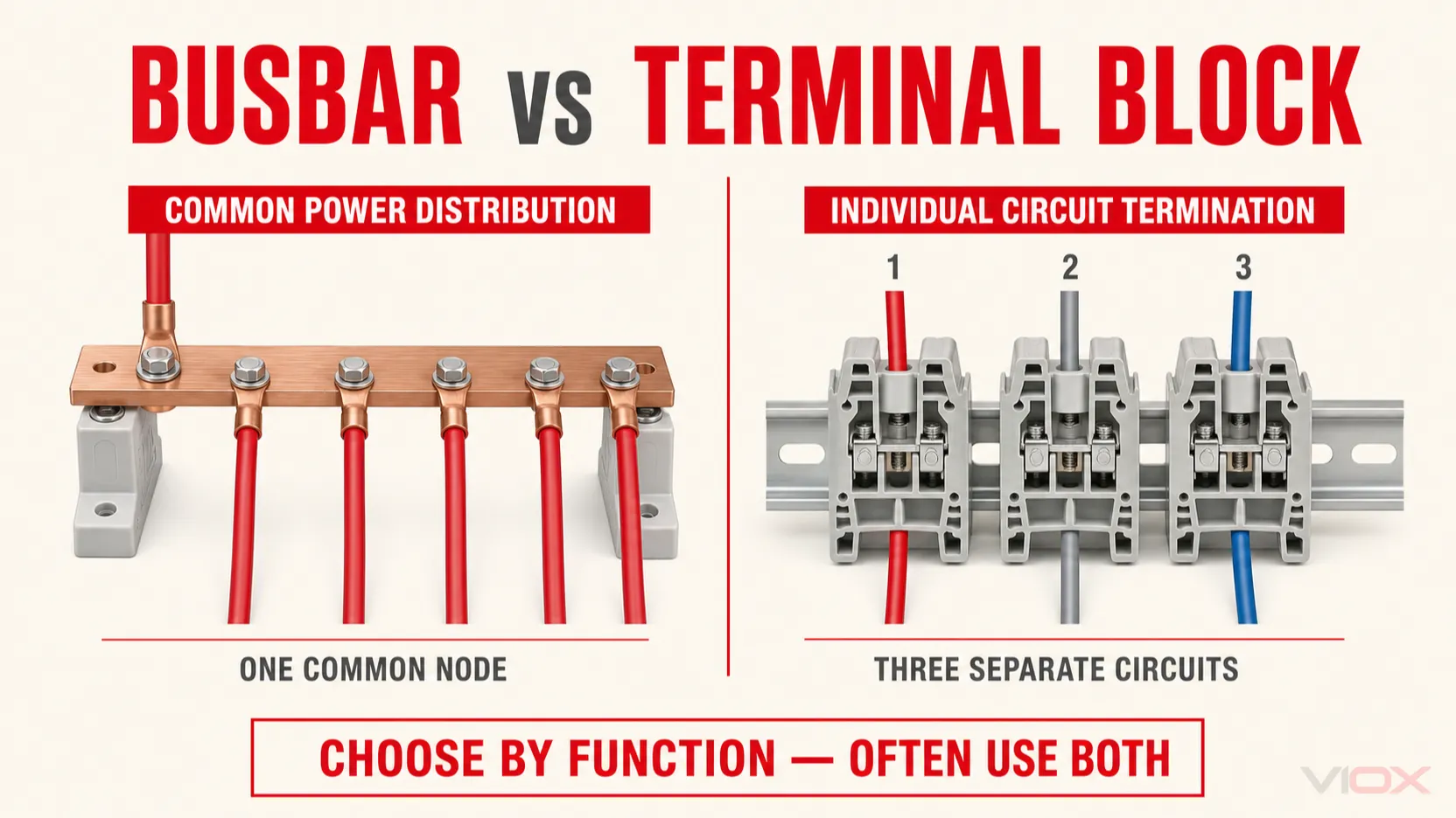
A busbar is normally the better choice when one electrical potential must be distributed to several circuits through a low-impedance common conductor. A terminal block is usually better when the priority is organized wire termination, circuit separation, identification, testing, and field maintenance.
In a real control panel, the decision is rarely busbar or terminal block. Many designs use both: the busbar or a power distribution block handles common power distribution, while terminal blocks organize the individual power, control, signal, and field connections.
Busbar vs Terminal Block at a Glance
| Selection factor | Busbar | Terminal block |
|---|---|---|
| Primary function | Collects or distributes a common electrical potential | Connects and organizes individual conductors or circuits |
| Electrical structure | One continuous conductor or intentionally interconnected conductor system | Separate terminal positions unless connected by approved jumpers |
| Typical role | Common power, neutral, protective earth, battery, or breaker-row distribution | Point-to-point wiring, field termination, marshalling, testing, disconnecting, or fused connections |
| Branching | Efficient when many circuits share one source or potential | Best for circuit-by-circuit connections; jumpers can create limited common distribution |
| Current capability | Often selected for concentrated or higher-current distribution | Depends entirely on the terminal design, conductor range, rating, and installation |
| Circuit separation | Requires separate bars, phases, poles, insulation, or covers | Each terminal position is normally insulated from adjacent positions |
| Identification | Usually identifies the bar or phase group | Supports detailed terminal numbering and conductor identification |
| Testing and isolation | Depends on the busbar system and connected devices | Disconnect, test, and fuse terminal variants simplify circuit-level service |
| Panel layout | Can reduce repeated feeder wiring and centralize distribution | Modular on DIN rail but requires one position per circuit or conductor pair |
| Modification | Tap points and compatibility must be planned | Circuits can often be added, removed, or rearranged more easily |
| Common applications | Switchboards, distribution boards, breaker rows, PE/N bars, battery systems | Control panels, PLC I/O, sensors, actuators, motors, field wiring |
Do not select either component from a generic “high current vs low current” rule. Some terminal blocks accept large conductors, while some PCB or miniature busbars carry relatively modest current. The exact product rating, conductor type, terminal temperature, short-circuit conditions, enclosure design, and applicable assembly standard control the final decision.
What Is a Busbar?
A busbar, also written bus bar, is a common conductive element that collects or distributes electrical power. It is usually made from copper or aluminum and may be formed as a flat bar, strip, comb, rail, laminated conductor, or part of a modular busbar system.
The defining characteristic is not its physical shape or current rating. It is the common electrical node: connection points attached to the same busbar are intentionally at the same electrical potential unless switching or protective devices divide the system.
Common low-voltage examples include:
- main copper bars inside switchboards and distribution assemblies;
- pin or fork comb busbars feeding a row of compatible circuit breakers;
- neutral bars and protective-earth bars;
- DC positive and negative bars in battery, solar, telecom, or control systems;
- modular busbar systems with adapters for breakers, disconnectors, or motor-control components.
A busbar does not automatically provide overcurrent protection or isolation. Those functions must come from the complete system design, such as fuses, circuit breakers, disconnectors, insulated covers, barriers, and enclosure construction.
For modular breaker applications, see the VIOX guide to circuit breaker busbars and the available MCB busbar range.
What Is a Terminal Block?
A terminal block is an insulated connection component that provides a controlled mechanical and electrical interface between conductors. Most industrial terminal blocks are mounted on DIN rail or directly to a panel. Depending on the design, conductors are secured by screw clamp, spring cage, push-in clamp, stud, bolt, or another approved connection method.
A standard feed-through terminal block normally connects the conductors installed on its two sides. Adjacent terminal positions remain electrically separate unless an approved jumper or bridge connects them. This separation makes terminal blocks useful for circuit organization, labeling, testing, and maintenance.
Terminal block functions include:
- feed-through wire-to-wire connection;
- protective-earth connection;
- neutral distribution;
- disconnect or test points;
- fuse integration;
- sensor and actuator marshalling;
- multi-level space-saving connections;
- high-density PLC and control wiring.
Terminal blocks are not limited to low-current signals. The correct distinction is functional: they provide defined conductor termination and circuit organization. Their allowable current and voltage come from the specific product, conductor size and type, connection method, installation, and certification.
For a detailed specification workflow, use the VIOX terminal block selection guide or browse the terminal block product range.
The Core Difference: Common Distribution vs Individual Termination
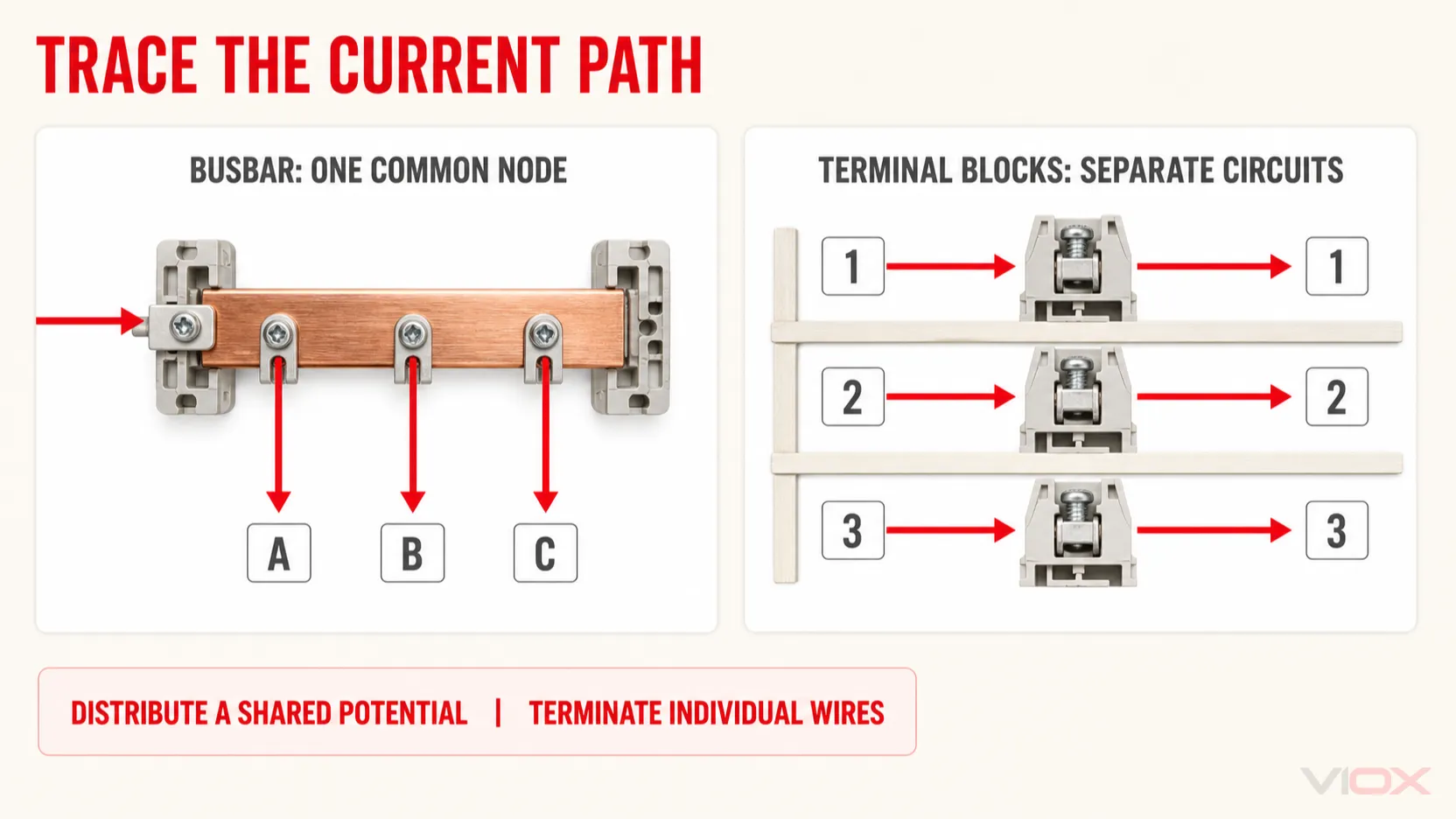
The simplest way to distinguish a busbar from a terminal block is to trace the current path.
With a busbar:
One common conductor → several connected devices or branch points
With separate feed-through terminal blocks:
Circuit 1 input → Circuit 1 output
Circuit 2 input → Circuit 2 output
Circuit 3 input → Circuit 3 output
The busbar intentionally combines connection points into one electrical node. The terminal strip intentionally keeps positions organized and separate. Approved jumpers can connect selected terminal blocks into a common potential group, but that does not make every terminal strip equivalent to a purpose-designed power busbar.
This distinction explains most of their practical differences in branching, labeling, maintenance, and panel architecture.
Choose a Busbar When…
One Source Must Feed Several Circuits
A busbar is effective when several devices require the same phase, DC polarity, neutral, or protective-earth reference. Instead of routing a separate feeder jumper to every device, the common conductor creates a defined distribution path.
Typical examples include a row of compatible miniature circuit breakers, multiple battery branches, a neutral termination section, or a protective bonding system.
Repeated Feeder Wiring Would Consume Too Much Space
A correctly engineered busbar can reduce wire duct, jumper length, and the number of repeated line-side conductors. This can make the panel layout more compact and repeatable, particularly when multiple devices share the same supply arrangement.
However, compactness depends on the system. Required supports, clearances, covers, adapters, bend space, and access for tightening or inspection still occupy panel volume.
A Low-Impedance Common Path Is Required
A properly sized busbar can provide a short, rigid current path with fewer wire-to-wire transitions than a chain of individual jumpers. The design must still be verified for temperature rise, short-circuit forces, conductor material, joint resistance, support spacing, and enclosure conditions.
The Layout Is Stable and Repeatable
Busbars work well where pole sequence, device pitch, tap locations, and future expansion are known. A comb busbar, for example, must match the breaker terminal design, pin or fork geometry, pitch, phase arrangement, rated duty, cutting method, and end-cap system. Similar appearance does not guarantee compatibility.
Choose Terminal Blocks When…
Wires Need Clear Point-to-Point Termination
Terminal blocks create a defined boundary between internal panel wiring and external field wiring. Each conductor can be assigned a terminal number that corresponds to the schematic, wire marker, and commissioning documentation.
This is particularly useful for PLC inputs and outputs, sensors, solenoid valves, contactor coils, motor control circuits, alarms, and instrumentation.
Circuits Must Be Tested or Disconnected Individually
Disconnect and test terminal blocks allow technicians to open or measure a circuit without removing multiple conductors. Fuse terminal blocks add circuit-level fuse accommodation where the product and design require it.
These functions are difficult to reproduce with a simple common busbar because the purpose of a busbar is to maintain a shared electrical node, not isolate each branch for test.
Field Changes Are Expected
DIN-rail terminal systems are modular. Designers can reserve spare positions, add markers, change approved jumpers, or replace individual function terminals without reworking an entire power-distribution structure.
This does not mean every modification is unrestricted. Conductor range, jumper capacity, end plates, separation requirements, and product-family compatibility still need to be checked.
Circuit Identification and Troubleshooting Matter
A technician can follow numbered terminal positions from the drawing to the physical panel. This reduces ambiguity during commissioning, maintenance, and fault finding. For complex control wiring, this serviceability is often more valuable than minimizing every centimeter of DIN-rail space.
Use Both in the Same Panel When…
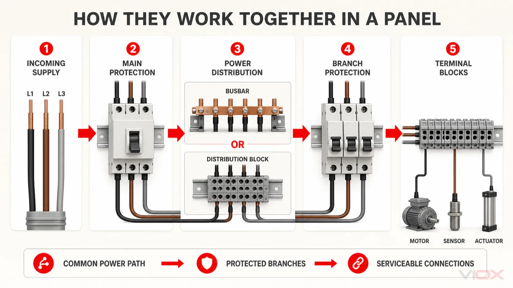
Using both is often the most technically coherent solution because power distribution and circuit termination occur at different layers.
A typical architecture is:
Incoming supply
      ↓
Main protective or switching device
      ↓
Busbar or power distribution block
      ↓
Branch protective devices and power components
      ↓
Terminal blocks
      ↓
Field loads, sensors, actuators, and external wiring
The busbar concentrates the common power path. The terminal blocks provide the serviceable interface to individual circuits. Neither component is being forced to perform the other's main function.
Example: Industrial Control Panel
The incoming three-phase supply feeds a main disconnect and a busbar or distribution block. Branch breakers protect motor starters, power supplies, and auxiliary circuits. DIN-rail terminal blocks then connect motors, push buttons, limit switches, sensors, and field devices.
Example: Distribution Board
A comb busbar supplies a row of compatible miniature circuit breakers. Separate neutral and protective-earth bars collect the corresponding conductors. Terminal blocks may be added for control, metering, alarm, or external-interface wiring.
Example: PLC Cabinet
A compact DC distribution element supplies multiple protected 24 VDC branches. Feed-through, disconnect, and multi-level terminal blocks marshal the individual PLC I/O and field conductors. The common supply and individual signals remain physically and logically organized.
Busbar vs Power Distribution Block vs Terminal Block
These three components overlap, but they are not identical.
| Component | Main function | Typical construction | Best use |
|---|---|---|---|
| Busbar | Creates a common current-carrying node | Bar, strip, comb, rail, or modular conductor system | Repeated common distribution across devices or circuits |
| Power distribution block | Splits one or more incoming conductors into defined outgoing terminals | Conductive body inside an insulated housing | Feeder-to-branch power splitting with specified input/output conductor ranges |
| Terminal block | Terminates and organizes individual conductors | Insulated modular positions with clamping units | Point-to-point wiring, marshalling, testing, disconnecting, and circuit identification |
A power distribution block is often the middle option. Internally, it uses a common conductive element like a busbar, but it is supplied as a packaged component with defined input and output terminals, insulation, mounting, and published conductor ranges.
Use a power distribution block when one large incoming conductor must feed several outgoing conductors and a packaged, finger-protected connection arrangement fits the panel better than an exposed or modular busbar system. Use terminal blocks when circuits must remain individually organized. Use a busbar when distribution directly across compatible devices or a purpose-designed common conductor system provides the cleaner architecture.
Read the VIOX guide to power distribution blocks or compare the VIOX power distribution block range for that adjacent selection decision.
Six Practical Application Scenarios
1. Multiple Circuit Breakers Sharing One Incoming Supply
Use a compatible comb busbar when the breaker series, pitch, pole sequence, terminal design, and published ratings permit it. Do not assume that a busbar fitting physically means the device combination is approved.
2. Neutral and Protective-Earth Connections
Dedicated neutral and PE bars provide common termination points, but their bonding and isolation depend on the earthing system and panel position. Neutral and protective-earth conductors must not be combined merely because both use bar-shaped components.
3. PLC and Sensor Field Wiring
Use terminal blocks. Circuit numbering, multi-level arrangements, shielding accessories, disconnect points, and easy replacement generally matter more than creating one common current node.
4. Main Feed Split into Several Branch Conductors
Evaluate a power distribution block or engineered busbar system. Avoid placing several conductors under one device terminal unless the terminal is specifically rated for that number, material, and size of conductors.
5. Circuits Requiring Frequent Measurement or Isolation
Use disconnect or test terminal blocks where the product is suitable. They allow a branch to be opened or measured without dismantling the common distribution path.
6. Panel with High-Power and Control Sections
Use a busbar or power distribution block in the power section and terminal blocks in the control and field-wiring section. Maintain the required segregation, creepage, clearance, wiring routes, and access for maintenance.
Selection Checklist
Before choosing a busbar, terminal block, or distribution block, verify the following.
Electrical Function
- Is the connection a common potential or an individual point-to-point circuit?
- Is the component distributing power, terminating wires, providing PE continuity, or enabling test and disconnect functions?
- Is overcurrent protection required upstream or on each branch?
Ratings and Fault Conditions
- rated operational voltage and current;
- AC or DC suitability and polarity where applicable;
- short-time or short-circuit withstand information;
- upstream protective-device coordination;
- allowable temperature rise under the assembly's operating conditions.
Conductors and Connections
- copper, aluminum, or mixed-metal connection suitability;
- conductor cross-section in mm² or AWG;
- solid, stranded, compacted, or fine-stranded conductor class;
- number of conductors permitted per connection;
- ferrule, cable lug, preparation, strip length, and tightening requirements.
Mechanical Integration
- DIN rail, panel, support, or direct-device mounting;
- busbar supports and spacing;
- pin, fork, stud, bolt, or clamp geometry;
- breaker pitch and phase sequence;
- wiring bend space and maintenance access;
- covers, end plates, barriers, and touch protection.
Maintenance and Expansion
- terminal numbering and conductor identification;
- need for test points or circuit isolation;
- spare terminal positions or future tap points;
- inspection and retightening requirements;
- availability of compatible replacement parts.
Compliance
For IEC-oriented industrial terminal blocks, IEC 60947-7-1:2025 specifies requirements for terminal blocks and test-disconnect terminal blocks for copper conductors within its scope. Low-voltage switchgear and controlgear assemblies are addressed by the relevant parts of the IEC 61439 series; IEC 61439-1:2020 provides general rules but is not used alone to claim conformity for an assembly.
For North American projects, terminal blocks are commonly evaluated to UL 1059 or relevant ANSI/UL 60947-7 requirements. UL Solutions identifies these pathways for terminal-block certification. Power distribution blocks may follow a different product and panel-application path, so verify the component's certification, conditions of acceptability, and the applicable panel standard rather than relying on appearance or product name.
Common Design Mistakes
Selecting Only by Current Rating
Current is essential, but it is not the complete selection basis. A component may meet the nominal current and still be unsuitable because of conductor class, terminal temperature, voltage, short-circuit conditions, spacing, or certification.
Using a Terminal Strip as an Unverified Feeder Bus
Jumpers can distribute a common potential across terminal blocks, but the current through the jumper path and each terminal position must remain within the manufacturer's published arrangement. Do not assume that adding more jumpers creates the equivalent of a purpose-designed feeder busbar.
Treating a Busbar as Circuit Protection
A busbar distributes current; it does not automatically interrupt overload or short-circuit current. Each branch needs the protection required by the circuit and applicable rules.
Confusing DIN Rail with a Busbar
A standard DIN rail mechanically supports components. It is not normally a line-power conductor. Certain PE terminal blocks intentionally connect protective conductors to a grounded rail, but that specific function does not turn every DIN rail into a general power busbar.
Mixing Neutral and Protective Earth
Neutral and PE bars may look similar, but their bonding and isolation requirements differ. Follow the applicable earthing arrangement and distribution-board location.
Ignoring Terminal and Busbar Compatibility
Matching nominal pitch or conductor size is insufficient. Verify terminal geometry, insertion depth, contact pressure, pole sequence, insulation accessories, tightening instructions, and device approval.
Overlooking Heat and Joint Quality
Temperature rise often begins at a connection rather than in the bulk conductor. Incorrect torque, poor crimping, oxidation, incompatible materials, conductor damage, or inadequate contact pressure can create local resistance and overheating.
Final Recommendation
Choose a busbar when the design needs a planned common electrical node that distributes power efficiently across several compatible circuits or devices. Choose terminal blocks when the design needs individual conductor termination, circuit separation, labeling, testing, or field-service access.
Choose a power distribution block when one feeder must be divided into several defined outgoing conductors through a packaged connection component.
For many low-voltage panels, the best architecture uses all three at different layers: busbars for common distribution, distribution blocks for feeder splitting, and terminal blocks for circuit-by-circuit connections. Start with the required electrical function, then verify the exact product ratings, conductor compatibility, fault conditions, assembly design, and applicable standards.
VIOX supplies MCB busbars, terminal blocks, and power distribution blocks for low-voltage distribution and control-panel applications. Select from published model data or contact VIOX with the circuit function, voltage, load current, conductor sizes, branch count, mounting method, and destination-market requirements.
FAQ
Is a busbar the same as a terminal block?
No. A busbar intentionally forms a common electrical node for power distribution. A terminal block provides defined conductor terminations, with adjacent positions normally separated unless connected by approved jumpers.
Which is better, a busbar or terminal block?
Neither is universally better. Use a busbar for common distribution and a terminal block for individual circuit termination, organization, testing, and maintenance. Many panels require both.
Can terminal blocks distribute power?
Yes, if the terminal blocks and approved jumper system are rated for the circuit and arrangement. For larger feeder-to-branch splitting, a purpose-designed power distribution block or busbar system may be more appropriate.
Can a busbar replace terminal blocks?
Not when the design needs individually numbered, isolated, disconnectable, fused, or testable wire terminations. A busbar and terminal strip perform different primary functions.
What is a terminal bus bar?
The term usually describes a common conductive bar fitted with several connection points or terminals. Because suppliers use the term differently, verify whether the product is a bare busbar, neutral or earth bar, packaged distribution block, or terminal strip with jumpers.
Is a power distribution block a terminal block?
They are related but not necessarily interchangeable. A power distribution block is designed specifically to split an incoming power feed into multiple outputs. A standard terminal block primarily connects and organizes individual conductors.
Are busbars always rated for more current than terminal blocks?
No universal statement is valid. Ratings vary widely with construction and application. Compare the exact products under the actual conductor, temperature, enclosure, and fault conditions.
Does a busbar provide circuit protection?
No, not by itself. A busbar is a conductor. Overcurrent and short-circuit protection must be provided by appropriate protective devices in the complete system.
Can a DIN rail carry current?
A standard DIN rail is primarily a mechanical mounting support. PE terminal systems may intentionally use a grounded rail for protective-conductor continuity, but the rail should not be treated as a general line or neutral busbar unless the system is specifically designed and approved for that function.